Table of Contents
Advertisement
Quick Links
Advertisement
Table of Contents

Related Manuals for Interlogix MC352-1P/1S


Summary of Contents for Interlogix MC352-1P/1S
- Page 1 IFS MC352-1P/1S User Manual P/N 1072579 • REV 00.005 • ISS 30JAN13...
- Page 2 Copyright © 2013 UTC Fire & Security Americas Corporation, Inc. Interlogix is part of UTC Climate Controls & Security, a unit of United Technologies Corporation. All rights reserved. The IFS MC352-1P/1S and logo are trademarks of United Trademarks and patents Technologies.
-
Page 3: Table Of Contents
Link Fault Pass through (LFP) 12 Link Loss Carry Forward (LLCF) 12 Link Loss Return (LLR) 13 Stand-alone Installation 15 802.3at/802.3af Installation 16 LED indicators 17 Cable Connection 20 Specifications 21 RJ45 Pin Assignments 23 Contacting Technical Support 25 IFS MC352-1P/1S User Manual... -
Page 5: Overview
Overview The MC352-1P/1S Industrial 802.3at High Power over Ethernet Gigabit Media converter fully complies with IEEE 802.3 10Base-T, IEEE 802.3u, 100Base-TX, IEEE 802.3ab 1000Base-T and IEEE 802.3z 1000Base-SX / LX standards. The Gigabit media conversion is quick and easy by simple plug and play installation. -
Page 6: Product Description
Being able to operate under the temperature range from -40 to 75 Degree C allows the MC352-1P/1S to be used in almost any demanding environment. The maximum distance between the PoE PSE to PD is 100 meters. - Page 7 • 1000Mbps support on the fiber optic port The MC352-1P/1S is a Single-Port, End-Span Industrial IEEE 802.3at High Power over Ethernet Gigabit Media converter with maximum power output of up to 30 Watts over Ethernet cables. It is designed specifically to meet the power requirements of network equipment such as PTZ (Pan, Tilt &...
-
Page 8: Hardware Overview
Hardware Overview Figure 1: All Panel Views IFS MC352-1P/1S User Manual... -
Page 9: Front Panel
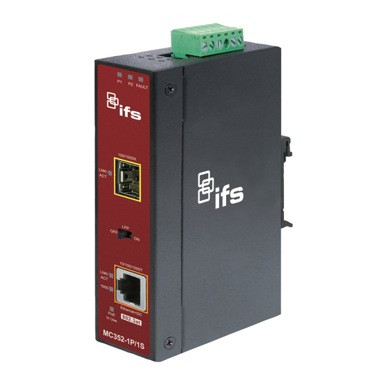
Front Panel The Front Panel of the Industrial 802.3at PoE Media Converter consists of one 1000Base-SX / 1000Base-LX / mini-GBIC SFP port and one Auto-Sensing 10/100/1000Mbps Ethernet RJ-45 Port. IFS MC352-1P/1S User Manual... -
Page 10: Top Panel
Top Panel The top panel of the MC352-1P/1S Media Converter consists of one terminal block connector within two DC power inputs. Wiring the Power Inputs The 6-contact terminal block connector on the top panel of the MC352-1P/1S is used for two DC redundant power inputs. -
Page 11: Wiring The Fault Alarm Contact
The fault alarm contacts are in the middle of the terminal block connector as the picture shows below. Inserting the wires, the MC352-1P/1S will detect the fault status of the power failure and then forms an open circuit. The following illustration shows an application example for wiring the fault alarm contacts. -
Page 12: Mounting Installation
GE-DSGH-8 as an example. However, the steps for any IFS Industrial Switch & Industrial Media Converter are similar. Mounting to a DIN-Rail The DIN-Rail kit comes assembled on the MC352-1P/1S out of the box. Please refer to following figures to mount the MC352- 1P/1S on a DIN-Rail. - Page 13 1. Lightly press down and push the bottom of the DIN-Rail connector mount into the track. 2. Check that the DIN-Rail connector mount is tightly mounted on the track. 3. Please refer to following procedures to remove the MC352- 1P/1S from the track. IFS MC352-1P/1S User Manual...
- Page 14 4. Lightly press down and pull the bottom of the DIN-Rail connector mount to remove it from the track. Mounting to a Wall To install the MC352-1P/1S on the wall, please follow the instructions described below. 1. Loosen the screws to remove the DIN Rail from the Media Converter.
- Page 15 2. Place the wall mount plate on the rear panel of the MC352- 1P/1S. 3. Assemble the wall mount plate on the MC352-1P/1S. 4. Use the hook holes at the corners of the wall mount plate to mount the MC352-1P/1S on the wall.
-
Page 16: Link Fault Pass Through (Lfp)
The diagram below shows a typical network configuration with a good link status using MC352-1P/1S for remote connectivity. In case of a connectivity issue, the MC352-1P/1S media converter LLCF sends the notification to the switch/hub that generates a trap to the management station. -
Page 17: Link Loss Return (Llr)
* The factory default setting for the LFP function is "off". Link Loss Return (LLR) The fiber ports of the MC352-1P/1S have been designed with an LLR function for troubleshooting a remote connection. LLR works in conjunction with LLCF. When the LFP function is enabled, the port’s transmitter shuts down when its receiver fails to detect a valid connection. - Page 18 (i.e. checking which end is broken in a connection), you can turn the switch to the on position and reset the converter for changes to take effect. Otherwise, it's recommended to keep the DIP switch in its default position. IFS MC352-1P/1S User Manual...
-
Page 19: Stand-Alone Installation
Stand-alone Installation Please follow these steps to install the MC352-1P/1S: The SFP transceivers are hot-swappable, you can insert or remove the transceiver from an SFP port without having to power down the Industrial 802.3at PoE Media Converter. To install the MC352-1P/1S with 100Base-FX, 1000Base-SX / LX SFP, simply complete the following steps: Step 1: Insert in the 100Base-FX, or 1000Base-SX / LX SFP. -
Page 20: 802.3At/802.3Af Installation
802.3at/802.3af Installation Before your installation, it is recommended to check your network environment. The MC352-1P/1S requires 48VDC or 24VDC input and it injects the DC power into the pin of the twisted pair cable (Pin 1, 2, 3 and 6). -
Page 21: Led Indicators
Function Lit: indicates that the Fiber Optical Port is successfully Fiber Green connecting to the network at 100Mbps / 1000Mbps. LNK/ACT Blinks: indicates that the Fiber Optical Port is receiving or sending data. Gigabit TP Interface IFS MC352-1P/1S User Manual... - Page 22 Lit: Indicates that the port is providing DC 52V to remote Orange powered device. Off: Indicates that the port is not providing DC 52V to remote powered device. System Color Function Lit: Indicates that the device is powered. Green IFS MC352-1P/1S User Manual...
- Page 23 TP 1000 Off: Indicates a 10/100 Mbps Full duplex connection. 1000Base-SX/LX SFP Slot Color Function Lit: Indicates a successful link through the fiber port Fiber Green Blinking: Indicates the data activity through the fiber port. LNK/ACT IFS MC352-1P/1S User Manual...
-
Page 24: Cable Connection
62.5 1000Base 62.5 5000* Note: The single mode port (1000Base-LX port) of the MC352-1P/1S, is compliant with LX 5 kilometers and provides additional margin allowing for a 10/30/70 kilometer Gigabit Ethernet links on single mode fiber. IFS MC352-1P/1S User Manual... -
Page 25: Specifications
6KV DC ESD Protection 6KV DC EFT Protection Provides one relay output for power fail Alarm Alarm Relay current carry ability: 1A @ DC 24V Twisted-pair: Speed 10/20Mbps for Half/Full-Duplex,100/200Mbps for Half / Full-Duplex 1000/2000Mbps for Full-Duplex IFS MC352-1P/1S User Manual... - Page 26 IEEE 802.3af Power over Ethernet IEEE 802.3at High Power over Ethernet IEC60068-2-32(Free fall) IEC60068-2-27(Shock) Stability Testing IEC60068-2-6(Vibration) When connecting to other Ethernet equipment such as a Router, Bridge, Switch, or Hub, please refer to that device’s Technical Manual. IFS MC352-1P/1S User Manual...
-
Page 27: Rj45 Pin Assignments
4, 5 Not used Rx - (receive) Tx - (transmit) 7, 8 Not used RJ45 Cable Drawing The following figure shows the pin allocation and color of a straight cable, and connection of a crossover cable. IFS MC352-1P/1S User Manual... - Page 28 Please make sure your connected cables are with same pin assignment and color as above picture before deploying the cables into your network. IFS MC352-1P/1S User Manual...
-
Page 29: Contacting Technical Support
Contact technical support if you encounter any difficulties during this installation. Please make sure you have the requested diagnostic or log files ready before you contact us by phone or go to www.interlogix.com/customer-support. Technical Support Europe, Middle East and Africa Select Contact Us at www.utcfssecurityproducts.eu...