Table of Contents
Advertisement
Quick Links
Advertisement
Table of Contents

Related Manuals for Interlogix IFS MC251-4P/1CXT


Summary of Contents for Interlogix IFS MC251-4P/1CXT
- Page 1 IFS MC251-4P/1CXT User Manual P/N 1072578 • REV 00.05 • ISS 30JAN13...
- Page 2 Copyright © 2013 UTC Fire & Security Americas Corporation, Inc. Interlogix is part of UTC Climate Controls & Security, a unit of United Technologies Corporation. All rights reserved. The IFS MC251-4P/1CXT and logo are trademarks of United Trademarks and Technologies.
-
Page 3: Table Of Contents
Installing the MC251-4P/1CXT 8 MC251-4P/1CXT BNC/RJ-11 Connection 9 MC251-4P/1CXT Application Connection 10 Wiring the Power Inputs 13 Wiring the Fault Alarm Contact 14 Mounting Installation 15 Troubleshooting 19 FAQs 20 Specifications 22 Contacting Technical Support 24 IFS MC251-4P/1CXT User Manual... -
Page 5: Overview
Overview Package Contents Before installing the IFS MC251-4P/1CXT Industrial Ethernet Converter, verify that the package contains the following parts: MC251-4P/1CXT x1 • • DIN Rail Kit x1 • Wall Mount Kit x1 • User’s Manual x1 If any of the items in the package are damaged or missing, please contact your distributor or IFS sales rep. - Page 6 IP30 standards for deployment in demanding industrial environments. The IFS MC251-4P/1CXT provides a lower cost replacement and smooth migration for existing Long Reach Ethernet (LRE) networks. The cable specifications of the connection are listed as following: •...
-
Page 7: Key Features
Integrated address look-up engine, support 2K absolute MAC addresses • VDSL2 Stand-Alone transceiver for simple bridge modem application • Selectable Target Band Plan and Target SNR Margin • LED indicators for network diagnostics • DIN Rail and Wall Mount Design IFS MC251-4P/1CXT User Manual... -
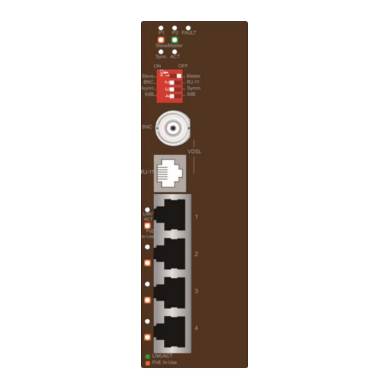
Page 8: Hardware Overview
4P/1CXT , familiarity with its display indicators and ports. Front panel illustrations in this chapter display the unit LED indicators is important. Before connecting any network device to the MC251-4P/1CXT , read this chapter carefully. Figure 1: Front Panel IFS MC251-4P/1CXT User Manual... -
Page 9: Led Indicators
Indicate the port is providing 48V DC in-line power. Orange Light in-Use (Ports 1-4). Mode DIP Switch The MC251-4P/1CXT provides 4 selective transmission modes. By switching the transmission modes, you can obtain a best transmission mode to suit the phone line quality or IFS MC251-4P/1CXT User Manual... - Page 10 PC, VoIP, Wireless Access Point, etc. When the MC251-4P/1CXT is operating in Slave mode, the DIP switch 2, 3, and 4 are disabled. Link Type • BNC mode allows the MC251-4P/1CXT to connect and data transfer by using BNC cable IFS MC251-4P/1CXT User Manual...
-
Page 11: Top Panel
Please power off the MC251-4P/1CXT before making any transmission mode adjustments. Top Panel The top panel of the MC251-4P/1CXT consists of a terminal block connector with two DC power inputs. Figure 2 shows the top panel of the MC251-4P/1CXT. IFS MC251-4P/1CXT User Manual... -
Page 12: Installation
Coaxial: Depending on the quality of the coaxial cable being used, the maximum distance of one VDSL segment is 3.0km (9842ft) with 50 or 75 ohm coaxial cable. The distance achieved will vary according to the quality of telephone wires and coaxial cables. IFS MC251-4P/1CXT User Manual... -
Page 13: Mc251-4P/1Cxt Bnc/Rj-11 Connection
MC251-4P/1CXT BNC/RJ-11 Connection The IFS MC251-4P/1CXT has a DIP switch which can adjust the unit to be in Master or Slave mode. Connection of two IFS MC251-4P/1CXT units, one must be set to Master (CO) mode and the other must be set to Slave (CPE) mode. Please refer to the following figure. -
Page 14: Mc251-4P/1Cxt Application Connection
AP can be easily installed around the corner in the company for surveillance demands or build a wireless roaming environment in the offices. Without an AC power outlet limitation, it makes the installation of cameras or WLAN AP more easily and efficiently. IFS MC251-4P/1CXT User Manual... - Page 15 C which can handle any harsh environment and places. It is also compatible with IFS MCR200-1T/1CX and MC250- 4T/1CXT. Without spending extra cost to deploy a new local Internet in apartment, hotel, campus and hospitality environment. IFS MC251-4P/1CXT User Manual...
- Page 16 (we recommend that it has a minimum of 25mm clearance). To prolong the operational life of your units: • Do not place objects on top of any unit or stack. IFS MC251-4P/1CXT User Manual...
-
Page 17: Wiring The Power Inputs
1. Insert positive / negative DC power wires into the contacts 1 and 2 for POWER 1, or 5 and 6 for POWER 2. V1- V1+ V2- V2+ 2. Tighten the wire-clamp screws to prevent the wires from disconnecting. Power 1 Fault Power 2 IFS MC251-4P/1CXT User Manual... -
Page 18: Wiring The Fault Alarm Contact
Insert the wires into the fault alarm contacts Note: The wire gauge for the terminal block should be in the range between 12 ~ 24 AWG. The alarm relay circuit accepts up to 30V, max. 3A currents. IFS MC251-4P/1CXT User Manual... -
Page 19: Mounting Installation
The DIN-Rail kit comes assembled on the MC251-4P/1CXT out of the box. Please refer to following figures to hang the MC251-4P/1CXT on a DIN-Rail. 1. Lightly press down and push the bottom of the DIN-Rail connector mount into the track. IFS MC251-4P/1CXT User Manual... - Page 20 2. Check that the DIN-Rail connector mount is tightly mounted on the track. 3. Please refer to following procedures to remove the MC251- 4P/1CXT from the track. IFS MC251-4P/1CXT User Manual...
- Page 21 To install the MC251-4P/1CXT on the wall, please follows the instructions described below. 1. Loosen the screws to remove the DIN Rail from the Media Converter. 2. Place the wall mount plate on the rear panel of the MC251- 4P/1CXT. IFS MC251-4P/1CXT User Manual...
- Page 22 3. Assemble the wall mount plate on the MC251-4P/1CXT. 4. Use the hook holes at the corners of the wall mount plate to hang the MC251-4P/1CXT on the wall. IFS MC251-4P/1CXT User Manual...
-
Page 23: Troubleshooting
Make sure that all cables are properly plugged into the • correct ports. Make sure that the cable is not bad. • Make sure that the power adapters are functional for each • device. IFS MC251-4P/1CXT User Manual... -
Page 24: Faqs
200 meters, 99Mbps/63Mbps (downstream/upstream) for telephone cable or 100Mbps/65Mbps (downstream/upstream) for coax cable. Q5: What is SNR and what’s the effect? A5: In analog and digital communications, Signal-to-Noise Ratio, (SNR), is a measure of signal strength relative to IFS MC251-4P/1CXT User Manual... - Page 25 (by designated frequency bands) for the transmission of upstream and downstream signals. User has the ability to select fixed band plan. Symmetric band plan provides better downstream performance while Asymmetric band plan provides better upstream performance. IFS MC251-4P/1CXT User Manual...
-
Page 26: Specifications
100Base-TX: 2-pair UTP Cat.5, 5e, 6 up to 100m (328ft) Twisted-pair telephone wires (AWG24 or better) up to 1.4km Cabling VDSL(RJ-11) 50 ohm: RG58A/U, RG58C/U, RG58/U and 75 ohm: RG6 (Distance 2.4km) Asymmetric Mode VDSL (RJ-11) IFS MC251-4P/1CXT User Manual... - Page 27 *1 BNC and RJ-11 mode must be switched to the same position for Master and Slave. Otherwise, it may cause instability. *2. The actual data rate will vary on the quality of the copper wire and environment factors. IFS MC251-4P/1CXT User Manual...
-
Page 28: Contacting Technical Support
Contact technical support if you encounter any difficulties during this installation. Please make sure you have the requested diagnostic or log files ready before you contact us by phone or go to www.interlogix.com/customer-support. Technical Support Europe, Middle East and Africa Select Contact Us at www.utcfssecurityproducts.eu...