Table of Contents
Advertisement
Quick Links
Advertisement
Table of Contents

Related Manuals for Interlogix IFS MCR200-1T-1TW


Summary of Contents for Interlogix IFS MCR200-1T-1TW
- Page 1 IFS MCR200-1T-1TW User Guide P/N 1072685 • REV A • ISS 30OCT13...
- Page 2 Copyright © 2013 United Technologies Corporation Interlogix is part of UTC Climate Controls & Security, a unit of United Technologies Corporation. All rights reserved. Trademarks and The IFS MCR200-1T-1TW name and logo are patents trademarks of United Technologies. Other trade names used in this document may be...
- Page 3 European Union. For proper recycling, return this product to your local supplier upon the purchase of equivalent new equipment, or dispose of it at designated collection points. For more information see: www.recyclethis.info. Contact For contact information, see www.interlogix.com information or www.utcfssecurityproducts.eu.
-
Page 4: Table Of Contents
Key Features 4 Specifications 5 Hardware Description Front Panel 7 The Rear Panel 9 Installation Install Ethernet over VDSL2 Converter 12 Connecting MCR200-1T-1TW 13 Chassis Installation and Rack Mounting (MCR200-1T-1TW) 15 POWER INFORMATION Troubleshooting Customer Support IFS MCR200-1T-1TW User Guide... -
Page 5: Introduction
Customer Premises Equipment (CPE) mode via a DIP switch. When MCR200-1T-1TW is connected with other MCR200-1T-1TW devices, the performance will up to 100/55Mbps for asymmetric data rate within 200m and up to 25/4Mbps for asymmetric data rate at 1.6km. IFS MCR200-1T-1TW User Guide... - Page 6 (CO) through the telephone wire or coaxial cable. It is not allow connecting like Master to Master or Slave to Slave. To define the MCR200-1T-1TW to CO or CPE, please refer to “MODE DIP Switch” on page 9 for more detail. IFS MCR200-1T-1TW User Guide...
-
Page 7: Key Features
■ Support up to 1536 bytes packet size, 802.1Q VLAN tag transparent ■ VDSL2 Stand-Alone transceiver for simple bridge modem application ■ Selectable Target Band Plan and Target SNR Margin ■ Support extensive LED indicators for network diagnostics IFS MCR200-1T-1TW User Guide... -
Page 8: Specifications
2 for RJ-45 10/100Base-TX port • 10Base-T: 2-pair UTP Cat.3,4,5 up to 100m (328ft) • 100Base-TX: 2-pair UTP Cat.5, 5e, 6 up to 100m Ethernet (328ft) Cabling Twisted-pair telephone wires (AWG24 or better) up VDSL to 1.6km IFS MCR200-1T-1TW User Guide... - Page 9 IEEE 802.3x Full Duplex Pause frame Flow Control Standards ITU-T Compliance 。 G.997.1 。 G.993.1 VDSL 。 G.993.2 VDSL2 (Profile 17a) * The actual data rate will vary on the quality of the copper wire and environment factors. IFS MCR200-1T-1TW User Guide...
-
Page 10: Hardware Description
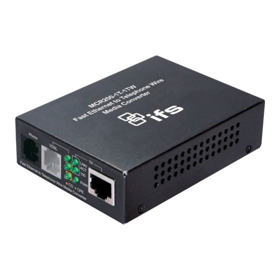
LED indicators. Before connecting any network device to the converter, read this chapter carefully. Front Panel The units’ front panel provides a simple interface monitoring the Ethernet over VDSL2 Converter. ■ MCR200-1T-1TW Front Panel Figure 1: MCR200-1T-1TW front panel IFS MCR200-1T-1TW User Guide... - Page 11 Indicate that the port is operating at Light 100Mbps. Green Indicate that the port is Link Down or 10Mbps. Indicate the VDSL Bridge is running at CO Green Light mode. Indicate the VDSL Bridge is running at CPE Green Light mode. IFS MCR200-1T-1TW User Guide...
-
Page 12: The Rear Panel
The following is the summary table of transmission setting, bandwidth and distance extensibility tested for AWG 24 (0.5mm) twisted- pair without noise and cross talk. IFS MCR200-1T-1TW User Guide... - Page 13 “CPE”. For operate as “CO”, please adjust the DIP 1 switch to “OFF” position. Adjust other DIP switch setting to fill different network application demand. Please power off the Ethernet over VDSL2 Converter before making any transmission mode adjustment. IFS MCR200-1T-1TW User Guide...
- Page 14 In some area, installing a surge suppression device may also help to protect your Ethernet Over VDSL2 Converter from being damaged by unregulated surge or current to the Ethernet over VDSL2 Converter or the power adapter. IFS MCR200-1T-1TW User Guide...
-
Page 15: Installation
Area networks that are located in different place. Through the normal telephone line, it could setup a 100/55Mbps asymmetric backbone, but one Ethernet over VDSL2 Converter must be Master (CO mode) and the other one is Slave (CPE mode). IFS MCR200-1T-1TW User Guide... -
Page 16: Connecting Mcr200-1T-1Tw
The MCR200-1T-1TW. LNK LED will blink to illuminate. Connect telephone to the PHONE port. Connect Ethernet port to PC Network Interface Card (NIC) via regular Cat. 5, 5e or 6 cable. Figure 3-4: Connecting Standalone PC IFS MCR200-1T-1TW User Guide... - Page 17 MCR200-1T-1TW: Connect Ethernet port to Ethernet Switch (or Broadband Router) via regular Cat. 5, 5e or 6 cables. Figure 3-5: Connecting Multiple PCs to an Ethernet LAN Please refer to your Ethernet device User’s Manual for the device’s set up information. IFS MCR200-1T-1TW User Guide...
-
Page 18: Chassis Installation And Rack Mounting (Mcr200-1T-1Tw)
Installation to connect the network cabling and supply power to your Converter Chassis You must use the screws supplied with the mounting brackets. Damage caused to the parts by using incorrect screws would invalidate your warranty. IFS MCR200-1T-1TW User Guide... -
Page 19: Power Information
DC Receptacle 2.5mm +5V for each slot For Media Chassis DC receptacle is 2.5mm wide that conforms to and matches the VDSL2 Converter 2.5mm DC jack's central post. Do not install any improper devices in Media Chassis IFS MCR200-1T-1TW User Guide... -
Page 20: Troubleshooting
Check the converter and the connected device’s power are ON or OFF. Check the port’s cable is firmly seated in its connectors in the switch and in the associated device. Check the connecting cable is good. Check the power adapters are functional, including the connecting device. IFS MCR200-1T-1TW User Guide... -
Page 21: Faq
The greater the ratio, the easier it is to identify and subsequently isolate and eliminate the source of noise. Generally speaking, the higher SNR value gets better line quality, but lower performance. IFS MCR200-1T-1TW User Guide... - Page 22 User has the ability to select fixed band plan. When Symmetric is selected that provides better downstream performance, when Asymmetric is selected that provides better upstream performance. IFS MCR200-1T-1TW User Guide...
-
Page 23: Customer Support
Level 1 271-273 Wellington Road Mulgrave, Victoria 3170 Latin America: Latam@interlogix.com 1-561-998-6114 EMEA: +32 (0)2 725 1120 emea@fs.com EMEA Headquarters UTC Fire & Security EMEA BVBA (Europe, Middle East & Africa) Kouterveldstraat 2 1831 Diegem-Brussels, Belgium IFS MCR200-1T-1TW User Guide...