
Related Manuals for Interlogix IFS MC251-4P/1S


Summary of Contents for Interlogix IFS MC251-4P/1S
- Page 1 IFS MC251-4P/1S and NS2051-4P/1T User Manual P/N 1072572 • REV 00.06 • ISS 30JAN13...
- Page 2 Copyright © 2013 UTC Fire & Security Americas Corporation, Inc. Interlogix is part of UTC Climate Controls & Security, a unit of United Technologies Corporation. All rights reserved. The IFS MC251-4P/1S and NS2051-4P/1T and logo are Trademarks and trademarks of United Technologies.
-
Page 3: Table Of Contents
Wiring the Power Inputs 7 Wiring the Fault Alarm Contact 8 Mounting Installation 9 Application 13 Installation Steps 13 Switch Operation 14 Troubleshooting 17 Specifications 18 RJ45 Pin Assignments 21 Contacting Technical Support 23 IFS MC251-4P/1S and NS2051-4P/1T User Manual... -
Page 5: Overview
If any of these items are missing or damaged, please contact your distributor or IFS sales rep. If possible, retain the original carton and packaging material in case you need to return the product for repair/replacement. IFS MC251-4P/1S and NS2051-4P/1T User Manual... -
Page 6: Product Features
Prevents packet loss with Back Pressure (Half- Duplex) and IEEE 802.3x PAUSE Frame Flow Control (Full-Duplex) Backplane (Switching Fabric): 1Gbps Automatic address learning and address aging Integrated address look-up engine, supports 2K absolute MAC addresses IFS MC251-4P/1S and NS2051-4P/1T User Manual... - Page 7 Redundant Power Design: 24 or 48V DC, redundant power with polarity reverse protect function Supports EFT protection 6000V DC for power line Supports 6000V DC Ethernet ESD protection -40 to 75 Degree C operating temperature IFS MC251-4P/1S and NS2051-4P/1T User Manual...
-
Page 8: Installation
In the following section, the term “Industrial Fast Ethernet Switch” means the MC251-4P/1S and the NS2051-4P/1T Product Description The IFS MC251-4P/1S and the NS2051-4P/1T are 5-Port 10/100Mbps with 4-Port PoE unmanaged Industrial Fast Ethernet Switches and provide non-blocking wire-speed performance in an IP-30 aluminum metal enclosure for easy deployment in harsh Industrial demanding environments. -
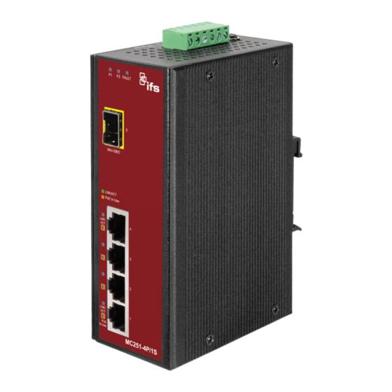
Page 9: Front Panel
The Flow Control function allows Industrial Fast Ethernet Switch supported routers and servers to directly connect to this device for fast, reliable data transfer. Front Panel The figure below shows the front panel of the MC251-4P/1S and the NS2051-4P/1T. IFS MC251-4P/1S and NS2051-4P/1T User Manual... -
Page 10: Led Indicators
Indicates that the Switch is actively sending Blink or receiving data over that port. PoE Port Color Function PoE In Indicates that the port is providing 48V DC in-line Orange power. (Ports 1-4) IFS MC251-4P/1S and NS2051-4P/1T User Manual... -
Page 11: Top Panel
1. Insert positive / negative DC power wires into the contacts 1 and 2 for POWER 1, or 5 and 6 for POWER 2. V1- V1+ V2- V2+ 2. Tighten the wire-clamp screws to prevent the wires from disconnecting. IFS MC251-4P/1S and NS2051-4P/1T User Manual... -
Page 12: Wiring The Fault Alarm Contact
MC251-4P/1S and the NS2051-4P/1T will detect the fault status of the power failure and then forms an open circuit. The following illustration shows an application example for wiring the fault alarm contacts. Insert the wires into the fault alarm contacts IFS MC251-4P/1S and NS2051-4P/1T User Manual... -
Page 13: Mounting Installation
Mounting to a DIN-Rail The DIN-Rail kit comes assembled on the MC251-4P/1S and the NS2051-4P/1T out of the box. Please refer to following figures to hang the MC251-4P/1S and the NS2051-4P/1T on a DIN-Rail. IFS MC251-4P/1S and NS2051-4P/1T User Manual... - Page 14 2. Check that the DIN-Rail connector mount is tightly mounted on the track. 3. Please refer to following procedures to remove the MC251- 4P/1S and the NS2051-4P/1T from the track. IFS MC251-4P/1S and NS2051-4P/1T User Manual...
- Page 15 Mounting to a Wall To install the MC251-4P/1S and the NS2051-4P/1T on the wall, please follows the instructions described below. 1. Loosen the screws to remove the DIN Rail from the Media Converter. IFS MC251-4P/1S and NS2051-4P/1T User Manual...
- Page 16 3. Assemble the wall mount plate on the MC251-4P/1S and the NS2051-4P/1T. 4. Use the hook holes at the corners of the wall mount plate to hang the MC251-4P/1S and the NS2051-4P/1T on the wall. IFS MC251-4P/1S and NS2051-4P/1T User Manual...
-
Page 17: Application
Step 1: Unpack the Industrial Fast Ethernet Switch. Step 2: Check the DIN-Rail that is pre-installed on the Industrial Fast Ethernet Switch. (Please refer to DIN-Rail Mounting section for DIN-Rail installation. If you want to wall IFS MC251-4P/1S and NS2051-4P/1T User Manual... -
Page 18: Switch Operation
Switch Operation Address Table The Industrial Fast Ethernet Switch is implemented with an address table. This address table is composed of many entries. Each entry is used to store the address information of IFS MC251-4P/1S and NS2051-4P/1T User Manual... - Page 19 A Store-and-Forward Industrial Switch stores the incoming frames in an internal buffer and checks for any errors from the frames before transmission. Lack of error packet occurrence is important for an efficient and stable network.. IFS MC251-4P/1S and NS2051-4P/1T User Manual...
- Page 20 (usually at Power On or Reset). This is done by detecting the modes and speeds at the moment both devices are connected. IFS MC251-4P/1S and NS2051-4P/1T User Manual...
-
Page 21: Troubleshooting
Try another port on the Industrial Fast Ethernet Switch to make sure the cable is installed properly while making sure the cable is the right type Turn off the power and turn on the power again after waiting for awhile. IFS MC251-4P/1S and NS2051-4P/1T User Manual... -
Page 22: Specifications
1/2(+), 3/6(-) Assignment Switch Specification Switch Processing Store-and-Forward Scheme Address Table 2K entries Back Pressure for Half Duplex Flow Control IEEE 802.3x Pause Frame for Full Duplex Switch fabric 1Gbps Throughput (Packet per 0.74Mpps second) IFS MC251-4P/1S and NS2051-4P/1T User Manual... - Page 23 135mm x 87.8mm x 56mm Weight 842g Power Requirement 24 or 48V DC Installation DIN Rail Kit and Wall Mount Ear Power over Ethernet PoE Standard IEEE 802.3af Power over Ethernet / PSE Power Supply End-Span IFS MC251-4P/1S and NS2051-4P/1T User Manual...
- Page 24 Operating: -40 to 75 Degree C Temperature Storage: -40 to 85 Degree C Humidity Operating: 5~90%, Storage: 5~90% (Non-condensing) Regulation FCC Part 15 Class A, CE Compliance IEC60068-2-32 (Free Fall) Stability testing IEC60068-2-27 (Shock) IEC60068-2-6 (Vibration) IFS MC251-4P/1S and NS2051-4P/1T User Manual...
-
Page 25: Rj45 Pin Assignments
Not used Rx - (receive) Tx - (transmit) 7, 8 Not used RJ45 Cable Drawing The following figure shows the pin allocation and color of a straight cable, and connection of a crossover cable. IFS MC251-4P/1S and NS2051-4P/1T User Manual... - Page 26 Please make sure your connected cables are with same pin assignment and color as above picture before deploying the cables into your network. IFS MC251-4P/1S and NS2051-4P/1T User Manual...
-
Page 27: Contacting Technical Support
Technical Support Europe, Middle East and Africa Select Contact Us at www.utcfssecurityproducts.eu North America +1 855.286.8889 techsupport@interlogix.com Australia techsupport@interlogix.au IFS MC251-4P/1S and NS2051-4P/1T User Manual...