Table of Contents
Advertisement
Quick Links
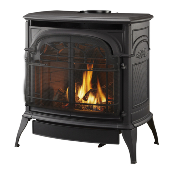
RADVT Series Radiance
Installation and Operating Instructions
Models:
RADVT(CS)CBSB, RADVT(CS)BSSB, RADVT(CS)BDSB, RADVT(CS)BMSB
WARNING:
FIRE OR EXPLOSION HAZARD
Failure to follow safety warnings exactly
could result in serious injury, death or
property damage.
•
Do not store or use gasoline or other
flammable vapors and liquids in the
vicinity of this or any other appliance.
•
WHAT TO DO IF YOU SMELL GAS
– Do not try to light any appliance.
– Do not touch any electrical switch; do
not use any phone in your building.
– Leave the building immediately.
– Immediately call your gas supplier from
a neighbor's phone. Follow the gas
supplier's instructions.
– If you cannot reach your gas supplier,
call the fire department.
•
Installation and service must be performed
by a qualified installer, service agency or
the gas supplier.
WARNING: Improper installation, adjustment,
alteration, service or maintenance can cause
injury or property damage. Refer to this manual.
For assistance or additional information consult
a qualified installer, service agency or the
gas supplier.
This appliance may be installed in an aftermarket,*
permanently located, manufactured home (USA
only) or mobile home, where not prohibited by
local codes.
This appliance is for use only with the type of gas
indicated on the rating plate. This appliance is
not convertible for use with other gases, unless
a certified kit is used.
* Aftermarket: Completion of sale, not for purpose of resale, from
the manufacturer.
Direct Vent Gas Heater
®
DANGER
A barrier designed to reduce the risk of burns from
the hot viewing glass is provided with this
appliance and shall be installed.
INSTALLER: Leave this manual with the appliance.
DANGER
CONSUMER: Retain this manual for
future reference.
CERTIFIED
S
B
AFETY
ARRIER
12697
Radiance cover
7/07
HOT GLASS WILL
CAUSE BURNS.
DO NOT TOUCH GLASS
UNTIL COOLED.
NEVER ALLOW CHILDREN
TO TOUCH GLASS.
20306759 12/14 Rev. 1
Un panneau vitré chaud peut
causer des brûlures.
Laissez refroidir le panneau
vitré avant d'y toucher.
Advertisement
Table of Contents
Troubleshooting

Related Manuals for Vermont Castings RADVT(CS)CBSB


Summary of Contents for Vermont Castings RADVT(CS)CBSB
- Page 1 RADVT Series Radiance Direct Vent Gas Heater ® Installation and Operating Instructions Models: RADVT(CS)CBSB, RADVT(CS)BSSB, RADVT(CS)BDSB, RADVT(CS)BMSB CERTIFIED WARNING: AFETY ARRIER FIRE OR EXPLOSION HAZARD Failure to follow safety warnings exactly could result in serious injury, death or property damage.
-
Page 2: Table Of Contents
Table of Contents PLEASE READ THE INSTALLATION & OPERATING INSTRUCTIONS BEFORE USING APPLIANCE. Thank you and congratulations on your purchase of a Vermont Castings stove. IMPORTANT: Read all instructions and warnings carefully before starting installation. Failure to follow these instructions may result in a possible fire hazard and will void the warranty. -
Page 3: Installation & General Information
Radiance Direct Vent Gas Heater ® Installation & Operating Instructions The Radiance Direct Vent Room Heater, Model Nos. RADVTCB, WARNING: Operation of this heater when not connected to a RADVTEB, RADVTBS, RADVTBD, RADVTBM, RADVTCSCB, properly installed and maintained venting system can result in carbon monoxide (CO) poisoning and possible death. -
Page 4: Massachusetts Residents Only
Radiance Direct Vent Gas Heater ® Installation & Operating Instructions Requirements for the Commonwealth of Inspection Massachusetts The state or local gas inspector of the side wall horizontally vented gas fueled equipment shall not approve the All gas fitting and installation of this heater shall only be installation unless, upon inspection, the inspector observes done by a licensed gas fitter or licensed plumber. -
Page 5: Stove Dimensions
Radiance Direct Vent Gas Heater ® Radiance Direct Vent Stove Dimensions 7" Outer Dia. 7" Outer Dia. See Page 7 for Flue Collar (178 mm) (178 mm) Centerline Dimensions. 14⁷⁄₈" 14⁷⁄₈" Supply Inlet Supply Inlet (378 mm) (378 mm) 4³⁄₄" 4³⁄₄"... -
Page 6: Installation Requirements
Radiance Direct Vent Gas Heater ® Installation Requirements The installation must conform with local codes or, in the absence of local codes, with the National Fuel Gas Code, Direct Vent System Only ANSI Z223.1/NFPA 54 - latest edition. (EXCEPTION: Do not derate this appliance for altitude. -
Page 7: Parallel Installation
Sidewall Clearance Direct Vent 6" (150 mm) Min. Clrnc * needed for installing DuraVent Minimum Vent Kit #2792 or Vermont Castings Group Minimum Vent Kit #7TFSMSK. 9/28/00 djt ST101b Fig. 6 Dimensions and clearances to ceiling or alcove. Hearth Requirements The Radiance Heater must be installed on rigid flooring. -
Page 8: Gas Specifications
Manifold Pressure 3.5" w.c. 10" w.c. The installation of your Vermont Castings stove must conform with local codes, or in the absence of local codes, with the National Fuel Gas Code ANSI Z223.1/ NFPA 54 - latest edition, or CSA B149.1 Installation code. -
Page 9: Vertical Termination
Radiance Direct Vent Gas Heater ® Restrictor Plate Adjustment Vertical Termination for Extended Pipe Runs A vertical vent system must terminate no less than 8’ (2.44 m) and no more than 40’ (12 m) above the appliance flue The Radiance stove is shipped with a restrictor plate in collar. -
Page 10: Vent Termination Clearances
Some of the most common clearances to keep in mind are shown in Figure 11. • Vermont Castings Group does not require any open- ing for inspection of vent pipe. Important: All vent clearances must be maintained. -
Page 11: General Venting Information - Termination Location
2. The special venting system used on Direct Vent Stoves are certified as part of the appliance, with clearances tested and approved by the list- ing agency. 3. Vermont Castings Group assumes no responsibility for the improper performance of the appliance when the venting system does not meet these requirements. -
Page 12: Termination Clearances
Radiance Direct Vent Gas Heater ® Termination Clearances Termination clearances for buildings with combustible and noncombustible exteriors. Inside Corner Alcove Applications* Outside Corner Combustible 6" (152 mm) Combustible 6" (152 mm) Noncombustible 2" (51 mm) Noncombustible 2" (51 mm) Balcony - Balcony - with no side wall with perpendicular side wall... -
Page 13: Venting Requirements And Options
These parts are 90° Elbow, Blk. 4DT-EL90B available from DuraVent Corporation, Selkirk Corporation 45° Elbow, Blk. 4DT-EL45B or your Vermont Castings Dealer. 6" Straight, Blk. 4DT-06B 9" Straight, Blk. 4DT-09B See Figure 4 for dimensions relevant to the standard mini- 4"... - Page 14 Direct Vent Gas Heater ® Twist Lock 12" Straight Pipe (CG) 7TFSDVP12 Vermont Castings Group Vent Components (1) 12" Non-adjustable Pipe The following kits are available to meet the needs of most Twist Lock 12" - 18" Adjustable Pipe 7TFSDVP1218 installations.
-
Page 15: Assembly Procedures
Radiance Direct Vent Gas Heater ® Assembly Procedures WARNING Failure to position the parts in accor- dance with these diagrams or failure to use only parts specifically approved for use with this heater may result in property damage or personal injury. This heater and components are heavy. -
Page 16: Install Optional Fan
Radiance Direct Vent Gas Heater ® WARNING This appliance is equipped with a three-prong (grounded) plug for your protection against shock hazard and should be plugged directly into a properly grounded three-prong receptacle. Do not cut or remove the grounding prong from this plug. Install the Optional Fan - RADVT Series If you are installing the optional convection Fan Kit #2767 (FK26), continue here. -
Page 17: Venting System Assembly - Direct Vent
For Canadian installations: The venting system must conform to the current CSA B149.1 installation code. Install the Vent Adapter Pipe (Vermont Castings Group Vent Components) 1. Attach Inner Starter Pipe, (found in the Parts Bag), ST648a to the next section of inner pipe. -
Page 18: Side Wall Termination Assembly
ST649 size shown in Figure 24. Combustible wall openings must be framed as shown in Figure 24. Fig. 22 DuraVent - install inner adpater pipe. Vermont Castings Group System ⁄ " (240mm) ⁄... - Page 19 Fig. 25 Assemble the wall sleeve and firestop. 9. Connect the horizontal pipe to the elbow. Fasten the ST215 wall plate to the pipe with three sheet metal screws. 4. For Vermont Castings Group Vent Pipe only: If nec- ZCS103 Zero Clearance Sleeve measure thru wall...
-
Page 20: Vent Termination Below Grade
Radiance Direct Vent Gas Heater ® 11. For Vermont Castings Group only: Install Charcoal Wall Screws Gray Pipe Rings (#7FSDRG) or Polished Brass Pipe Rings and Anchors Waterproof Seal (#7FSDRP) at pipe joints, if desired. Around Pipe Snorkel Firestop Termination... -
Page 21: Selkirk Direct-Temp Metalbestos Direct Vent System
Radiance Direct Vent Gas Heater ® Selkirk Direct-Temp Metalbestos #7DVAIS Direct Vent System Attic Insulation Shield Installation Instructions 1. Determine whether the length of pipe fits the appliance outlet by attempting to engage the parts. If the parts engage smoothly, proceed to Step 2. If obstructions, #7DVFS Use Four Firestop in Up-... - Page 22 Radiance Direct Vent Gas Heater ® Gasket A round trim plate (TP) is attached to the ceiling, using screws, to provide a finished appearance once installed. (Fig. 35) Outlet End Inlet End Lock Tab To Termination To Appliance Ceiling Support ST922 Ceiling Support Collar...
- Page 23 Radiance Direct Vent Gas Heater ® The Cathedral Ceiling Support (CCS) may be used in Supporting DIRECT-TEMP: Horizontal Support pitched or flat ceiling installations and comes with a sup- Horizontal runs of Direct-Temp should be supported ev- port collar and a decorative two part square trim plate. In- ery 4’...
- Page 24 Radiance Direct Vent Gas Heater ® less than 7’ (2.1 m) high. Refer to Pages 11, 12, Figures Wall Thimble Shield 11, 12 for more detail. Seal with RTV Silicone Sealant Wall Snorkel Termination on Exterior side Thimble here (around Shield perimeter) Window Well...
-
Page 25: Vertical Installation
Radiance Direct Vent Gas Heater ® ed straps of the horizontal termination provide a method Vertical Termination of attachment. These can either be threaded through the opening or wall thimble (if used) and screwed to the pipe or removed with a pair of tin snips if not used. Use proper Storm Collar masonry fasteners to attach the horizontal termination to Approved Silicone... -
Page 26: Install Log Set
Radiance Direct Vent Gas Heater ® 11. Add lengths of pipe and firestop as necessary until over the pipe protruding through the roof. Recheck ori- assembly extends to a point above the roof which com- entation and use a silicone sealant around and under the plies with local code requirements for minimum termina- perimeter of the flashing where it is in contact with the tion height and with the appliance manufacturer’s installa-... - Page 27 Radiance Direct Vent Gas Heater ® CAUTION: Before installation, inspect ember Rear Log bed burner for damage. Do not use ember bed if damaged or cracked. NOTE: Small, shallow surface cracks are acceptable. Figure 48 1. Remove the logs from their packaging and inspect each piece for damage.
-
Page 28: Connect Gas Supply Line
5.5" w.c. and maximum of 14.0" w.c. The appliance must only use the gas specified on the rat- ing plate, unless converted using a Vermont Castings Fuel In order to connect Propane, use a fitting with 1/2" Conversion Kit. To convert from Natural Gas to LP use Kit NPT on the valve side and 1/2"... -
Page 29: Install On/Off Switch
Radiance Direct Vent Gas Heater ® Thermostat Connection (optional) THIS APPLIANCE SHOULD BE CONNECTED TO THE GAS SUPPLY ONLY BY A QUALIFIED Use only a thermostat rated for 500 - 750 millivolts. GAS SERVICE TECHNICIAN. FOLLOW ALL LOCAL CODES. Check the table below for the appropriate gauge ther- mostat wire to use for the length of lead required in your THERE MUST BE A GAS SHUT-OFF BETWEEN installation. -
Page 30: Install The Safety Barrier
Radiance Direct Vent Gas Heater ® Install the Safety Barrier CERTIFIED AFETY ARRIER NOTE: A barrier designed to reduce the risk of burns from the hot viewing glass is provided with this appliance and shall be installed for the protection of Bottom children and other at risk individuals. -
Page 31: Operation
Radiance Direct Vent Gas Heater ® Operation The Radiance is operated with the front plate in place with Flame & Temperature Adjustment the doors open or closed. To open the front doors, pull forward to separate the magnetic catch. For stoves equipped with HI/LO valves, flame adjustment is accomplished by rotating the HI/LO adjustment knob located near the center of the gas control valve. -
Page 32: Lighting And Operating Instructions
Radiance Direct Vent Gas Heater ® Lighting and Operating Instructions FOR YOUR SAFETY READ BEFORE LIGHTING WARNING:If you do not follow these instructions exactly, a fire or explosion may result causing property damage, personal injury or loss of life. A. This heater has a pilot which must be lit manually. When C. -
Page 33: Troubleshooting - Sit Nova 820 (Radvt Series)
Radiance Direct Vent Gas Heater ® Troubleshooting the Gas Control System (RADVT Series) SIT NOVA 820 MILLIVOLT VALVE NOTE: Before trouble shooting the gas control system, be sure external gas shut off is in the “On" position. Possible Causes Symptom Corrective Action 1. -
Page 34: Instructions For Rcsitea
Radiance Direct Vent Gas Heater ® Instructions for RCSITEA Remote Transmitter RADVTCS Series Install Batteries CAUTION: The RCSITEA is only certified for use on vent- The remote transmitter uses three (3) “AAA" batteries. ed heater rated equipment. 1. Press down the battery door tab and pull out to remove This remote control system provides a safe, reliable and the battery door. - Page 35 Radiance Direct Vent Gas Heater ® 3. To check, press either the ON or OFF button on the Reset Button transmitter and the receiver indicator light will blink. If The reset button can be used to reset the transmitter if not, repeat Step 2.
- Page 36 Radiance Direct Vent Gas Heater ® Initial Startup 4. There will be a slight delay in the response of the unit (on/off) to a temperature. Room temperature is moni- Figure 62 tored every three (3) minutes. 1. After initial power up or 5.
- Page 37 Radiance Direct Vent Gas Heater ® Transmitter Thermal Shutdown minutes. 2. Use the ON /s button to Figure 70 set the desired On Delay 1. If transmitter measures a Time from 0 to 15 minutes. room temperature exceed- 3. Use the OFF / t button to ing 99°...
-
Page 38: Troubleshooting Rcsitea
Radiance Direct Vent Gas Heater ® Testing Remote Control System 1. Light the gas appliance following the lighting instruc- tions on Page 32. Confirm the pilot light is on; it must be in operation for the remote control to operate the main gas valve and blower. -
Page 39: Fuel Conversion Instructions
Radiance Direct Vent Gas Heater ® Fuel Conversion Instructions 2. Allow the valve to WARNING! This conversion kit shall be installed cool to room tem- by a qualified service agency in accordance with perature. Figure 72 the manufacturer’s instructions and all applicable Figure 3. - Page 40 Radiance Direct Vent Gas Heater ® RADVTCS Series Models 2. Replace pilot orifice. 3. Remove pilot hood by lifting up. (Fig. 79) Do not remove 1. Using the TORX T20 bit remove and discard the three the snap ring to remove the pilot hood. NOTE: It is not (3) pressure regulator mounting screws from the old necessary to remove the pilot tube for conversion.
- Page 41 Radiance Direct Vent Gas Heater ® Orifice Orifice Venturi Bracket Bracket Orifice Air Shutter Bracket CO142 Fig. 84 The air shutter setting is 1/2" (13 mm) from the orifice Pem Studs ST919 bracket to the edge of the air shutter. Fig.
- Page 42 Radiance Direct Vent Gas Heater ® Table 2. Injector Orifice Size Matrix Conversion to LP Input (BTU/h) Model Kit # Orifice Part # Minimum Maximum RADVT 20012729 1.75 mm 20012946 25,000 36,000 RADVTCS 20300165 Conversion to Natural Gas Input (BTU/h) Model Kit # Orifice...
-
Page 43: Maintenance
Radiance Direct Vent Gas Heater ® Maintenance Your Radiance Gas Heater will provide years of service with Cleaning the Glass minimal upkeep. The following procedures will help ensure WARNING: Allow the glass to cool completely that your stove continues to function properly. before attempting to clean. -
Page 44: Glass Replacement
Do not use your stove if the flame pattern differs from that The Radiance Gas Heater uses a ‘tadpole’ type gasket to shown here. Contact your Vermont Castings dealer or a seal between the glass panel and the frame. In time, this qualified technician for help. -
Page 45: Wiring Diagrams
Radiance Direct Vent Gas Heater ® Wiring Diagrams - RADVT POWER CORD On/Off Switch Wiring TP/TH Millivolt Chassis Gas Valve Ground Black ST124b Thermostat Thermostat Optional Thermostat (Optional) (Optional) Wiring FAN JUNCTION BOX St124b on/off/switch wiring Strain Relief TP/TH 1/11/00 djt ON / OFF Millivolt Rheostat... - Page 46 Radiance Direct Vent Gas Heater ® Wiring Diagrams - RADVTCS Black 120V AC Adapter Black mV Valve Receiver T P / T H 120V AC Plug Female Male SIT HI / LO 120V AC Valve Blower ST1091 Fig. 91 SIT Hi/Lo blower schematic. ST1090 120V AC Plug for Receiver SIT valve wiring...
-
Page 47: Replacement Parts
Radiance Direct Vent Gas Heater Replacement Parts 34a,b 35a,b,c 29 30 27a,b 26a,b 4967 Vermont Castings Group reserves the right to make changes in design, materials, specifications, prices and discontinue colors and products at any RADVT/RADVTCS parts time, without notice. 8/09 djt 20306759... - Page 48 Radiance Direct Vent Gas Heater ® Radiance Direct Vent Gas Heater (continued) Replacement Parts Ref. Description RADVT/RADVTCS Log Set - Complete 20012550 Log, Rear 20012541 Log, Right Front 20012543 Log, Left Front 20012542 Left Cross Log 20012544 Right Cross Log 20012545 Ember Bed Assembly 20012206...
- Page 49 Radiance Direct Vent Gas Heater ® Radiance Direct Vent Gas Heater (continued) Replacement Parts Ref. Description RADVT/RADVTCS Ignitor Piezo w/ Nut SIT 057958 Bracket Piezo Ignitor/Control (not shown) 20010876 Manifold Assembly 20012202 Air Shutter Assembly 20012204 Trim ON/OFF Switch 30000874 Remote Kit (Hi/Lo, Blower) (RADVTCS Series only) RCSITEA Wire w/ Straight Term 2 End 50"...
-
Page 50: Optional Accessories
Radiance Direct Vent Gas Heater ® Optional Accessories Fan Kits - RADVT Series Screen Kit FK26 Fan An optional screen, R40SK, for use with the operable doors is available to allow the doors to be left in the open position. The FK26 fan helps distribute heated air from within the firebox out into the room. -
Page 51: Warranty
® LIMITED LIFETIME WARRANTY PRODUCT COVERED BY THIS WARRANTY All Vermont Castings brand gas stoves, gas inserts, and gas fireplaces installed in the United States of America or Canada. LIMITED LIFETIME WARRANTY Vermont Castings Group warrants that all cast iron parts, the •... - Page 52 EFFICIENCY RATINGS ENERGUIDE RATINGS FIREPLACE EFFICIENCY D.O.E. MODEL PERCENTAGE (AFUE PERCENTAGE) RADVT Series 66.0 68.4 RADVTCS Series 66.0 68.4 149 Cleveland Drive • Paris, Kentucky 40361 www.vermontcastingsgroup.com...