Vermont Castings Radiance RADVTCB Homeowner's Installation And Operating Manual
Direct vent gas heater
Hide thumbs
Also See for Radiance RADVTCB:
- Homeowner's installation & operating manual (52 pages) ,
- Homeowner's installation and operating manual (52 pages) ,
- Homeowner's installation and operating manual (52 pages)
Table of Contents
Advertisement
Quick Links
INSTALLER / CONSUMER
SAFETY INFORMATION
PLEASE READ THIS MANUAL
BEFORE INSTALLING AND USING
APPLIANCE.
WARNING!
IF THE INFORMATION IN THIS
MANUAL IS NOT FOLLOWED
EXACTLY, A FIRE OR EXPLOSION
MAY RESULT CAUSING
PROPERTY DAMAGE, PERSONAL
INJURY OR LOSS OF LIFE.
FOR YOUR SAFETY
Installation and service must be
performed by a qualified installer,
service agency or the gas suppler.
WHAT TO DO IF
YOU SMELL GAS:
•
Do not try to light any appliance.
•
Do not touch any electric switch; do
not use any phone in your building.
•
Immediately call your gas supplier
from your neighbor's phone. Follow
the gas supplier's instructions.
•
If you cannot reach your gas supplier,
call the fire department.
DO NOT STORE OR USE
GASOLINE OR OTHER
FLAMMABLE VAPORS AND
LIQUIDS IN THE VICINITY OF THIS
OR ANY OTHER APPLIANCE.
This appliance may be installed in an
after market permanently located
manufactured (mobile) home where not
prohibited by local codes.
This appliance is only for use with the
type of gas indicated on the rating plate.
This appliance is not convertible for use
with other gases unless a certified kit is
used.
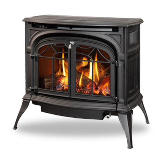
Radiance
Direct Vent Gas Heater
Models:
RADVT Series: RADVTCB, RADVTEB, RADVTMB,
RADVTBS, RADVTCH, RADVTVG, RADVTBD, RAD-
VTBB, RADVTCG, RADVTGG, RADVTSG,
RADVTC Series: RADVTCCB, RADVTCEB,
RADVTCMB, RADVTCBS, RADVTCCH, RADVTCVG,
RADVTCBD, RADVTCBB, RADVTCCG, RADVTCSG
Homeowner's Installation
and Operating Manual
INSTALLER: Leave this manual with the appliance.
CONSUMER: Retain this manual for future reference.
12697
Radiance cover
7/07
C E RT I F I E D
20012697 1/08 Rev. 3
Advertisement
Table of Contents

Related Manuals for Vermont Castings Radiance RADVTCB


Summary of Contents for Vermont Castings Radiance RADVTCB
- Page 1 INSTALLER / CONSUMER SAFETY INFORMATION PLEASE READ THIS MANUAL BEFORE INSTALLING AND USING APPLIANCE. Radiance WARNING! Direct Vent Gas Heater IF THE INFORMATION IN THIS MANUAL IS NOT FOLLOWED Models: EXACTLY, A FIRE OR EXPLOSION RADVT Series: RADVTCB, RADVTEB, RADVTMB, MAY RESULT CAUSING RADVTBS, RADVTCH, RADVTVG, RADVTBD, RAD- PROPERTY DAMAGE, PERSONAL...
-
Page 2: Table Of Contents
Table of Contents PLEASE READ THE INSTALLATION & OPERATING INSTRUCTIONS BEFORE USING APPLIANCE. Thank you and congratulations on your purchase of a Vermont Castings stove. IMPORTANT: Read all instructions and warnings carefully before starting installation. Failure to follow these instructions may result in a possible fire hazard and will void the warranty. -
Page 3: Installation & General Information
Radiance Direct Vent Gas Heater Installation & Operating Instructions The Radiance Direct Vent Room Heater, Model Nos. RADVTCB, This appliance is approved for bedroom installations in the U.S. RADVTEB, RADVTMB, RADVTBS, RADVTCH, RADVTVG, and Canada. RADVTBD, RADVTBB, RADVTCG, RADVTGG, RADVTSG, This appliance may be installed in an aftermarket* manufactured RADVTCCB, RADVTCEB, RADVTCMB, RADVTCBS, RAD- (mobile) home, where not prohibited by state or local codes. -
Page 4: Operating Instructions Installation Requirements For The Commonwealth Of Massachusetts
Radiance Direct Vent Gas Heater Installation & Operating Instructions Requirements for the Commonwealth of Inspection Massachusetts The state or local gas inspector of the side wall horizontally vented gas fueled equipment shall not All gas fitting and installation of this heater shall only be approve the installation unless, upon inspection, the done by a licensed gas fitter or licensed plumber. -
Page 5: Stove Dimensions
Radiance Direct Vent Gas Heater Radiance Direct Vent Stove Dimensions 7" Outer Dia. 7" Outer Dia. See Page 7 for Flue Collar (178 mm) (178 mm) 14���" 14���" Centerline Dimensions. Supply Inlet Supply Inlet (378 mm) (378 mm) 4���" 4���" 9���"... -
Page 6: Installation Requirements
Radiance Direct Vent Gas Heater Installation Requirements The installation must conform with local codes or, in the absence of local codes, with the National Fuel Gas Direct Vent System Only Code, ANSI Z223.1/NFPA 54 - latest edition. (EXCEP- TION: Do not derate this appliance for altitude. Main- tain the manifold pressure at 3.5”... -
Page 7: Parallel Installation
Radiance Direct Vent Gas Heater Wall Centerline from Floor Parallel Installation: Minimum Clearance and Flue Centerline Direct Vent Only 42" (1070mm) Min. Alcove Width 4" (102mm) 48" (1220mm) Max. Alcove Depth 6" 6" (150mm) (150mm) ST130 Fig. 3 Parallel installation, minimum back and side clear- ances, and flue centerlines. -
Page 8: Gas Specifications
14.0” w.c. 14.0” w.c. Manifold Pressure 3.5” w.c. 10” w.c. �� The installation of your Vermont Castings stove �� must conform with local codes, or in the absence of �� local codes, with the National Fuel Gas Code ANSI ��... -
Page 9: Vertical Termination
Radiance Direct Vent Gas Heater Restrictor Plate Adjustment Vertical Termination for Extended Pipe Runs A vertical vent system must terminate no less than 8’ (2.44 m) and no more than 40’ (12 m) above the ap- The Radiance stove is shipped with a restrictor plate pliance flue collar. -
Page 10: Vent Termination Clearances
Radiance Direct Vent Gas Heater Vent Termination Clearances When planning the installation, consider the location Your stove is approved to be vented either through the of the vent terminal and clearances. Some of the most side wall, or vertical through the roof. common clearances to keep in mind are shown in Figure •... -
Page 11: General Venting Information - Termination Location
Radiance Direct Vent Gas Heater General Venting Information - Termination Location INSIDE CORNER DETAIL ����� ������ Fixed Operable Closed CFM145a AREA WHERE TERMINAL IS NOT PERMITTED VENT TERMINATION AIR SUPPLY INLET Canadian Installations US Installations CFM145a A = Clearance above grade, veranda, porch, 12”... -
Page 12: Termination Clearances
Radiance Direct Vent Gas Heater Termination Clearances Termination clearances for buildings with combustible and noncombustible exteriors. Inside Corner Alcove Applications* Outside Corner Combustible 6" (152 mm) Combustible 6" (152 mm) Noncombustible 2" (51 mm) Noncombustible 2" (51 mm) Balcony - Balcony - with no side wall with perpendicular side wall... -
Page 13: Venting Requirements And Options
These 90° Elbow, Blk. 4DT-EL90B parts are available from DuraVent Corporation, Selkirk 45° Elbow, Blk. 4DT-EL45B Corporation or your Vermont Castings Dealer. 6” Straight, Blk. 4DT-06B 9” Straight, Blk. 4DT-09B See Figure 4 for dimensions relevant to the standard 4”... - Page 14 Radiance Direct Vent Gas Heater and all of the other Vertical Termination parts. Vertical Termination Cap 4DT-VC Twist Lock 12” Straight Pipe (CG) 7TFSDVP12 CFM Vent Components (1) 12” Non-adjustable Pipe The following kits are available to meet the needs of Twist Lock 12”...
-
Page 15: Assembly Procedures Tools Required
Radiance Direct Vent Gas Heater Assembly Procedures WARNING Failure to position the parts in accor- dance with these diagrams or failure to use only parts specifically approved for use with this heater may result in property dam- age or personal injury. This heater and components are heavy. -
Page 16: Install Optional Fan
Radiance Direct Vent Gas Heater WARNING This appliance is equipped with a three-prong (grounded) plug for your protection against shock hazard and should be plugged directly into a properly grounded three-prong receptacle. Do not cut or remove the grounding prong from this plug. Install the Optional Fan If you are installing the optional convection Fan Kit #2767 (FK26), continue here. -
Page 17: Venting System Assembly - Direct Vent
Radiance Direct Vent Gas Heater Venting System Assembly General Information The Radiance is approved for installation only with the vent components listed on Pages 12 and 13. Follow the vent component instructions exactly. For U.S. installations: The venting system must con- form with local codes and/or the current National Fuel Gas Code, ANSI Z223.1/NFPA 54. -
Page 18: Install Vent Adapter Pipe (Selkirk Corporation Components)
Radiance Direct Vent Gas Heater minimum of 1¹⁄₂” over the flue outlet. The outside of the Direct-Temp Length will fit inside the flue outlet Inner Adpater Pipe 1/4-20 x Secure with a minimum of two #8 x 1/4” sheet metal 3/8”... - Page 19 Radiance Direct Vent Gas Heater 12” (305mm) Sleeve Max. Length #8 Sheet Metal Screws ST215 Fig. 27 Measure the horizontal length. sleeve. Seal the joint inside the wall plate if needed Firestop ZCS103 to keep cold air from being drawn into the home. Fig.
-
Page 20: Vent Termination Below Grade
Radiance Direct Vent Gas Heater 11. For CFM only: Install Charcoal Gray Pipe Rings Wall Screws (#7FSDRG) or Polished Brass Pipe Rings (#7FSDRP) and Anchors Waterproof Seal at pipe joints, if desired. Around Pipe Snorkel Firestop Termination Vent Termination Below Grade Install Snorkel Kit #7FSDVSKS when it is not possible to meet the required vent termination clearances of 12”... -
Page 21: Selkirk Direct-Temp Metalbestos Direct Vent System
Radiance Direct Vent Gas Heater Selkirk Direct-Temp Metalbestos Direct #7DVAIS Vent System Attic Insulation Shield Installation Instructions 1. Determine whether the length of pipe fits the appli- ance outlet by attempting to engage the parts. If the parts engage smoothly, proceed to Step 2. If ob- #7DVFS Use Four Firestop in... - Page 22 Radiance Direct Vent Gas Heater it by screwing the support plate to the top of the prop- Gasket erly framed ceiling joist opening, using screws provided. A round trim plate (TP) is attached to the ceiling, using screws, to provide a finished appearance once in- Outlet End Inlet End stalled.
-
Page 23: Horizontal Installation
Radiance Direct Vent Gas Heater The Cathedral Ceiling Support (CCS) may be used in Supporting DIRECT-TEMP: Horizontal Support pitched or flat ceiling installations and comes with a Horizontal runs of Direct-Temp should be supported support collar and a decorative two part square trim every 4’... - Page 24 Radiance Direct Vent Gas Heater from traffic areas such as walkways if it is less than 7’ Wall Thimble (2.1 m) high. Refer to Pages 10, 11, Figures 11, 12 for Shield more detail. Seal with RTV Silicone Sealant Wall Snorkel Termination on Exterior side Thimble...
- Page 25 Radiance Direct Vent Gas Heater If the wall is brick or concrete, and contains no com- Vertical Termination bustible material, a 7” (178 mm) round penetration hole is adequate. The wall thimble is not required. The perforated straps of the horizontal termination provide Storm Collar a method of attachment.
-
Page 26: Install Log Set
Radiance Direct Vent Gas Heater the assembled pipe to the appliance. Determine and NOTE: Whenever DIRECT-TEMP penetrates through a mark the location of where the support collar will be at- ceiling, a floor or a wall, it must be firestopped. tached to the pipe. - Page 27 Radiance Direct Vent Gas Heater Rear Log 2. Install the rear log by plac- ing it on the ember bed Figure 48 toward the back of the firebox. (Fig. 48) The log should touch the back wall of the firebox. When the log is in place, the two (2) notches on the bottom of the log rest on the two (2)
-
Page 28: Connect Gas Supply Line
5.5” w.c. and maximum of 14.0” w.c. The appliance must only use the gas specified on the rating plate, unless converted using a Vermont Castings In order to connect Propane, use a fitting with 1/2” Fuel Conversion Kit. To convert from Natural Gas to LP NPT on the valve side and 1/2”... -
Page 29: Install On/Off Switch
Radiance Direct Vent Gas Heater THIS APPLIANCE SHOULD BE CON- NECTED TO THE GAS SUPPLY ONLY BY A QUALIFIED GAS SERVICE TECHNICIAN. FOLLOW ALL LOCAL CODES. THERE MUST BE A GAS SHUT-OFF BE- TWEEN THE STOVE AND THE SUPPLY. Install ON/OFF Switch The switch assembly parts are found in the parts bag. -
Page 30: Flame & Temperature Adjustment
Radiance Direct Vent Gas Heater Turn Turn clockwise counterclockwise to decrease to increase flame height flame height Fig. 55 Flame adjustment knob for SIT valve. Pilot As- Flame Characteristics sembly FP390 ST476 It is important to periodically perform a visual check FLAME ADJUSTMENT KNOB 11/21/96 of the pilot and the burner flames. -
Page 31: Lighting And Operating Instructions
Radiance Direct Vent Gas Heater Lighting and Operating Instructions FOR YOUR SAFETY READ BEFORE LIGHTING WARNING:If you do not follow these instructions exactly, a fire or explosion may result causing property damage, personal injury or loss of life. A. This heater has a pilot which must be lit manu- •... -
Page 32: Troubleshooting - Sit Nova 820 (Radvt Series)
Radiance Direct Vent Gas Heater Troubleshooting the Gas Control System (RADVT Series) SIT NOVA 820 MILLIVOLT VALVE NOTE: Before trouble shooting the gas control system, be sure external gas shut off is in the “On” position. Possible Causes Symptom Corrective Action 1. -
Page 33: Instructions For Rf Comfort Control Valve
Radiance Direct Vent Gas Heater 7. If the manual switch is in the LOCAL position, the Instructions for Comfort Control Valve valve will be at the highest fixed pressure setting RADVTC Series and the fan will be at the highest fixed speed. The The Comfort Control valve allows remote control of transmitter will control the fan only. - Page 34 Radiance Direct Vent Gas Heater Auto Mode Pilot As- sembly In the AUTO mode, the room temperature, set tem- perature, flame and fan levels will be shown. AUTO will appear next to both the flame and fan icons. Blower When the control is in the AUTO mode, the main burner will turn on/off or modulate based on the heat needed to maintain the set temperature.
- Page 35 Radiance Direct Vent Gas Heater Comfort Control Valve System Sequence of Operation with Transmitter Set manual switch Five minute wait to local or remote period Light pilot burner Review LED fail- Did the LED stop ure analysis. blinking? Release pilotstat knob.
- Page 36 Radiance Direct Vent Gas Heater Auto Path If the manual switch is set to REMOTE, Move switch from press the mode button LOCAL to REMOTE. to display AUTO on the Press any key within transmitter. Does the 30 seconds. transmitter display the room and temperture setting? If the settings is above...
-
Page 37: Fuel Conversion Instructions
Radiance Direct Vent Gas Heater Fuel Conversion Instructions 2. Allow the valve WARNING! This conversion kit shall be installed to cool to room by a qualified service agency in accordance with temperature. Figure 61 the manufacturer’s instructions and all applicable Figure 3. -
Page 38: Gas Conversion
Radiance Direct Vent Gas Heater 2. Remove and replace plug on lower right hand side Pilot Hood of the valve; Red for LP and Blue for NG. (Page 32, Fig. 57) 3. Remove motor top cap using a standard slotted screwdriver. - Page 39 Radiance Direct Vent Gas Heater 3. Remove injector orifice from left burner bracket with a 1/2” wrench. Use a back up wrench to prevent damage to the manifold. (Fig. 74) Pilot Orifice CO1044 Fig. 71 Remove pilot orifice. Burner Orifice Conversion 1.
- Page 40 Radiance Direct Vent Gas Heater 5. Replace glass and stove front. 6. Restore gas to system and relight appliance accord- ing to Lighting Instructions on Page 31. 7. Leak check the system using a gas leak detector solution. 8. Relight the main burner in both the “HI” and “LO” po- sitions to verify proper burner ignition and operation.
-
Page 41: Maintenance
Radiance Direct Vent Gas Heater Maintenance Your Radiance Gas Heater will provide years of service Cleaning the Glass with minimal upkeep. The following procedures will help ensure that your stove continues to function properly. WARNING: Allow the glass to cool com- pletely before attempting to clean. -
Page 42: Gasket Replacement
- 2” (25-50mm). Mark the spot to be cut. Use a utility Do not use your stove if the flame pattern differs from knife. that shown here. Contact your Vermont Castings dealer or a qualified technician for help. 3. Starting on a long edge, remove about 6” of the protective paper strip and apply the flat adhesive... -
Page 43: Wiring Diagrams
Radiance Direct Vent Gas Heater Wiring Diagrams POWER CORD On/Off Switch Wiring TP/TH Millivolt Gas Valve Chassis Ground Black ST124b Thermostat Thermostat (Optional) Optional Thermostat (Optional) Wiring FAN JUNCTION BOX St124b on/off/switch wiring Strain Relief TP/TH 1/11/00 djt ON / OFF Millivolt Rheostat Gas Valve... -
Page 44: Replacement Parts
Radiance Direct Vent Gas Heater 29 30 36a,b 35a,b 37a,b,c 26a,b • CFM Corporation reserves the right to make changes in design, materials, specifications, prices and discontinue colors and products at any time, 12697 without notice. RADVT/RADVTC parts 6/07 djt Radiance Direct Vent Gas Heater Models: RADVT Series: RADVTCB, RADVTEB, RADVTMB, RADVTBS, RADVTCH, RADVT- VG, RADVTBD, RADVTBB, RADVTC Series: RADVTCG, RADVTGG, RADVTSG, RADVTCCB,... - Page 45 Radiance Direct Vent Gas Heater Radiance Direct Vent Gas Heater (continued) Models: RADVT Series: RADVTCB, RADVTEB, RADVTMB, RADVTBS, RADVTCH, RADVTVG, RADVTBD, RADVTBB, RADVTC Series: RADVTCG, RADVTGG, RADVTSG, RADVTCCB, RADVTCEB, RADVTCMB, RADVTCBS, RADVTCCH, RADVTCVG, RADVTCBD, RADVTCBB, RADVTCCG, RADVTCSG Ref. Description RADVT/RADVTC Log Set - Complete 20012550 Log, Rear...
- Page 46 Radiance Direct Vent Gas Heater Radiance Direct Vent Gas Heater (continued) Models: RADVT Series: RADVTCB, RADVTEB, RADVTMB, RADVTBS, RADVTCH, RADVTVG, RADVTBD, RADVTBB, RADVTC Series: RADVTCG, RADVTGG, RADVTSG, RADVTCCB, RADVTCEB, RADVTCMB, RADVTCBS, RADVTCCH, RADVTCVG, RADVTCBD, RADVTCBB, RADVTCCG, RADVTCSG Ref. Description RADVT/RADVTC 35b.
- Page 47 Radiance Direct Vent Gas Heater Radiance Direct Vent Gas Heater (continued) Models: RADVT Series: RADVTCB, RADVTEB, RADVTMB, RADVTBS, RADVTCH, RADVTVG, RADVTBD, RADVTBB, RADVTC Series: RADVTCG, RADVTGG, RADVTSG, RADVTCCB, RADVTCEB, RADVTCMB, RADVTCBS, RADVTCCH, RADVTCVG, RADVTCBD, RADVTCBB, RADVTCCG, RADVTCSG Shell Enamel Parts - Radiance Direct Vent Enamel Model Left...
-
Page 48: Optional Accessories
Radiance Direct Vent Gas Heater Optional Accessories Fan Kits Screen Kit FK26 Fan An optional screen, R40SK, for use with the operable doors is available to allow the doors to be left in the The FK26 fan helps distribute heated air from within open position. - Page 49 Radiance Direct Vent Gas Heater 20012697...
- Page 50 Radiance Direct Vent Gas Heater 5050 20012697...
-
Page 51: Warranty
Radiance Direct Vent Gas Heater LIMITED LIFETIME WARRANTY PRODUCT COVERED BY THIS WARRANTY All Vermont Castings brand gas stoves, gas inserts, and gas fireplaces installed in the United States of America or Canada. LIMITED LIFETIME WARRANTY CFM Corporation (hereinafter referred to as CFM) warrants that all •... - Page 52 CFM Corporation 2695 Meadowvale Blvd. • Mississauga, Ontario, Canada L5N 8A3 800-668-5323 • www.cfmcorp.com...