Lexmark X422 Laser MFP Service Manual
Laser mfp
Hide thumbs
Also See for X422 Laser MFP:
- Technical reference manual (416 pages) ,
- User reference manual (250 pages) ,
- Setup manual (82 pages)
Table of Contents
Advertisement
Quick Links
• Table of Contents
• Start Diagnostics
• Safety and Notices
• Safety and Notices
• Trademarks
• Index
Revised: November 9, 2006
Lexmark™ X422 Laser MFP
Lexmark and Lexmark with diamond
design are trademarks of Lexmark
International, Inc., registered in the
United States and/or other countries.
7001–001
Advertisement
Table of Contents

Related Manuals for Lexmark X422 Laser MFP


Summary of Contents for Lexmark X422 Laser MFP
- Page 1 Revised: November 9, 2006 Lexmark™ X422 Laser MFP 7001–001 • Table of Contents • Start Diagnostics • Safety and Notices • Safety and Notices • Trademarks • Index Lexmark and Lexmark with diamond design are trademarks of Lexmark International, Inc., registered in the...
- Page 2 Lexmark, Lexmark with diamond design, MarkNet, MarkVision, and Optra are trademarks of Lexmark International, Inc., registered in the United States and/or other countries. ImageQuick, Optra Forms, and PictureGrade are trademarks of Lexmark International, Inc.
-
Page 3: Table Of Contents
7001-001 Table of Contents Laser notices ......... . . vii Safety information. - Page 4 7001-001 Service checks ........2-18 ADF service check .
- Page 5 7001-001 Adjustments ........4-2 Paper feed adjustment .
- Page 6 7001-001 Scanner cover removals ......4-67 Scanner ADF removal......4-75 Scanner ADF motor removal.
-
Page 7: Laser Notices
7001-001 Laser notices The following laser notice labels may be affixed to this MFP as shown: Laser advisory label Laser notices... -
Page 8: Laser Notice
7001-001 Laser Notice The printer is certified in the U.S. to conform to the requirements of DHHS 21 CFR Subchapter J for Class I (1) laser products, and elsewhere is certified as a Class I laser product conforming to the requirements of IEC 60825-1. - Page 9 7001-001 Avis relatif à l’utilisation de laser Pour les Etats-Unis : cette imprimante est certifiée conforme aux provisions DHHS 21 CFR alinéa J concernant les produits laser de Classe I (1). Pour les autres pays : cette imprimante répond aux normes IEC 60825-1 relatives aux produits laser de Classe I.
- Page 10 7001-001 Avisos sobre el láser Se certifica que, en los EE.UU., esta impresora cumple los requisitos para los productos láser de Clase I (1) establecidos en el subcapítulo J de la norma CFR 21 del DHHS (Departamento de Sanidad y Servicios) y, en los demás países, reúne todas las condiciones expuestas en la norma IEC 60825-1 para productos láser de Clase I (1).
- Page 11 7001-001 Laserinformatie De printer voldoet aan de eisen die gesteld worden aan een laserprodukt van klasse I. Voor de Verenigde Staten zijn deze eisen vastgelegd in DHHS 21 CFR Subchapter J, voor andere landen in IEC 60825-1. Laserprodukten van klasse I worden niet als ongevaarlijk aangemerkt.
- Page 12 7001-001 Huomautus laserlaitteesta Tämä kirjoitin on Yhdysvalloissa luokan I (1) laserlaitteiden DHHS 21 CFR Subchapter J -määrityksen mukainen ja muualla luokan I laserlaitteiden IEC 60825-1 -määrityksen mukainen. Luokan I laserlaitteiden ei katsota olevan vaarallisia käyttäjälle. Kirjoittimessa on sisäinen luokan IIIb (3b) 5 milliwatin galliumarsenidilaser, joka toimii aaltoalueella 770 - 795 nanometriä.
- Page 13 7001-001 Laser-melding Skriveren er godkjent i USA etter kravene i DHHS 21 CFR, underkapittel J, for klasse I (1) laserprodukter, og er i andre land godkjent som et Klasse I-laserprodukt i samsvar med kravene i IEC 60825-1. Klasse I-laserprodukter er ikke å betrakte som farlige. Skriveren inneholder internt en klasse IIIb (3b)-laser, som består av en gallium-arsenlaserenhet som avgir stråling i bølgelengdeområdet 770-795 nanometer.
- Page 14 7001-001 Japanese Laser Notice Chinese Laser Notice Service Manual...
- Page 15 7001-001 Korean Laser Notice Laser notices...
- Page 16 7001-001 Service Manual...
-
Page 17: Safety Information
7001-001 Safety information • The safety of this product is based on testing and approvals of the original design and specific components. The manufacturer is not responsible for safety in the event of use of unauthorized replacement parts. • The maintenance information for this product has been prepared for use by a professional service person and is not intended to be used by others. - Page 18 7001-001 Norme di sicurezza • La sicurezza del prodotto si basa sui test e sull'approvazione del progetto originale e dei componenti specifici. Il produttore non è responsabile per la sicurezza in caso di sostituzione non autorizzata delle parti. • Le informazioni riguardanti la manutenzione di questo prodotto sono indirizzate soltanto al personale di assistenza autorizzato.
- Page 19 7001-001 Pautas de Seguridad • La seguridad de este producto se basa en pruebas y aprobaciones del diseño original y componentes específicos. El fabricante no es responsable de la seguridad en caso de uso de piezas de repuesto no autorizadas. •...
- Page 20 7001-001 Informació de Seguretat • La seguretat d'aquest producte es basa en l'avaluació i aprovació del disseny original i els components específics. El fabricant no es fa responsable de les qüestions de seguretat si s'utilitzen peces de recanvi no autoritzades. •...
- Page 21 7001-001 Safety information...
-
Page 22: Preface
7001-001 Preface This manual contains maintenance procedures for service personnel. It is divided into the following chapters: 1. General information contains a general description of the MFP and the maintenance approach used to repair it. Special tools and test equipment are listed, as well as general environmental and safety instructions. -
Page 23: General Information
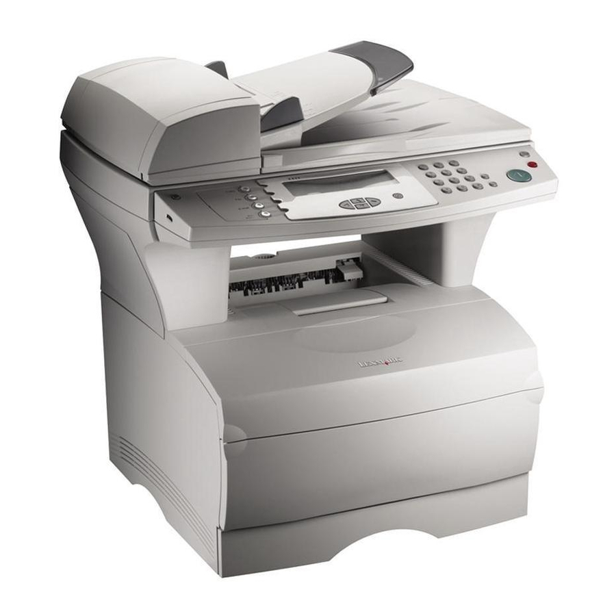
7001–001 1. General information The Lexmark™ X422 multifunction product (MFP), with 128MB of memory standard, a USB port, an integrated Ethernet adapter, and 33.6K baud fax/modem. This chapter provides an overview of the capabilities of the MFP and available options for each model. -
Page 24: Mfp Identification
7001–001 MFP identification Options “Options” on page 7-22 for a list of options available for the MFP. Service Manual... -
Page 25: Mfp Features
7001–001 MFP features Connectivity Attachments ✓ Standard USB interface ✓ Standard Ethernet 10/100 Base–TX ✓ Fax modem Note: ✓ Indicates attachment is part of the model factory shipped configuration. Fonts Fonts / options PCL bitmapped PCL outline PS outline PPDS bitmapped PPDS outline Note: There is no font card support. -
Page 26: Memory And User Flash Memory
7001–001 Memory and user flash memory Each model has a standard amount of memory (RAM) soldered on the system card, and a certain number of 100-pin DIMM slots available for installing additional memory or user flash memory options. Memory Standard memory 128MB Standard flash memory None... -
Page 27: Operator Panel
7001–001 Operator panel The operator panel consists of a 240 X 64 dot matrix APA LCD and 27 buttons. Four can be illuminated (copy, fax, e-mail and print/ profiles). The display can display eight lines of text with 40 characters each. Print area The following print area settings are available. -
Page 28: Print Media
7001–001 Print media The following table shows the supported media, media weights and media textures which together provide optimal print quality across a variety of media. Media ✓ Paper ✓ Card stock ✓ Transparency ✓ Labels ✓ Envelope ✓ Cotton paper ✓... -
Page 29: Data Streams
PCL 6 emulation includes the PCL 5e and PCL XL interpreters, and is fully compatible with Hewlett Packard’s LaserJet 5 Family. Furthermore, the MFP PCL emulation is backward compatible with the Lexmark T 520/522/620/622 and other members of Lexmark’s Optra™ family of laser printers. •... -
Page 30: Paper Handling
7001–001 Paper handling Paper handling Standard Standard input sources: • Integrated 250–sheet tray – The 250 sheet drawer supports the following sizes: A4, A5, JIS B5, folio, letter, legal, executive, and statement. • Multipurpose feeder Standard output destination • 150–sheet sensing bin ✓... -
Page 31: Mfp Speed
7001–001 MFP speed Speed Pages/minute in 300 dpi Pages/minute in 600 dpi Pages/minute in 1200 Image Quality (IQ) dpi Time to first print 10 seconds General information... -
Page 32: Resolution And Print Quality
7001–001 Resolution and print quality Note: • IET, PictureGrade™, print resolution, print darkness, and toner saver can all be set independently of each other through the data stream. • Operator panel menus let a user independently set PictureGrade, and print resolution. •... -
Page 33: Rip Card Specifications
7001–001 RIP card specifications Feature Processor PMC Sierra RM5231A Processor/Bus frequency 300/100 MHz Synchronous DRAM 2–128 Mbit NAND flash 1–64 Mbit Processor internal bus width capability 64 Bit RIP SRAM Supplies Approximate Print cartridge Average yield coverage Print cartridges 6,000 12,000 1-11 General information... -
Page 34: Scanner Features
7001–001 Scanner features Scanner function Capability Optical resolution (scan direction) 600 dpi Optical resolution (feed direction) 300/600 dpi Scan modes • 600 scan, 300 feed (mono) 16 ppm • 600 scan, 600 feed (mono) 8 ppm • 600 scan, 300 feed (color) 10 ppm •... -
Page 35: Copier Specifications
7001–001 Scanner resolutions per mode: Scanning mode Output resolution Optical resolution Copy (all modes) 600 x 600 600 scan, 300 feed Fax standard 200 x 100 600 scan, 300 feed Fax fine 200 x 200 600 scan, 300 feed Fax super fine 300 x 300 600 scan, 300 feed Fax ultra fine... -
Page 36: Fax Specifications
7001–001 Fax specifications Function Description Transmission rate Approximately 3 seconds per page Modem 33.6 kpbs Compression MH, MR, MMR, Super G3 Resolution • 200 x 100 dpi • 400 x 400 dpi Speed dial 300 (based on 10–digit phone numbers) Group fax Supported by speed dial (shortcuts) Broadcast... -
Page 37: Acronyms
7001–001 Acronyms Automatic Document Feed Analog Front End ASIC Application Specific Integrated Circuit Charge Roll Charge Couple Device Counterclockwise Clockwise Direct Current Developer Roll DIMM Dual Inline Memory Module DNSFBP Danish, Norwegian, Swedish, Finnish, Brazilian Portuguese Dots Per Inch DRAM Dynamic Random Access Memory EOLS End Of Line Sensing... - Page 38 7001–001 Printed Circuit Board PCL 6 Printer Command Language Printer Job Language Power–On Reset POST Power–On Self Test PPDS Personal Printer Data Stream PostScript Printed Wiring Board Raster Image Processor Read Only Memory Recommended Standard Scanner Control Unit Systems Engineer Transfer (Roll) Toner Adder Roll Universal Serial Bus...
-
Page 39: Diagnostic Information
7001–001 2. Diagnostic information Start Unplug power from the MFP before connecting or disconnecting any cable, assembly, or electronic card. This is a precaution for personal safety and to prevent damage to the printer. This chapter contains the codes and diagnostic tools to aid in providing corrective action for a malfunctioning MFP. -
Page 40: Attendance And Status Messages
7001–001 Attendance and status messages Error Attendance message description code Change cartridge invalid refill Change <source> <new media> Close door or insert cartridge Insert Tray 1 Invalid UAA Load <source> <new media> Load manual <new media> Remove standard paper bin Missing or defective print cartridge, replace cartridge Unsupported print cartridge, replace cartridge Short paper... - Page 41 7001–001 Error Attendance message description code Unsupported Flash in slot <x> Unsupported Memory in slot <x> Standard USB Port Disabled Toner low Scanner ADF cover open Scanner registration successfully completed Scanner registration failed Error Paper jam status messages code Paper jam, remove print cartridge to access (MFP input sensor) Paper jam, remove print cartridge to access (between MFP input and exit sensor)
-
Page 42: Operator Panel Overview
7001–001 Operator panel overview The X422 operator panel consists of a 240X64 dot matrix APA LCD and 27 buttons can be illuminated (copy, fax, e-mail and print/ profiles). The display is capable of displaying approximately eight lines of text with 40 characters each. The operator panel may be used for: •... -
Page 43: Power-On Self Test (Post)
7001–001 Power–on self test (POST) When you turn the MFP on, it performs a Power–On Self Test. With all the cables connected, the MFP completes POST between 15–20 seconds in the following sequence: 1. The four blue LEDs light and immediately revert to three illuminated LEDs. -
Page 44: Symptom Tables
7001–001 4. The MFP cycles down, and the home screen is displayed. Note: • If errors are detected, an attendance message is displayed. • If the CCD is locked, a message is posted instructing the user to unlock the CCD. •... -
Page 45: Post Symptom Table
7001–001 POST symptom table Symptom Action The main motor, cooling fan and See the “Cover interlock switch fuser do not come on. service check” on page 2-21. POST completes except one or See the “Operator panel service more lights do not come on. check”... -
Page 46: Mfp Symptom Table
7001–001 MFP symptom table Symptom Action Dead machine (no power) See the “Dead machine service check” on page 2-22. Fan noisy or not working See the “Cooling fan service check” on page 2-20. Fuser parts melted See the “Hot fuser service check” on page 2-28. - Page 47 7001–001 Symptom Action Paper skew See the Note regarding alignment page 4-57 “Paper feed service checks” on page 2-33. MFP not communicating with host “Network printing service check” on page 2-31. Paper wrinkled or bent “Paper “trees,” wrinkles, stacks poorly or curls” on page 2-38.
- Page 48 7001–001 Scanner / copier symptom table Symptom Action Machine boots, but LCD posts a 1. Check whether scanner CCD is “Scanner Locked Power off and locked. Restart” attendance message. 2. Perform scanner service check. “Scanner/copier service check” on page 2-47 for more information.
- Page 49 7001–001 Symptom Action RIP software error on startup. 1. Check the connections on all cables to the RIP card to the SCU card. 2. Check for loose connectors, bent or broken pins on the connectors. Ensure the individual wires are secure in the connector.
- Page 50 7001–001 Fax symptoms Symptom Action No dial tone. 1. Check that phone line is connected properly. 2. Check that the phone socket is working properly. (Test the socket with a phone.) Machine dials a number but fails The other fax machine may be to make a connection with turned off.
-
Page 51: Service Error Codes
7001–001 Service error codes Service error codes are generally non–recoverable except in an intermittent condition when a POR of the MFP temporarily recovers from the error condition. Error code Description Action 900 – RIP software Internal RIP software Replace the system error error on the system card. - Page 52 7001–001 Error code Description Action 931 – Printhead error No first Hsync. Inspect the printhead cable for continuity / connection. If the inspection passes, replace the printhead. 932 – Printhead error Lost Hsync. Inspect the printhead cable for continuity / connection.
- Page 53 7001–001 Error code Description Action 941 – Image pipeline An error was detected Observe debug data of with the image pipeline engine microcode. ASIC on the RIP card. Replace RIP card assembly, if necessary. 942 – Scanner failure Communication failure. Inspect the RIP–SCU cable for proper RIP card cannot...
- Page 54 7001–001 Error code Description Action 947 – Modem failure Modem card, on the Replace RIP card RIP card, experienced assembly. a failure. 948 – Fax storage Flash partition too small on modem card. 949 – Fax storage Flash partition invalid Reformat from the or not available.
- Page 55 7001–001 Error code Description Action 962 – Memory error RAM in slot 2 is Replace the DIMM in defective. slot 2. 965 – Panel failure The engine is Inspect the operator experiencing failures panel RIP cable for sending commands to connectivity and the operator panel.
-
Page 56: Service Checks
7001–001 Service checks Service checks involve measuring voltages of the LVPS, HVPS, SCU, and RIP card assemblies. Continuity and resistance verifications are done on cables and components as required. Note: When looking at the printed side of a PCB, connectors are designated with “J”... -
Page 57: Adf Service Check
7001–001 ADF service check Action ADF assembly 1. Open the ADF cover and check for SCU card obstructions in the paper path. 2. Check the sensors to ensure the flags move freely or dust is not blocking the sensors. If the ADF makes a copy and generates a 290 error after the last sheet is fed through the ADF, and the error only goes away after a... -
Page 58: Cooling Fan Service Check
7001–001 Cooling fan service check Action Cooling fan Make sure the cooling fan motor cable plug is properly seated. Turn the MFP off and disconnect the cooling fan cable at the cooling fan. Turn the MFP on. Within approximately 15 seconds the RIP card assembly should apply +24V dc to the fan. -
Page 59: Cover Interlock Switch Service Check
7001–001 Cover interlock switch service check Note: Make sure a print cartridge is installed and the cover closes all the way, engaging the cover open switch lever. Action Cover interlock switch Disconnect the cover interlock cable from the interlock switch. Push the cover interlock switch to the closed position and verify continuity between the bottom and... -
Page 60: Dead Machine Service Check
7001–001 Dead machine service check Perform this service check when there is no activity at power up. Action LVPS Ensure the MFP is plugged in. RIP card Main wiring harness Note: Check the AC line voltage. Voltage should be within the following limits: –... -
Page 61: E-Mail Service Check
7001–001 E-mail service check Action Have customer verify the e-mail settings using the MFP’s built in Web server. Check X422 User’s Reference for setting instructions. Note: Failure to connect to the Web server may indicate a problem with either the network or the NIC on the MFP. -
Page 62: Low Voltage Power Supply (Lvps) Service Check
7001–001 Low voltage power supply (LVPS) service check Action Low voltage power supply card Unplug the power cord and verify (LVPS) (110 V and 220 V) that the cable is correct and functioning. Replace if necessary. With the power cord unplugged, disconnect the 12–pin and 4–pin connectors from the LVPS. -
Page 63: Fuser Service Check
7001–001 Fuser service check When toner is partially fused to the paper, it is usually caused by low fuser temperature. Warning: Avoid handling the lamp as much as possible as it is easily broken. Be careful not to touch the glass housing with bare hands, as skin contains acids that can weaken the glass. -
Page 64: Cold Fuser Service Check
7001–001 Cold fuser service check Action Unplug the MFP and disconnect the Fuser lamp fuser lamp cable from the LVPS card Lamp cable connector (CN3). See “Low voltage LVPS power supply (LVPS)” on page 5-9 for more information. Note: Ensure the proper lamp is installed. - Page 65 7001–001 Make sure the correct voltage lamp is installed. The voltage rating is stamped on one of the lamp contacts. Action Fuser assembly If the fuser lamp comes on and a fuser failure error code displays, be sure the thermistor is contacting the hot roll and the thermistor cable is firmly seated in connector J29 on the RIP card assembly.
-
Page 66: Hot Fuser Service Check
7001–001 Hot fuser service check Make sure the correct voltage lamp is installed. The voltage rating is stamped on one of the lamp contacts. Action Lamp Unplug the MFP and make sure the termister is properly connected in Fuser assembly J29 on the RIP card. -
Page 67: Continuity Check On Hvps/Cartridge
7001–001 Continuity check on HVPS/cartridge Continuity between the HVPS and the charge roll, Dr. B (blade), TAR (toner adder roll), the developer roll, and the photoconductor (DC) can be checked as follows: Action HVPS 1. Turn MFP off. Left guide assembly 2. -
Page 68: Main Motor Service Check
7001–001 Main motor service check Action Main motor Verify +24 V dc on pin 7 at J14 on Main motor cable the RIP card assembly. • If the voltage is correct, check the main motor cable for continuity. • If the voltages are not correct, see “Low voltage power supply (LVPS) service check”... -
Page 69: Network Printing Service Check
7001–001 Network printing service check Action RIP card 1. Check the lights on the MFP NIC. • If the lights work, ping the IP address of the MFP. Note: The IP address is in the TCP/IP menu nested in the Network/USB menu in the Administrator menu. -
Page 70: Operator Panel Service Check
7001–001 Operator panel service check Inspect the operator panel cable for damage. Make sure the cable is plugged in securely. Run POST and check each light for proper operation. Action Operator panel 1. Check J6 on the RIP card OPU - RIP cable assembly. -
Page 71: Paper Feed Service Checks
7001–001 Paper feed service checks Paper picks and advances approximately 4 inches Action Plate assembly (reference edge) Turn MFP off and remove the print Paper feed gear cartridge and left side cover. Drive assembly With a left finger, rotate the main motor counterclockwise while using a right finger to resist gear movement in the plate assembly... - Page 72 7001–001 Paper jam error indication during POST Action Stack control flags If the exit sensor flag is not resting Photo sensor within the paper exit sensor during POST, the MFP indicates Remove paper from standard output bin. Perform a base sensor test to ensure the exit sensor is operating correctly.
- Page 73 7001–001 Paper picks during POST and/or continuously Action Paper feed assembly Check the pick roller clutch for wear. Paper feed solenoid The solenoid interacts with the clutch controlling motion of the pick roller. If the cam surface of the pick roller clutch assembly is worn, the solenoid may not stop the D–roll (pick roll) from rotating.
- Page 74 7001–001 Paper picks but stops half way through the MFP Action Input paper feed sensor Perform base sensor test to ensure RIP card assembly the input paper feed sensor is working properly. Check for a broken or stuck flag on the input paper feed sensor.
- Page 75 7001–001 Paper never picks Action Paper tray Make sure the paper tray and paper are correctly positioned. Check the input tray for missing or broken parts. Replace the tray as necessary. Paper feed solenoid Make sure solenoid is installed RIP card assembly correctly and its cable is plugged into the RIP card assembly.
- Page 76 7001–001 Paper occasionally picks or picks multiple sheets at once Action Paper feed roll Check the paper feed roll (D–roll/pick D–roll at Tray 1 spring roll) for wear. Replace as necessary. Paper feed assembly Verify that the extension spring is working properly.
-
Page 77: Print Quality Service Checks
7001–001 Print quality service checks Blank Page Action Print cartridge Remove the print cartridge and gently shake the assembly to evenly distribute the toner. Ensure clean electrical contacts on the right side. Printhead Blank pages can be caused by a Printhead cable defective printhead assembly, high HVPS... - Page 78 7001–001 Action (continued) If the voltages are correct, check the printhead cable for continuity. Printhead Printhead cable • If the cable measures continuity, HVPS replace the printhead. RIP card assembly • If the cable does not measure Cartridge contacts assembly continuity, replace the cable.
- Page 79 7001–001 Black page Note: Incorrect laser exposure or incorrect charging of the photoconductor by the charge roll causes an all black page. Action HVPS contacts Check the contacts for contamination and correct installation. Replace as necessary. RIP card assembly Ensure the HVPS to RIP card and Controller card charge roll cables are correctly HVPS cable...
- Page 80 7001–001 Heavy background Poor development or poorly charged toner particles cause excessive background. This is more noticeable as the print cartridge nears end of life. Action Print cartridge (not a FRU) Make sure the print cartridge is correctly installed and the high voltage contacts are clean.
- Page 81 7001–001 Partial blank image/white spots (no periodic pattern) Action Print cartridge (not a FRU) Remove the print cartridge and gently shake the assembly to evenly distribute the toner. If the print cartridge is low, try a new one. Fuser backup roll springs Check springs at each end of the (not a FRU) backup roller to ensure adequate...
- Page 82 7001–001 Poor fusing of image Action Fuser lamp The fuser may not be operating at the proper temperature to fuse the toner to the paper. See “Cold fuser service check” on page 2-26. Make sure recommended paper is being used. Light print Action Print cartridge...
- Page 83 7001–001 White or black lines or bands Action Print cartridge Banding appears as light or dark Paper feed drive gears horizontal lines on a uniformly gray page or on a page with a large area of graphics. Banding is primarily due to a variation in the speed of the paper as it feeds through the MFP especially in the developer and...
-
Page 84: Rip Card Service Check
7001–001 RIP card service check Action RIP card assembly Check for +24 V dc from the LVPS card to the RIP card assembly. • Turn the MFP off. • Disconnect the LVPS cable from the RIP card at J28. • Turn the MFP on. Verify +24 V dc from the cable, pins 1, 2, and 10. -
Page 85: Scanner/Copier Service Check
7001–001 Scanner/copier service check Action 1. Open the flatbed cover and restart FFC (CCD) cable assembly the MFP. SCU card assembly If the CCD illuminates but does not move, check pins 2 and 5 on CN6 on the SCU card for +24V. •... -
Page 86: Transfer Roll Service Check
7001–001 Transfer roll service check Action Transfer assembly roll Check the springs in the left and Transfer Bearing right transfer roll bearings. The bearing assemblies should support the transfer roll, applying even pressure to the PC drum. The roll should rotate evenly and smoothly. Replace both the transfer roll bearing assemblies if the springs or bearings indicate damage or lack of... -
Page 87: Solving Print Quality Problems
7001–001 Solving print quality problems Using print quality test pages To help isolate print quality problems, like streaking, print test pages using the print quality test pages setting: 1. Enter the special function menu. See “Entering the diagnostics menu” on page 3-1 for more information. - Page 88 MFP driver. • Change the media texture setting. You can download the latest driver from the Lexmark Web site, www.lexmark.com. The print is getting light but the • Remove the print cartridge and display is not indicating toner low.
- Page 89 7001–001 Problem Action The display indicates Toner Low • Remove the print cartridge and attendance message. gently shake it from side to side to redistribute the toner. • Replace the print cartridge. Solid black areas on • Choose a different fill pattern in transparencies or paper contains your software application.
- Page 90 7001–001 Problem Action The MFP is on, but nothing prints. • Make sure the print cartridge is installed properly. • Make sure the network or USB cable is firmly plugged into the connector on the back of the printer. • POR the machine, enter diagnostic mode and perform a print test to determine whether the problem is with the MFP or the...
- Page 91 7001–001 Problem Action The paper fails to feed from the • Make sure the optional tray 2 is optional tray 2. selected from the MFP driver. • Remove the paper from the optional tray 2 and fan the paper. • Make sure the tray is pushed all the way in.
- Page 92 7001–001 Problem Action Unexpected characters print or • Make sure you are using the characters are missing. correct MFP driver. • Select hex trace mode to determine what the problem is. “Hex Trace mode” on page 3-13 for more information. •...
-
Page 93: Diagnostic Aids
7001–001 3. Diagnostic aids Menu descriptions The Configuration Menu contains menus, settings and operations. These menus are used to configure a MFP for operation. This menu is accessed via a POR sequence. The Diagnostics Menu contains settings and operations used while manufacturing the printer. -
Page 94: Configuration And Diagnostic Menu
7001–001 Configuration and Diagnostic Menu When the Configuration Menu is accessed, the following screen is displayed: ✓ Prt Quality Pgs Panel1 Menus PPDS Emulation Factory Defaults Energy Conserve Min Copy Memory Exit Config Menu When the diagnostic menu is successfully accessed, the REGISTRATION menu appears as default. - Page 95 7001–001 Moving around the menus Configuration menu To scroll around the configuration menu, use the up and down navigation keys on the operator panel. To select an item on the menu, scroll to the item, and press the Select button. Note: A check mark to the left of the menu item indicates it is active.
-
Page 96: Configuration Menu Settings
7001–001 Configuration Menu Settings The Print Quality Pages menu is used to check print quality. Three test pages are presented for inspecting print quality. Panel Menus The Configuration menu is used to change MFP settings. It enables or disables user access to the panel menus. Disabling Panel Menus keeps users from altering settings via the operator panel. - Page 97 7001–001 Energy conserve Adjusts the settings on the power saver menu. Minimum copy memory Selects the minimum amount of memory to allocate for copy jobs. Note: The memory available is always less than or equal to the amount of installed memory. Format fax flash Formats flash memory for fax jobs.
-
Page 98: Diagnostic Mode Menu Settings
7001–001 Envelope prompts Same as paper prompts, but applies only to envelopes. Print error log Printed error log. Note: – Debug and secondary 900 error codes are included in the error log report available in the Diagnostic Mode. – Debug and secondary 900 error codes are not included in this error log printout (since the configuration mode may be accessed by an end user). - Page 99 7001–001 Registration - Performs scanner margin adjustments for ADF and flatbed. Registration can be adjusted automatically or manually. Manual mode is somewhat difficult; automatic mode is recommended. Automatic mode finds the top and left edge of paper from a sample scan and calculates right and bottom margins settings.
- Page 100 7001–001 ASIC test Checks the scanner ASIC memory. Hardware Tests Panel test Performs a series of LCD and button tests on the operator panel. DRAM test Checks the DRAM memory (both soldered down and optional DRAM). Duplex tests Duplex quick test Checks that the back side duplex top margin setting is correct.
- Page 101 7001–001 Base sensor tests Checks the following sensors: • Toner optical sensor • Input • Output • Narrow media • Upper front door open • Tray 1 sensor (only displayed if Tray 2 option is installed) • MP feeder paper present sensor •...
- Page 102 7001–001 MFP Setup Defaults Allows the defaults set at the factory to be selected from either the U.S. set or non-U.S. set. Print menus Prints a diagnostic menus page. Page count Displays the page count which can be reset by an SE. Perm page count Displays the permanent page count and cannot be reset.
- Page 103 7001–001 Modem type Setting for various modem types. There are two values that can be chosen based on the installed RIP card. U.S. card • USA / Canada • Czech Republic • Japan • Rest of World Non U.S. card •...
-
Page 104: Se Menu
7001–001 SE Menu The X422 utilizes an SE menu used for diagnosing. Note: DO NOT CHANGE ANY SETTINGS IN THIS MENU WITHOUT CONSULTING THE TECHNICAL SUPPORT CENTER FIRST. Changing some of the settings could render the MFP unusable. The menu is accessed by pressing **411 while in operating mode. Menu items are accessed by pressing the menu items number. -
Page 105: Hex Trace Mode
7001–001 4. Modem Settings – Dial Timeout - used to determine the amount of time before disconnecting, if the fax on the receiving end is not functioning. – Transmit Level - sets the transmission signal level on the modem. – Receive Threshold - used to determine what is a valid transmission. -
Page 106: Flashing Firmware
7001–001 Flashing firmware Note: Only perform firmware flashing when told to do so by Technical Support. Flash file types - Basic packages available to flash a machine. The packages in the files: • Kernel - kernel for the printer. • Page4 - applications for MFP functions •... -
Page 107: System Shutdown For Flashing Or Other Soft Resets
7001–001 System shutdown for flashing or other soft resets When a flash file is received (or other soft resets occur), the various subsystems shut down as follows: • All pages stored in the printers memory that are queued for printing must be printed before the flash operation can begin. •... -
Page 108: Flashing Sequence
7001–001 Flashing sequence Once the system has terminated all activities, previous described, the following flash sequence begins: 1. The panel will display progress as the flash data is read over one of the host interfaces. 2. After a data segment is read in, a CRC is computed. The success or failure of that CRC is posted on the panel. -
Page 109: Ways To Flash The Machine
7001–001 Ways to flash the machine Using FTP 1. Boot the MFP into normal operating mode. 2. Get IP address to machine by going into the printers administration menu and selecting TCP/IP. 3. FTP to the MFP using a FTP client. 4. - Page 110 7001–001 1. Open the USB Utility. 2. Browse for flash file. 3-18 Service Manual...
- Page 111 7001–001 3. Select the MFP from the list of printers installed on the computer. Note: The X422 must be installed via USB on the computer you are performing the firmware flash procedure. (Select your printer here) 4. Press Start. 5. Repeat the process for all the files needing to be updated. 3-19 Diagnostic aids...
- Page 112 7001–001 3-20 Service Manual...
-
Page 113: Repair Information
7001–001 4. Repair information Warning: Read the following before handling electronic parts. Handling ESD-sensitive parts Many electronic products use parts that are known to be sensitive to electrostatic discharge (ESD). To prevent damage to ESD-sensitive parts, follow the instructions below in addition to all the usual precautions, such as turning off power before removing logic cards: •... -
Page 114: Adjustments
7001–001 Adjustments Paper feed adjustment When a reference plate (reference edge) assembly is removed, it requires alignment. Use a long shank (6–inch) Phillips screwdriver to adjust the rear screw holding the assembly in place. It is accessed through the hole in the main drive assembly [A], located between the RIP card cage and the main motor PCB. - Page 115 7001–001 1. Install printhead into MFP and snug screws just enough to hold printhead to frame. Screws do not need to be tight as screws may be loosened to make printhead position adjustments. 2. Replace the top cover, and the scanner unit. Do not permanently fasten the top cover and scanner unit to the MFP frame.
-
Page 116: Printhead Registration Adjustment
7001–001 Printhead registration adjustment 1. Power on the MFP in diagnostics mode. See “Entering the diagnostics menu” on page 3-1 for more information. 2. Select Registration by pressing the Select button on the operator panel. Registration is the default item appearing on the diagnostics menu. -
Page 117: Scanner Calibration
7001–001 Scanner calibration Select Calibration from the scanner tests in the diagnostics menu. “Diagnostic mode menu settings” on page 3-6 for more information. After diagnostics is exited, the calibration test is performed automatically on the next MFP POR. Perform the scanner calibration when: •... -
Page 118: Lubrication
7001–001 Manual registration Note: Manual registration should be performed only after automatic registration is performed. The primary purpose of manual registration is to fine-tune the automatic adjustments already made. 1. Select Manual from the scanner registration menu. 2. Scroll through the four margins and adjust the desired margin(s). - Page 119 7001–001 P/N 56P0633 P/N 56P0637 Repair information...
-
Page 120: Reassembly
7001–001 P/N 56P0635 P/N 56P0636 Reassembly Ensure all cables are reconnected when reassembling the printer. The MFP may not detect a disconnected sensor in some areas without extensive running. For example, the “tray full” sensor has a connector in the left cover and has to be disconnected to remove the rear cover. -
Page 121: Removal Procedures
7001–001 Removal procedures CAUTION: Be sure to unplug the power cord whenever you are working on the MFP with one of the covers removed. Be sure to remove the print cartridge before you perform removal procedures. MFP cover removals Front cover removal 1. - Page 122 7001–001 Lower front cover (multipurpose feeder cover) removal 1. Open the front cover. 2. Open the MPF front cover to where the latches are clear (about 15°). 3. Lift the left side of the cover to release it from the hinge. 4.
- Page 123 7001–001 Side cover removals Left side cover removal 1. Open the front cover and the MPF cover. 2. Disengage the two latches (located in the front and top) [A]. 3. Swing the left side cover away from the printer. 4-11 Repair information...
- Page 124 7001–001 Note: With only the left side cover removed, the following items can also now be removed and replaced: • MPF gear–see “Multipurpose feeder (MPF)” on page 7-4 more information. • Toner level sensor–see “Electronics and cables” on page 7-8 for more information.
- Page 125 7001–001 Right side cover removal 1.Remove the paper tray. 2.Remove the right scanner pedestal cover. See “Scanner right ADF cover removal” on page 4-71 for more information. 3. Open the MPF. 4. Remove one screw [A]. 4-13 Repair information...
- Page 126 7001–001 5. While pulling out on the top of the right side cover, use your left hand to release the two latches (top front [A] and lower front [B]). Note: The MPF door may need to be lifted slightly for the side cover to clear.
- Page 127 7001–001 Rear cover removal 1. Remove the paper tray. 2. Remove the right side cover. See “Right side cover removal” on page 4-13 for more information. 3. Remove the left side cover. See “Left side cover removal” on page 4-11 for more information.
- Page 128 7001–001 7. Remove the four screws [A]. 8. For better leverage, move the machine to the edge of the table. Lift the top cover slightly with one hand while pulling out on the rear cover. Note: When reinstalling the rear cover, be sure to position the fuser exit guide fingers such that they are not bound by the rear cover.
- Page 129 7001–001 Top cover assembly removal 1.Remove the scanner. See “Scanner assembly removal” on page 4-79 for more information. 2.Remove the print cartridge. 3.Remove the four (4) screws in top cover [A] 4. Remove the four screws. 4-17 Repair information...
- Page 130 7001–001 5. Remove the duct assembly in the top cover. 6. Carefully, lift the rear edge of the top cover to clear the exit flags and rotate the front cover hinge until the cover is in a vertical position. 4-18 Service Manual...
-
Page 131: 3-Pin And 2-Pin Connectors Removal
7001–001 To completely remove the top cover: 7.Open the front cover. 8.Remove the E–clips from both hinges that connect the charge roller and top cover [A]. 9. Remove the stud hinges. 10. Remove the top. The front cover remains attached to the top cover. 3–pin and 2–pin connectors removal 1. -
Page 132: Bracket, Opener Shutter Removal
7001–001 Bracket, opener shutter removal 1. Remove the HVPS. See “HVPS card removal” on page 4-39 for more information. 2. Remove the print cartridge. 3. Unsnap the latches from the frame. 4. Remove the opener shutter bracket. Note: The bracket can be removed (with possible latch breakage) by wedging a screwdriver or similar tool between the bracket and the frame. -
Page 133: Bracket, Paper Detect (Input Sensor) Removal
7001–001 Bracket, paper detect (input sensor) removal 1. Remove the print cartridge to expose latches in the bracket. Leave the door open. 2. Remove the duplex tray assembly. See “Duplex tray assembly removal” on page 4-29 for more information. 3. Disconnect the cable to the sensor or remove the sensor and cable together. -
Page 134: Cartridge Coupling Assembly Removal
7001–001 Cartridge coupling assembly removal 1. Remove the print cartridge. 2. Remove the top cover. See “Top cover assembly removal” on page 4-17 for more information. 3. Remove the left cover. See “Left side cover removal” on page 4-11 for more information. 4. -
Page 135: Charge Roll Removal
7001–001 Charge roll removal 1. Open the front cover and remove the print cartridge. 2. Grasp the charge roll on the left end, and push the bearing and roll away from each other. Warning: Handle the charge roll with clean dry hands and only at the ends. -
Page 136: Cooling Fan Removal
7001–001 Cooling fan removal 1. Remove the top cover. See “Top cover assembly removal” on page 4-17 for more information. 2. Remove the right side cover. See “Right side cover removal” on page 4-13 for more information. 3. Disconnect the fan cable. 4. -
Page 137: D-Roll Tray 1 Feed Removal
7001–001 D–roll tray 1 feed removal 1. Remove the left cover and inner cover for the MPF gearing. See “Left side cover removal” on page 4-11 for more information. 2. Remove the duplex tray. See “Duplex tray assembly removal” on page 4-29 for more information. -
Page 138: D-Roll (Tray 1) Shaft Assembly Removal
7001–001 D–roll (tray 1) shaft assembly removal 1. Remove the left side cover. See “Left side cover removal” on page 4-11 for more information. 2. Remove the inner cover. 3. Remove the MPF gear. 4. Remove the gear train assembly. See “Main drive assembly removal”... - Page 139 7001–001 5. Remove the solenoid [B]. 6. With the MFP on its back, remove the D–roll. Note: Slowly extract the shaft while facing the D–roll end. Capture the small washer and the bearing. (The bearing must be removed and reinserted through the opening adjacent to its operating location [A].
-
Page 140: Door Latches (Right Side) Removal
7001–001 Door latches (right side) removal 1. Remove the right side cover. See “Right side cover removal” on page 4-13 for more information. 2. Remove the two screws [A] and replace the latches. 4-28 Service Manual... -
Page 141: Duplex Tray Assembly Removal
7001–001 Duplex tray assembly removal 1. Remove the scanner document cover. 2. Remove the paper tray. 3. Disconnect all cables on the back of the printer. 4. Tilt the MFP on its back. 5. Remove the five screws [A]. 6. Work the right side loose first and disconnect the paper input sensor cable. -
Page 142: Fuser Assembly, Fuser Paper Exit Guide, Fuser Exit Sensor, And Fuser Lamp Removal
7001–001 Fuser assembly, fuser paper exit guide, Fuser exit sensor, and fuser lamp removal 1.Unplug the printer. 2.Remove the scanner assembly. See “Scanner assembly removal” on page 4-79 for more information. 3. Remove the top cover. See “Top cover assembly removal” on page 4-17 for more information. - Page 143 7001–001 9. Unplug the exit sensor, and thermistor connector [A]. Note: It may be easier to unplug the fuser lamp once the fuser is removed. 10. Remove the four screws [A]. Note: Removing the lower left screw requires a long screwdriver (approximately a 6–inch shank).
- Page 144 7001–001 11. While pulling the exit guide down, gently start pulling the fuser towards you, unplugging the fuser lamp [A]. 12. To replace the fuser lamp, remove the two screws [B] at each end. 4-32 Service Manual...
- Page 145 7001–001 13. Very carefully extract the lamp [A] from the heater roll Warning: Do not touch the glass of a good lamp; it causes premature failure. 4-33 Repair information...
- Page 146 7001–001 Guide removals Entrance guide removal 1. Remove the LSU (printhead). See “Printhead removal” on page 4-54 for more information. 2. Remove the two screws [A] holding the entrance guide. 3. Remove the duplex unit. See “Duplex tray assembly removal” on page 4-29 for more information.
- Page 147 7001–001 Left guide removal 1. Remove the print cartridge. 2. Remove the RIP card cage. See “RIP card cage (with card in place) removal” on page 4-58 for more information. 3. Remove the charge roll. See “Charge roll removal” on page 4-23 for more information.
- Page 148 7001–001 7. Disconnect the single conductor wire (spade connector) [A]. Note: Removal of the LSU (printhead) is not necessary but gives better visibility and access. Illustrations are with the LSU removed. See “Printhead removal” on page 4-54 for more information. 8.
- Page 149 7001–001 Right guide removal 1. Remove the print cartridge. 2. Remove the HVPS. See “HVPS card removal” on page 4-39 for more information. 3. Remove the charge roll. See “Charge roll removal” on page 4-23 for more information. 4. Remove two screws in the right guide (above and behind the HVPS).
- Page 150 7001–001 Paper guide roller removal 1. Remove the HVPS. See “HVPS card removal” on page 4-39 for more information. 2. Remove the print cartridge. 3. Remove the upper body MPF assembly. See “Upper (MPF) housing assembly (with paper flag) removal” on page 4-66 for more information.
-
Page 151: Hvps Card Removal
7001–001 HVPS card removal 1. Remove the top cover. See “Top cover assembly removal” on page 4-17 for more information. 2. Remove the right side cover. See “Right side cover removal” on page 4-13 for more information. 3. Disconnect the HVPS cable. 4. -
Page 152: Lvps Card Removal
7001–001 LVPS card removal 1.Unplug the printer. 2.Remove the top cover. See “Top cover assembly removal” on page 4-17 for more information. 3. Remove the right side cover. See “Right side cover removal” on page 4-13 for more information. 4. Disconnect all cables attached to the LVPS card. 5. -
Page 153: Lower (Mpf) Housing Assembly Removal
7001–001 Lower (MPF) housing assembly removal 1. Remove the lower front MPF door. See “Lower front cover (multipurpose feeder cover) removal” on page 4-10 for more information. 2. Remove the left side cover. See “Left side cover removal” on page 4-11 for more information. -
Page 154: Lower (Mpf) Housing Assembly - Paper Sensor Removal
7001–001 Lower (MPF) housing assembly - paper sensor removal 1. Remove the lower front (MPF) door. See “Lower front cover (multipurpose feeder cover) removal” on page 4-10 for more information. 2. Remove the feed–roll cover, one screw. 3. At the lower–right assembly hinge, separate the metal plate from the plastic housing. - Page 155 7001–001 4. Support the left side with the left hand while separating the left hinge. Note: In the next step, note a loaded compression spring [A] on the left side and under the metal plate. 5. Rotate the metal plate until the sensor can be accessed. 6.
-
Page 156: Main Drive Assembly Removal
7001–001 Main drive assembly removal 1. Remove the top cover. See “Top cover assembly removal” on page 4-17 for more information. 2. Remove the left side cover. See “Left side cover removal” on page 4-11 for more information. 3. Remove the RIP card cage. See “RIP card cage (with card in place) removal”... -
Page 157: Main Drive Motor Assembly Removal
7001–001 Main drive motor assembly removal 1. Remove the left side cover. See “Side cover removals” on page 4-11 for more information. 2. Disconnect the cable to the PWB. 3. Remove the four screws holding the metal base plate to the gear train assembly. -
Page 158: Motor Assembly (Stepper) Removal
7001–001 Motor assembly (stepper) removal 1. Remove the top cover. See “Top cover assembly removal” on page 4-17 for more information. 2. Remove the left side cover. See “Left side cover removal” on page 4-11 for more information. 3. Remove the RIP card cage. See “RIP card cage (with card in place) removal”... -
Page 159: Mpf Roller Assembly Removal
7001–001 MPF roller assembly removal 1. Remove the upper body MPF assembly. See “Upper (MPF) housing assembly (with paper flag) removal” on page 4-66 for more information. 2. Remove the MPF cover. See “Lower front cover (multipurpose feeder cover) removal” on page 4-10 for more information. - Page 160 7001–001 6. Remove the MPF gear using your thumbnail to release the latch and slide the gear from the shaft. 4-48 Service Manual...
- Page 161 7001–001 7. Remove two screws [A] holding the roller assembly and one screw facing the front of the printer. 8. Remove the roller assembly. 4-49 Repair information...
-
Page 162: Operator Panel Removal
7001–001 Operator panel removal 1. Release the four tabs under the SCU, below the operator panel. 2. Lift the front of the operator panel to release pivots in the rear. 4-50 Service Manual... - Page 163 7001–001 3. Disconnect the OPU-RIP cable. 4. Remove the operator panel. Note: After replacing the operator panel, the customer’s settings are lost and need to be reset. • Perform scanner calibration and registration (See “Scanner calibration” on page 4-5 “MFP cover removals” on page 4-9 for more information.) •...
-
Page 164: Pick Pad Removal
7001–001 Setting Menu where setting is found Configuration ID Diagnostics menu Modem type Diagnostics menu Engine settings 1-4 Diagnostics menu Edge to edge Diagnostics menu Error log Diagnostics menu Panel menus (enabled/disabled Configuration menu Energy conserve Configuration menu Paper prompts Configuration menu Envelope prompts Configuration menu... - Page 165 7001–001 Replacement: 1. Place the long edge of the pick pad against the leading edge of the pick pad guide on the ADF feeder assembly. 2. Press the pick pad firmly into the guide. Note: To avoid jams, in the ADF, ensure the leading edge of the pick pad is pressed firmly into the guide.
-
Page 166: Printhead Removal
7001–001 Printhead removal 1. Remove the top cover. See “Top cover assembly removal” on page 4-17 for more information. 2. Disconnect the printhead cable [B]. 3. Remove the four screws [A]. Note: Mark alignment of the printhead at the screw areas with the printhead to keep the same alignment upon reinstallation. -
Page 167: Rear Exit Door Removal
7001–001 Rear exit door removal 1. Open the rear exit door. 2. Use your index finger or screwdriver to disengage the left (facing back of MFP) hinge from the rear cover. With your other hand, apply force to remove the door from the MFP. 4-55 Repair information... -
Page 168: Reference Plate Assembly Removal
7001–001 Reference plate assembly removal 1. Remove the print cartridge. 2. Remove the gear train assembly. See “Main drive assembly removal” on page 4-44 for more information. 3. Remove the three screws located between the main gear drive and the assembly plate. 4. - Page 169 7001–001 7. Remove one screw in the cover adjacent to the assembly plate. Notes: – Remove the reference plate assembly through the front of the MFP [A]. – When a reference plate (reference edge) assembly is removed, reinstallation requires alignment. Use a long shank (6–inch) Phillips screwdriver to adjust the rear screw holding the assembly in place.
-
Page 170: Rip Card Cage (With Card In Place) Removal
7001–001 RIP card cage (with card in place) removal 1. Remove the left side cover. See “Left side cover removal” on page 4-11 for more information. 2. Loosen six screws [A] in the controller cage. 3. Slide the cage cover off. 4. - Page 171 7001–001 5. Remove one screw from the drive assembly cover. Lift cover to remove. 6. Disconnect all cables from the RIP card. Note: The duplex connector must be fed through a chimney on the card frame. Feed all cables through the cage frame. Warning: When feeding cables through the RIP cage, take care not to strip the insulation from the cables.
- Page 172 7001–001 RIP card assembly removal 1. Remove the left side cover. See “Left side cover removal” on page 4-11 for more information. 2. Loosen six screws [A] in the controller cage. 3. Slide the cage cover off. 4. Disconnect all cables from the RIP card. Note: The duplex connector must be fed through a chimney on the card cage frame.
- Page 173 7001–001 5. Remove five screws [A] in the RIP card. 6. Remove one screw above the USB connector. 4-61 Repair information...
- Page 174 7001–001 Carefully, remove the RIP card. Note: Perform the printhead and scanner calibration as well as the scanner registration when replacing this part. Setting Menu where setting is found Network settings Administrative menu General settings Administrative menu Copy settings Administrative menu Fax settings Administrative menu E-mail/FTP settings...
-
Page 175: Smart Button Sensor Removal
7001–001 Smart button sensor removal 1. Remove the print cartridge. 2. Remove the gear train assembly. See “Main drive assembly removal” on page 4-44 for more information. 3. Remove the two screws and the bracket coupling assembly. 4. For additional clearance, remove the charge roll. See “Charge roll removal”... -
Page 176: Terminal Assembly Removal
7001–001 Terminal assembly removal 1. Remove the HVPS. See “HVPS card removal” on page 4-39 for more information. 2. Remove the terminal assemblies [A]. Note: The lower right terminal (to the transfer roll) is gold in color. 4-64 Service Manual... -
Page 177: Tray Damper And Spring Removal
7001–001 Tray damper and spring removal 1. Remove the right side cover. See “Right side cover removal” on page 4-13 for more information. 2. Remove the tray damper spring from the MFP frame post [A]. 3. Rotate the lever counterclockwise as far as possible and lift out. 4-65 Repair information... -
Page 178: Transfer Roll Assembly And Left Transfer Support Bearing Removal
7001–001 Transfer roll assembly and left transfer support bearing removal Note: Do not touch the transfer roll except on the ends. 1. Remove the print cartridge. 2. Unlatch and lift the left side support bearing. 3. Unlatch and lift the right transfer support bearing. 4. -
Page 179: Scanner Cover Removals
7001–001 Scanner cover removals ADF upper cover removal 1. Remove the scanner document tray. See “Scanner document tray assembly” on page 4-87 for more information. 2. Remove the flatbed cover. See “Flatbed cover removal” on page 4-73 for more information. 3. - Page 180 7001–001 Scanner cover removal Note: To replace the flatbed cover closed sensor, perform this removal and replace the sensor with PN 56P0645. See “Scanner sensors” on page 5-17 for more information. 1. Remove the scanner document tray. See -“Scanner document tray assembly”...
- Page 181 7001–001 6. Disconnect the document cover closed sensor connector. 7. With the operator panel removed. See “Operator panel removal” on page 4-50 for more information. Set off operator panel to expose the three tabs in the scanner cover [A]. 4-69 Repair information...
- Page 182 7001–001 8. Release the three tabs. 9. Lift the scanner cover, and thread cable through chimney to remove. 4-70 Service Manual...
- Page 183 7001–001 Scanner right ADF cover removal 1. Remove the scanner document tray. See “Scanner document tray assembly” on page 4-87 for more information. 2. Remove the flatbed cover. See “Flatbed cover removal” on page 4-73 for more information. 3. Lift tab to release the ADF and pivot up to see under the left cover.
- Page 184 7001–001 5. Remove the right ADF cover. 4-72 Service Manual...
- Page 185 7001–001 Flatbed cover removal 1. Remove the scanner document tray. See “Scanner document tray assembly” on page 4-87 for more information. 2. Lift the flatbed cover to a vertical position. 3. Lift to extend the hinges, push to release the tab. 4.
- Page 186 7001–001 Scanner left ADF cover removal 1. Remove the document tray assembly. See “Scanner document tray assembly” on page 4-87 for more information. 2. Remove the flatbed cover. See “Flatbed cover removal” on page 4-73 for more information. 3. Lift the ADF cover to a vertical position. 4.
-
Page 187: Scanner Adf Removal
7001–001 Scanner ADF removal 1. Remove the document tray assembly. See “Scanner document tray assembly” on page 4-87 for more information. 2. Remove the flatbed cover. See “Flatbed cover removal” on page 4-73 for more information. 3. Remove the right, left, and upper ADF covers. See “Scanner right ADF cover removal”... - Page 188 7001–001 7. Feed cables/connectors up through scanner unit. 8. Push the ADF [A] button to release the unit. 4-76 Service Manual...
- Page 189 7001–001 9. Lift the ADF to remove. Note: Perform the scanner calibration and scanner registration procedures after replacing this part. 4-77 Repair information...
-
Page 190: Scanner Adf Motor Removal
7001–001 Scanner ADF motor removal Note: This removal describes the removal of PN 56P2537 which is part of PN 56P2252. 1. Remove the ADF assembly from the MFP. 2. Route the cables through the guides [A] so they clear the ADF feeder assembly. -
Page 191: Scanner Assembly Removal
7001–001 4. Carefully remove the ADF motor assembly from the ADF feder assembly. Ensure the gears on the ADF assembly remain in the uint. Scanner assembly removal 1. Remove two screws on the back of the scanner [A]. 4-79 Repair information... - Page 192 7001–001 2. From the rear of the scanner, slide the right scanner cover to the rear to remove. 3. Remove two screws in the scanner base [A]. 4. From the rear of the scanner, slide the left scanner cover to the rear and remove.
- Page 193 7001–001 5. Remove two screws in the scanner base [A]. 6. Remove MFP left side cover. See “Left side cover removal” on page 4-11 for more information. 7. Remove the MFP RIP card cage cover. See “RIP card cage (with card in place) removal” on page 4-58 for more information.
-
Page 194: Scanner Ccd Carriage Removal
7001–001 9. Route the disconnected cables from the RIP card through the chimneys to clear the printer. 10. From the rear of the machine, slide the scanner assembly forward and lift assembly off the printer. Scanner CCD carriage removal 1. Remove the document tray assembly. See “Scanner document tray assembly”... - Page 195 7001–001 8. Push the CCD carriage to the center of the scanner. Warning: Do not touch the two lamps on top of the unit. This could shorten the life of the lamps. 9. Lift the guide rod and remove it from the CCD carriage. 10.
-
Page 196: Scanner Ccd Timing Belt Removal
7001–001 11. Pull and slide the CCD off the timing belt. 12. Remove the CCD carriage. Scanner CCD timing belt removal 1. Remove the document tray assembly. See “Scanner document tray assembly” on page 4-87 for more information. 2. Remove the flatbed cover. See “Flatbed cover removal”... - Page 197 7001–001 6. Compress the spring on the idler roller [A] 7. Lift the timing belt off the gears to remove. 4-85 Repair information...
-
Page 198: Scanner Control Unit Card Removal
7001–001 Scanner control unit card removal Note: When replacing the SCU, make sure that the ADF motor wiring harness is connected to CN5 on the SCU card and that the flatbed motor wiring harness is connected to CN6. If they are connected to the wrong connectors, the LCD on the operator panel displays “Scanner locked, release lock under scanner”. -
Page 199: Scanner Document Tray Assembly
7001–001 Scanner document tray assembly 1. Pull the document tray to the right to release. 2. Lift the document tray to remove. 4-87 Repair information... -
Page 200: Scanner Flatbed Motor Assembly Removal
7001–001 Scanner flatbed motor assembly removal 1. Remove the scanner document tray. See “Scanner document tray assembly” on page 4-87 for more information. 2. Remove the scanner document cover. See “Scanner cover removal” on page 4-68 for more information. 3. Remove the right and left ADF covers. See “Scanner right ADF cover removal”... - Page 201 7001–001 10. Route the cables up through the flatbed. 11. Remove two screws [A]. 12. Lift to remove the flatbed motor. 4-89 Repair information...
- Page 202 7001–001 13. Remove copper ground plate. Note: This plate needs to be attached to the new flatbed motor. 4-90 Service Manual...
-
Page 203: Scanner Adf Pick Roller Assembly Removal
7001–001 Scanner ADF pick roller assembly removal 1. Open ADF upper cover. 2. Hold the left connecting shaft on the ADF pick roller assembly. 3. Push the assembly toward the right side of the ADF until the shaft is clear. 4. -
Page 204: Scanner R1 Idler Removal
7001–001 Scanner R1 idler removal 1. Remove the scanner document tray. See “Scanner document tray assembly” on page 4-87 for more information. 2. Remove the flatbed cover. See “Flatbed cover removal” on page 4-73 for more information. 3. Remove the right and left ADF covers. See “Scanner right ADF cover removal”... - Page 205 7001–001 9. Pull R1 idler down to release tabs on the underside of the bracket. Slide out to remove. Note: Reinstall: with R1 idler in bracket ensure the two teeth [A] are inserted in notches. 4-93 Repair information...
-
Page 206: Scanner R2 Idler Removal
7001–001 Scanner R2 idler removal 1. Remove the scanner document tray. See “Scanner document tray assembly” on page 4-87 for more information. 2. Remove the flatbed cover. See “Flatbed cover removal” on page 4-73 for more information. 3. Remove the right and left ADF covers. See“Scanner right ADF cover removal”... - Page 207 7001–001 6. Tilt the idler inward and lift to remove. Note: Reinstall: ensure extended edge of the R2 idler [A] is slipped under the scanner glass. 4-95 Repair information...
- Page 208 7001–001 4-96 Service Manual...
-
Page 209: Locations
7001–001 5. Locations Locations... -
Page 210: Cables
7001–001 Cables Service Manual... - Page 211 7001–001 Reference Description Cable Assembly, Cover Switch Switch, Interlock Cover 3 and 4 Sensor and Cable included with P/N 56P0611 5 and 7 Solenoid, Paper Feed Sensor, Toner Level Cable Assembly, Drawer Card Assembly, RIP Cable Assembly, 3–pin Connector Cable Assembly, 2–pin Connector Sensor Cable, Output Full Connector, 3–pin Connector, 2–Pin...
-
Page 212: Cables (Continued)
7001–001 Cables (continued) Service Manual... - Page 213 7001–001 Reference Description Power Supply, 110 V Power Supply, 220 V 2, 7, 8, 9 Cable Assembly, Main Harness Locations: 2. HVPS 7. Fan 8. LVPS Power 9. LVPS Control NS Paper–In, Duplex Fuser PS, High Volt Guide Assembly, Left Cable Assembly, LVPS to Fuser Fan, Cooling Card Assembly, Network RIP, modem...
-
Page 214: Scanner Cables
7001–001 Scanner cables Service Manual... - Page 215 7001–001 Reference Description Cable assembly, SCU-flatbed motor Sensor, photo Cable assembly, SCU-ADF motor Cable assembly, OPU-RIP Cable assembly, SCU-CCD Card, SCU Card, RIP-NA (resistive) Card, RIP-EU (reactive) Cage, card Cable assembly, SCU AFE-RIP Cable assembly, power SCU-RIP Cable assembly, SCU-RIP Locations...
-
Page 216: High Voltage Power Supply (Hvps)
7001–001 High voltage power supply (HVPS) Function Name on card # of pins Pin # Signal name To RIP J16–CN1 Gnd. +24 V dc +5 V dc Charge Terminal roll Service Manual... -
Page 217: Low Voltage Power Supply (Lvps)
7001–001 Low voltage power supply (LVPS) Function Name on card # of pins Pin # Signal name Control Ground To RIP 1,2,3,7,8, 9 Ground Card 4,5,6 10,11,12 +24V Heater 110/220 V On/Off 110/220 V Switch Locations... -
Page 218: Rip Card Assembly
7001–001 RIP card assembly Note: Pin number 1 is designated on the printed circuit card by either a white triangle, a number 1, or both. The pin numbers follow chronologically to the oppos 5-10 Service Manual... - Page 219 7001–001 Function Name on card # of pins Pin # Signal name Mirror J1–MMTR Gnd. motor +24 V Cover open J2–CO +5 V closed +5 V Gnd. J3–LSU 1, 5, 7 Gnd. +5 V closed 10 pin 3, 6, 9, 10, Gnd.
-
Page 220: Rip Card Assembly (Continued)
7001–001 RIP card assembly (continued) Note: Pin number 1 is designated on the printed circuit card by either a white triangle, a number 1, or both. The pin numbers follow chronologically to the oppos 5-12 Service Manual... - Page 221 7001–001 Function Name on card # of pins Pin # Signal name Tray 2 +24 V +5 V Gnd. Exit, rear 1, 4 +5 V cover 3, 6 Gnd. sensors LVPS DC 1, 2, 10 +24 V power 3, 4, 9 Gnd.
-
Page 222: Scu Connectors
7001–001 SCU connectors 5-14 Service Manual... - Page 223 7001–001 Function Name on card # of pins Pin # Signal name Scanner From RIP Control SCU - +12 V 16, 17 Ribbon cable 2, 22 connector 1, 2 +24V connect Flat Bed 2, 5 +24V Motor Power from RIP +24V Sensors in ADF...
-
Page 224: Sensors
7001–001 Sensors Reference Description Paper Path Exit Flag Paper Path below Cartridge Paper Path Duplex Paper Path MPF Paper Path below Cartridge Sensor, Toner Level Sensor, Smart Button Sensor, Fuser Exit 5-16 Service Manual... -
Page 225: Scanner Sensors
7001–001 Scanner sensors Reference Description Paper present sensor Paper position sensor ADF cover closed sensor Flatbed cover closed sensor Note: Sensors 1-3 are only available as part of the ADF assembly. 5-17 Locations... - Page 226 7001–001 5-18 Service Manual...
-
Page 227: Preventive Maintenance
Damaged, missing, or altered parts, especially in the area of the on/off switch and the power supply. • Damaged, missing, or altered covers, especially in the area of the top cover and the power supply cover. • Possible safety exposure from any non–Lexmark attachments. Preventive maintenance... - Page 228 7001–001 Service Manual...
-
Page 229: Parts Catalog
7001-001 7. Parts catalog How to use this parts catalog • SIMILAR ASSEMBLIES: If two assemblies contain a majority of identical parts, they are shown on the same list. Common parts are shown by one index number. Parts peculiar to one or the other of the assemblies are listed separately and identified by description. - Page 230 7001-001 Assembly 1: Covers Service Manual...
- Page 231 7001-001 Assembly 1: Covers Asm- Part Units Description Index Numbers 1–1 56P2508 Cover assembly, rear 56P0607 Door assembly, rear exit 56P0680 Flap, paper holder 56P0603 Cover assembly, duct 56P2258 Cover assembly, top 56P2257 Cover assembly, right 56P2265 Cover assembly, front with display (with logo) 56P0610 Cover assembly, MPF door...
- Page 232 7001-001 Assembly 2: Multipurpose feeder (MPF) Service Manual...
-
Page 233: Index
7001-001 Multipurpose Assembly 2: feeder (MPF) Asm- Part Units Description Index Numbers 2–1 56P0612 Housing assembly, upper (MPF) 56P0611 Housing assembly, lower (MPF) 56P0615 Cap, MPF paper feed cover 56P2181 Assembly, roller (MPF) 56P0614 Gear, MPF paper pick Parts catalog... - Page 234 7001-001 Assembly 3: Charging Service Manual...
- Page 235 7001-001 Assembly 3: Charging Asm- Part Units Description Index Numbers 3–1 56P0640 Roll, charge 56P0668 Parts pack, (screws and E–rings) 56P0669 Hinge, pivot (quantity 2) 56P0642 Guide assembly, right 56P0643 Assembly, transfer roll 56P0644 Bearings, transfer roll 56P0641 Guide assembly, left Parts catalog...
- Page 236 7001-001 Assembly 4: Electronics and cables Service Manual...
- Page 237 7001-001 Assembly 4: Electronics and cables Asm- Part Units Description Index Numbers 4–1 56P2285 Power supply, 110 V 56P2284 Power supply, 220 V 2, 7, 8, 9 56P2273 Cable assembly, main harness Locations: 2. HVPS 7. Fan 8. LVPS Power 9.
- Page 238 7001-001 Assembly 4 (cont.): Electronics and cables 7-10 Service Manual...
- Page 239 7001-001 Assembly 4 (cont.): Electronics and cables Asm- Part Units Description Index Numbers 56P0624 Cable assembly, cover switch 56P0625 Switch, interlock cover 3 and 4 Sensor and Cable included with P/N 56P0611 (lower MPF housing) 5 and 7 56P0616 Solenoid, paper feed 56P0653 Sensor, toner level 56P0631...
- Page 240 7001-001 Assembly 4 (cont.): Electronics and cables This page left intentionally blank. 7-12 Service Manual...
- Page 241 7001-001 Assembly 4 (cont.): Electronics and cables Asm- Part Units Description Index Numbers 70G0478 Power cord, Bolivia, Canada, Caribbean Countries, Columbia, Costa Rica, Dominican Republic, Equador, El Salvador, Guatemala, Honduras, Japan, Mexico, Nicaragua, Peru, Panama, Puerto Rico, Saudi Arabia, Taiwan, The Virgin Islands, Venezuela, US, AP–LV 1339528...
- Page 242 7001-001 Assembly 5: Paper feed 7-14 Service Manual...
- Page 243 7001-001 Assembly 5: Paper feed Asm- Part Units Description Index Numbers 5–1 56P0677 Flags, stack control 56P0651 Assembly, duplex 56P0645 Sensor, photo 56P0618 Spring, D–roll 56P0656 Roll, paper feed 56P0655 Bracket, paper sensor 56P0657 Assembly, paper feed 56P0654 Plate assembly 56P0634 Gear, paper feed 56P0693...
- Page 244 7001-001 Assembly 6: Frame 7-16 Service Manual...
- Page 245 7001-001 Assembly 6: Frame Asm- Part Units Description Index Numbers 6–1 56P0606 Duct, air 56P0623 Assembly, printhead 56P0629 Assembly, cartridge contacts (quantity 5) 56P0662 Feet, base 56P0661 Damper, tray 56P0668 Parts pack, (screws and E–rings) 56P0609 Assembly, tray 1 56P0667 Latch, door (3 latches) 56P0660 Roller, paper guide...
- Page 246 7001-001 Assembly 7: Fuser 7-18 Service Manual...
- Page 247 7001-001 Assembly 7: Fuser Asm- Part Units Description Index Numbers 7–1 56P0648 Assembly, fuser (110 V) 56P0671 Assembly, fuser (220 V) 56P0673 Fuser assembly, paper guide 56P0676 Spring, fuser exit 56P0646 Lamp, fuser (110 V) 56P0647 Lamp, fuser (220 V) 7-19 Parts catalog...
- Page 248 7001-001 Assembly 8: Sensors 7-20 Service Manual...
- Page 249 7001-001 Assembly 8: Sensors and locations Asm- Part Units Description Index Numbers 8 1–5, 8 56P0645 Sensor, photo Locations: 1. Paper path exit flag 2. Narrow media 3. Paper path duplex 4. Paper path MPF 5. Paper path below cartridge 8.
- Page 250 7001-001 Assembly 9: Options 7-22 Service Manual...
- Page 251 7001-001 Assembly 9: Options Asm- Part Units Description Index Numbers 9–1 56P0674 Drawer assembly, 250–sheet 56P0609 Tray, 250–sheet 56P0681 Tray, 250–sheet label 56P0675 Drawer assembly, 500–sheet 56P0678 Tray, 500–sheet 56P0694 DIMM, 4MB SDRAM 56P0695 DIMM, 8MB SDRAM 56P0696 DIMM, 16MB SDRAM 56P0697 DIMM, 32MB SDRAM 56P0698...
- Page 252 7001-001 Assembly 9 (cont.): Options 7-24 Service Manual...
- Page 253 7001-001 Assembly 9 (cont.): Options Asm- Part Units Description Index Numbers 12G9832 MarkNet X2012e Ethernet 10/100 BaseTX/10Base2 12G9831 MarkNet X2031e Ethernet 10/100 BaseTX 12G9830 MarkNet X2030t Token–Ring 99A0545 Adapter, external serial 1329605 Cable, high–speed bidirectional parallel (10 ft) 1427498 Cable, high–speed bidirectional parallel (20 ft) 12A2405 Cable, USB 2–meter...
- Page 254 7001-001 Assembly 10: Scanner base 7-26 Service Manual...
- Page 255 7001-001 Assembly 10: Scanner base Asm- Part Units Description Index Numbers 10-1 56P2269 Belt, timing 56P2278 Cable, CCD-SCU 56P2272 Motor assembly, flatbed with cable 56P2267 Cover, right scanner 56P2261 Panel, operator 56P2286 Overlay, operator panel (FIGSD) 56P2287 Overlay, operator panel (DNSFBP) 56P2276 Cable, OPU-RIP 56P2268...
- Page 256 7001-001 Assembly 11: Scanner top 7-28 Service Manual...
- Page 257 7001-001 Assembly 11: Scanner top Asm- Part Units Description Index Numbers 11-1 56P2266 Cushion, scan cover 56P2263 Tray assembly, document 56P2264 Cover, flatbed 56P2262 Cover, scanner 56P2251 Idler, R2 56P2260 Cover, ADF left 56P2250 Idler, R1 56P2649 Roller kit, ADF pick and separator 56P2252 Feeder assembly, auto document 56P2255...
- Page 258 7001-001 Assembly 12: Scanner cables 7-30 Service Manual...
- Page 259 7001-001 Assembly 12: Scanner cables Asm- Part Units Description Index Numbers 5–1 56P2272 Motor assembly, flatbed with cable 56P0645 Sensor, photo 56P2539 Motor assembly, ADF with cable to 56P2276 Cable assembly, OPU-RIP 56P2278 Cable assembly, SCU-CCD 56P2271 Card, SCU 56P2734 Card, RIP—NA (resistive) (See page 7-9 for more information.)
- Page 260 7001-001 7-32 Service Manual...
- Page 261 7001–001 Index acronyms 1-15 handling ESD-sensitive parts adjusting paper feed alignment HVPS card removal 4-39 adjustments paper feed alignment printhead assembly laser notices 1-vii left guide removal 4-35 left side cover removal 4-11 bracket, opener shutter removal 4-20 left transfer support bearing removal bracket, paper detect (input sensor) 4-66 removal...
- Page 262 7001–001 data streams scanner top 7-28 fonts sensors 7-20 media POST symptom table textures Power-on self test (POST) weights preventive maintenance memory print area operator panel print media paper handling textures print area weights print quality 1-10 print quality 1-10 resolution 1-10 solving problems...
- Page 263 7001–001 tray 1 shaft assembly 4-26 spring 4-65 duplex tray assembly 4-29 upper MPF assembly 4-66 fuser assembly 4-30 resolution 1-10 fuser exit sensor 4-30 right guide removal 4-37 fuser lamp 4-30 right side cover removal 4-13 fuser paper exit guide 4-30 RIP card assembly removal 4-60...
- Page 264 7001–001 HVPS/cartridge 2-29 947 - modem failure 2-16 LVPS power supply 2-24 948 - fax storage 2-16 main motor 2-30 949 - fax storage 2-16 network printing 2-31 952 - NV failure 2-16 operator panel 2-32 953 - NVRAM failure 2-16 paper feed 2-33...
-
Page 265: Part Number Index
7001-001 Part number index Description Page 1038693 Cable, serial (50 ft) ....... . 7-25 11D0330 Power cord, Argentina . - Page 266 7001-001 56P0628 PS, high volt ........7-9 56P0629 Assembly, cartridge contacts (quantity 5) .
- Page 267 7001-001 56P0675 Drawer assembly, 500-sheet ......7-23 56P0676 Spring, fuser exit ........7-19 56P0677 Flags, stack control .
- Page 268 7001-001 56P2276 Cable assembly, OPU-RIP ......7-31 56P2276 Cable, OPU-RIP ........7-27 56P2277 Cable assembly, SCU AFE-RIP .