Furuno NAVpilot-700 Operator's Manual
Navpilot auto pilot
Hide thumbs
Also See for NAVpilot-700:
- Installation manual (100 pages) ,
- Operator's manual (22 pages) ,
- Installation instructions manual (14 pages)

Related Manuals for Furuno NAVpilot-700


Summary of Contents for Furuno NAVpilot-700
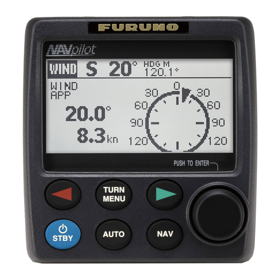
- Page 1 NAVpilot-700 NAVpilot-711 NAVpilot-720 NAVpilot-700 WIND NAVpilot-720 NAVpilot-711 www.furuno.co.jp...
- Page 2 *00017181213* *00017181213* *00017181213* *00017181213*...
-
Page 3: Important Notices
How to discard a used battery Some FURUNO products have a battery(ies). To see if your product has a battery, see the chapter on Maintenance. Follow the instructions below if a battery is used. Tape the + and - terminals of battery before disposal to prevent fire, heat generation caused by short circuit. -
Page 4: Safety Instructions
SAFETY INSTRUCTIONS Please read these safety instructions before you operate the equipment. WARNING Indicates a condition that can cause death or serious injury if not avoided. Indicates a condition that can cause minor or moderate injury if CAUTION not avoided. Warning, Caution Mandatory Action Prohibitive Action... -
Page 5: Table Of Contents
Control Unit FAP-7021 ...................1-2 1.2 How to Turn Power On, Off ..................1-3 1.3 How to Adjust Brilliance, Contrast ................1-4 1.3.1 NAVpilot-700 ....................1-4 1.3.2 NAVpilot-711, NAVpilot-720 ................1-4 1.4 Displays in the STBY, AUTO, NAV, WIND and Fish Hunter Modes ......1-5 1.4.1 Content of displays in the STBY, AUTO, NAV, WIND and FishHunter modes ..................1-5... - Page 6 TABLE OF CONTENTS 2.8 REMOTE Mode......................2-20 2.8.1 Dial-type remote controller (FAP-5551, FAP-5552) ........2-20 2.8.2 Button-type remote controller (FAP-6211, FAP-6212), Dodge-type remote controller (FAP-6231, FAP-6232), Lever-type remote controller (FAP-6221, FAP-6222)....................2-21 2.9 DODGE Mode ......................2-23 2.9.1 How to dodge in the AUTO and NAV modes ..........2-23 2.9.2 How to FU dodge in the STBY mode ............
- Page 7 TABLE OF CONTENTS MAINTENANCE, TROUBLESHOOTING ..............5-1 5.1 Preventive Maintenance .....................5-1 5.2 Replacement of Fuse ....................5-2 5.3 Diagnostics .........................5-2 5.3.1 Diagnostic menu.....................5-2 5.3.2 Processor unit test..................5-3 5.3.3 Control unit test ....................5-3 5.3.4 NMEA0183 test ....................5-4 5.3.5 CAN bus test ....................5-4 5.3.6 Keyboard test ....................5-5 5.3.7 Screen test .....................5-5...
-
Page 8: Foreword
FOREWORD A Word to the Owner of the NAVpilot-700/711/720 Congratulations on your choice of the NAVpilot-700/711/720. We are confident you will see why the FURUNO name has become synonymous with quality and reliability. For over 60 years FURUNO Electric Company has enjoyed an enviable reputation for innovative and dependable marine electronics equipment. -
Page 9: System Configuration
SYSTEM CONFIGURATION CONTROL UNIT FAP-7021 CONTROL UNIT CONTROL UNIT FAP-7001 FAP-7011 CONTROL UNIT QTY JUNCTION BOX FAP-7001/7011: MAX. 6* FAP-7822 FAP-7021: MAX. 2 Select one CONTACT SIGNAL IN SOLENOID VALVE SHIP'S CONTACT SIGNAL OUT STEERING HYDRAULIC LINEAR DRIVE SYSTEM PC (for serviceman) RUDDER REFERENCE UNIT FAP-6112 HEADING SENSOR... - Page 10 SYSTEM CONFIGURATION This page is intentionally left blank. viii...
-
Page 11: Introduction
The Control Unit for your NAVpilot is either the FAP-7001, FAP-7011, or FAP-7021. The descriptions in this manual mainly follow the key names of the NAVpilot-700 (Con- trol Unit FAP-7001). Refer to the table below for equivalent controls on the NAVpilot-711 and NAVpilot-720. -
Page 12: Control Unit Fap-7011
1. INTRODUCTION 1.1.2 Control Unit FAP-7011 STBD (STARBOARD) key Steer boat to starboard. PORT key Steer boat to port. Course control knob Rotate: Select menu items and POWER/STBY key options; set course on AUTO mode. Momentary press: Turn on power; go to STBY mode. Push: Confirm menu setting. -
Page 13: How To Turn Power On, Off
6454007-**.** NAVPILOT-700* CONTROLLER 6454011-**.** ROM RAM BACKUP PROCESSOR UNIT OK CONTROLLER FURUNO ELECTRIC CO., LTD HEADING SENSOR 359.9° * Or NAVPILOT-711, NAVPILOT-720 ------------------------------------------- P12.3° CONTROLLER ID 1 **.** : Program version no. If NG appears for any item, an error message, shown in the table below, appears. Fol- low the information provided in the message to restore normal operation. -
Page 14: How To Adjust Brilliance, Contrast
1. INTRODUCTION How to Adjust Brilliance, Contrast 1.3.1 NAVpilot-700 1. Short-push the POWER/BRILL key to show the screen for the adjustment of con- trast and brilliance. 2. Operate the Course control knob to adjust the contrast. (Contrast can also be ad- justed (cyclically) with the POWER/BRILL key.) -
Page 15: Displays In The Stby, Auto, Nav, Wind And Fish Hunter Modes
Displays in the STBY, AUTO, NAV, WIND and Fish Hunter Modes There are four (NAVpilot-700) or five (NAVpilot-711, NAVpilot-720) displays to select from in the STBY mode. To select a display, press the STBY key, AUTO key or NAV key continuously to step through the displays. - Page 16 1. INTRODUCTION NAVpilot-711, NAVpilot-720 • Autopilot Display 1 (Digital course and heading) • Autopilot Display 2 (Digital course and heading, and digital and analog rudder an- gle) • Nav Data Display 1 (Digital course and heading, digital and analog rudder angle, and one nav data display) •...
- Page 17 1. INTRODUCTION Available displays The table below shows all the nav data and graphic displays available. Appropriate sensors are required. Data displayed Data meaning Nav data displays AIR TEMP Air temperature ATMOS PRESS Atmospheric pressure Bearing to waypoint Course over ground DATE Current date DEWPOINT...
-
Page 18: Graphic Displays
1. INTRODUCTION 1.4.2 Graphic displays Compass rose, rudder display The compass rose and rudder display show ship’s heading in graphic form and rudder angle in both analog and digital formats. Requires heading data. Compass rose Rudder angle (port 19 ° Depth display The depth display provides depth data in a graph. -
Page 19: Engine Speed Display
1. INTRODUCTION Engine speed display The engine speed display shows the engine revolution. Requires engine speed data. 9: 9000 rpm Highway display The highway display provides a graphic presentation of your boat’s progress along its intended course. The own ship marker moves according to your boat’s track to the waypoint. - Page 20 1. INTRODUCTION Water temperature display The water temperature display shows water temperature over the selected time inter- val, and the current water temperature. Data scrolls across the screen from right to left. The interval of time can be selected from the menu. Requires water temperature data.
-
Page 21: How To Select The Data To Show In The Stby Mode
1. INTRODUCTION 1.4.3 How to select the data to show in the STBY mode You can select the data to show in the STBY mode as follows: 1. Short press the STBY key to go to the STBY mode. 2. Press the STBY key again to select a display. For example, select the nav data display. -
Page 22: How To Select Displays From The Menu
STBY, AUTO and NAV modes. STBY, AUTO, NAV[2]* STBY, AUTO, NAV[3]* STBY, AUTO, NAV[1]* STBY, AUTO, NAV[4]* Navpilot-700 1: RUDDER 1: RUDDER 1: POS 1: COMPASS 2: POS 2: COG... - Page 23 NAVPILOT-700: 1 of [1], [2] NAVPILOT-711, 720: 1 of [2], [3] RUDDER DEVIATION NAVPILOT-700: 2 of [2], 1 and 2 of [3] NAVPILOT-711, 720: 2 of [3], 1 and 2 of [4] AIR TEMP ATMOS PRESS HUMIDITY...
- Page 24 1. INTRODUCTION This page is intentionally left blank. 1-14...
-
Page 25: Steering Modes
Heading mode 323° T: True M: Magnetic Heading Data name (rudder) RUDDER 0° Rudder angle (digital) Rudder angle (analog) Autopilot display 1 (NAVpilot-700) Steering mode Heading mode HDG T T: True 323° M: Magnetic Data name (rudder) RUDDER Heading Rudder angle (digital) 0°... -
Page 26: Auto Modes
2. STEERING MODES AUTO Modes 2.2.1 AUTO mode The AUTO mode steers the boat automatically on a course set by the operator. The AUTO mode will not compensate for the effects of wind or tide, which can push you off course athwart in the ship direction. Use the AUTO mode for short, straight voyages. - Page 27 Heading mode 323° T: True M: Magnetic Heading Data name (rudder) RUDDER 0° Rudder angle (digital) Rudder angle (analog) Autopilot display 1 (NAVpilot-700) Steering mode: AUTO Set course Course mode T: True Heading mode 323° HDG T M: Magnetic SETCSE T: True 323°...
-
Page 28: Advanced Auto Mode
2. STEERING MODES 2.2.2 ADVANCED AUTO mode The AUTO mode keeps a set course, but your boat’s course can change by the effects of tide and wind. To adjust for the effects of tide and wind, use the ADVANCED AUTO mode. - Page 29 Heading mode 323° T: True M: Magnetic Heading Data name (rudder) RUDDER 0° Rudder angle (digital) Rudder angle (analog) Autopilot display 1 (NAVpilot-700) Steering mode: ADVANCED AUTO Set course Course mode T: True Heading mode 323° HDG T M: Magnetic SETCSE T: True 323°...
-
Page 30: Nav Mode
2. STEERING MODES NAV Mode NAVpilot steers the vessel towards the current waypoint while compensating for the effects of tide and wind. When connected to a GPS Navigator, NAVpilot steers the vessel to follow a series of waypoints in sequence. When you arrive at each waypoint or destination, audible and visual alerts are activated. - Page 31 T: True M: Magnetic Set course 323° Heading Data name (rudder) RUDDER 0° Rudder angle (digital) Rudder angle (analog) Autopilot display 1 (NAVpilot-700) Selected navigator Steering mode Waypoint name Set course Bearing SRC: NAVNET WPT: CRAB Heading mode 323° HDG T T: True 323°...
- Page 32 T: True M: Magnetic 323° Heading Data name (rudder) RUDDER 0° Rudder angle (digital) Rudder angle (analog) Autopilot display 1 (NAVpilot-700) Steering mode ECO: Economy Selected navigator XTE: Precision Waypoint name Cross-track error SRC: NAVNET WPT: CRAB Cross-track 0.01...
-
Page 33: Sailing Method For The Nav Mode
2. STEERING MODES 2.3.2 Sailing method for the NAV mode Your vessel can go off course between waypoints in the NAV mode. This can occur when, for example, a command is received from a remote controller. To return to the course set, three methods are available: [COURSE], [XTE (PRECISION], and [XTE (ECONOMY)]. -
Page 34: Waypoint Switching Method
2. STEERING MODES 2.3.3 Waypoint switching method When you arrive at a waypoint on a route in the NAV mode, you can switch to the next waypoint automatically or manually. The AUTO setting switches to the next destination waypoint when your boat is within the arrival alarm area (set on the chartplotter). -
Page 35: Response Feature
2. STEERING MODES Response Feature The Response feature provides for simple setting of the NAVpilot’s parameters. This is useful when you need a quick adjustment to counter the effects of wind, etc. This feature is available in the following conditions: •... -
Page 36: Turn Mode
How to select a turn and start the turn Select the 180°, 360°, or User turn as follows: 1. Press the TURN key to show the Turn menu. NAVpilot-700 NAVpilot-711/NAVpilot-720 2. Rotate the Course control knob to select a turn. The cursor highlights current se- lection. -
Page 37: 180° Turn
2. STEERING MODES 2.5.2 180° turn This function changes the current set course by 180° in the opposite direction. This feature is very useful in a man overboard situation and whenever you want to steer back on a reciprocal heading. 2.5.3 360°... -
Page 38: Fishhunter Mode
2. STEERING MODES FishHunter Mode The FishHunter mode is a unique feature of FURUNO’s NAVpilot series. Find a fish target with your FURUNO sonar/sounder or bird target with your FURUNO radar and feed it to the NAVpilot. The NAVpilot will activate the FishHunter mode to perform cir- cle, orbit, spiral, figure eight, square or zigzag maneuvers around the specified target. -
Page 39: How To Select A Fishhunter Turn And Start The Turn
Set at menu item DISTANCE. 2.6.2 How to select a FishHunter turn and start the turn 1. Press the TURN key to show the Turn menu. NAVpilot-700 NAVpilot-711/NAVpilot-720 2. Rotate the Course control knob to select a FishHunter turn. The cursor highlights current selection. -
Page 40: Circle Turn
2. STEERING MODES 180° TURN 360° TURN USER TURN CIRCLE TURN ORBIT TURN SPIRAL TURN FIGURE 8 SQUARE ZIGZAG TURN TURN TURN 3. If you want to change the parameters for the turn, do 1) - 3) below. If you do not need to change the parameters, push the Course control knob to start the turn. -
Page 41: Orbit Turn
2. STEERING MODES 2.6.4 Orbit turn In the AUTO mode, your boat orbits around its current position. For the NAV mode, the boat orbits around the (last) waypoint. This function requires a chartplotter or GPS navigator. Radius (set on menu) 2.6.5 Spiral turn The boat spirals in the direction of current heading (STBY), set course (AUTO) or the... -
Page 42: Figure-Eight Turn
2. STEERING MODES 2.6.6 Figure-eight turn After the boat has traveled the distance "d" set on the menu, it starts turning in a figure- eight pattern, automatically returning to the position where the figure-eight was initiat- ed. "d", the radius, is set on the menu. Radius set on menu 2.6.7 Square turn... -
Page 43: Zigzag Turn
2. STEERING MODES 2.6.8 Zigzag turn The zigzag turn starts from current position. The distance between legs, turn angle, number of turns and how to stop the zigzag turn can be set on the menu. This turn is available in the AUTO and NAV modes. 6th turn 7th turn 4th turn... -
Page 44: Remote Mode
2. STEERING MODES REMOTE Mode Four types of optional remote controllers can be connected to your NAVpilot to control the NAVpilot from a remote location. 2.8.1 Dial-type remote controller (FAP-5551, FAP-5552) These are FU-type remote controllers, and they can be used in the AUTO and NAV modes. -
Page 45: Button-Type Remote Controller (Fap-6211, Fap-6212), Dodge-Type Remote Controller (Fap-6231, Fap-6232), Lever-Type Remote Controller (Fap-6221, Fap-6222)
2. STEERING MODES Control is returned to the main control unit and the mode that was originally active (AUTO or NAV) is restored. For the NAV mode, the boat will go to the destination way- point based on the (COURSE or XTE) nav steering method menu setting. 2.8.2 Button-type remote controller (FAP-6211, FAP-6212), Dodge- type remote controller (FAP-6231, FAP-6232), Lever-type re-... - Page 46 Data name (rudder) RUDDER S2° Rudder angle (digital) Rudder angle (analog) Autopilot display in NFU mode (example: NAVpilot-700) 2. For button-and dodge-type remote controllers, press the key on the re- mote controller. For the lever-type, position the lever for the direction. 2-22...
-
Page 47: Dodge Mode
2. STEERING MODES 3. For the button-and lever-type remote controllers, turn off the remote controller to terminate the REMOTE mode. For the dodge-type remote controller, simply re- lease a key. Control is returned to the control unit and the previously used mode (STBY, AUTO or NAV). -
Page 48: How To Fu Dodge In The Stby Mode
Data name (rudder) RUDDER 0° Rudder angle (digital) Rudder angle (analog) Autopilot display (NAVpilot-700) 2.9.2 How to FU dodge in the STBY mode Press the key down to steer appropriately until the boat has cleared the ob- struction. The equipment goes into the DODGE mode (from STBY to DODGE mode the mode indication shows "NFU"* (Non-Follow Up) while pressing the... -
Page 49: Wind Mode (For Sailboats)
Wind angle indicator Wind angle (Triangle moves with wind.) Set wind angle (between heading 22.1°S and wind direction) 16° HDG T Heading mode 18° T: True M: Magnetic COMPASS Heading Compass rose Rudder RUDDER angle P1° Rudder angle (analog) NAVpilot-700 2-25... -
Page 50: Wind Angle Mode
2. STEERING MODES 2.10.2 Wind angle mode There are three wind angle modes: AWA (Apparent Wind Angle) and TWA (True Wind Angle). AWA: The boat is steered so that the apparent wind angle is constant. AWA mode re- quires wind angle and speed data from a wind sensor. Use this mode when wind is stable. -
Page 51: Tack Mode
SLOW TURN TO STBD SLOW TURN TO STBD NAVpilot-711NAVpilot-720 NAVpilot-700 3. Rotate the Course control knob to select a turn. SLOW TURN TO PORT or SLOW TURN TO STBD: For gybing, when the wind angle is larger than 120°. The boat slowly changes the heading angle. -
Page 52: Tacking In Wind Mode (Wind Tack)
2. STEERING MODES How to set the rate of turn for FAST and SLOW tacking The rate of turn is preset as 3° for SLOW and 20° for FAST. If you need to change the value, do the following: 1. Press the MENU key to open the menu. 2. - Page 53 2. STEERING MODES To start turning, do the following: 1. In the WIND mode, press the TURN key to show the Turn menu. The turning direction is determined according to the heading at the time the key is pressed, as shown below. Wind direction STBD PORT...
- Page 54 2. STEERING MODES 3. Push the Course control knob to start the turn. The boat starts turning toward the selected direction until the heading changes twice that set when the Course control knob was pressed. When the Course control knob is pressed, for example, at the P (port) 50°, the boat turns until the heading decreases 100°.
- Page 55 2. STEERING MODES How to set the damping interval for wind data You can set the damping interval for wind data to compensate for random fluctuation in wind data. The higher the setting the more “smooth” the data. However, a high damping interval causes delay in receiving wind data;...
-
Page 56: Safe Helm Mode
This prevents continued turning of the helm. The mode and course indications flash when the safe helm mode activates. Flashing 323° 323° RUDDER 0° 323° HDG T SETCSE 323° RUDDER 0° Autopilot display 1 (NAVpilot-700) Autopilot display 2 (NAVpilot-711, NAVpilot-720) 2-32... - Page 57 2. STEERING MODES How to set the safe helm mode 1. Open the menu in the STBY mode. 2. Use the Course control knob to select the [OTHER] menu then select [SAFE HELM/P.ASSIST SETUP]. SAFE HELM/P.ASSIST SETUP SAFE HELM: RETURN DELAY 5 SEC SAFE HELM RESPONSE POWER ASSIST: OFF 3.
-
Page 58: Power Assist Mode
SETCSE 323° RUDDER 0° Autopilot display 1 (NAVpilot-700) Autopilot display 2 (NAVpilot-711, NAVpilot-720) How to set the power assist mode 1. Open the menu in the STBY mode.. 2. Use the Course control knob to select the [OTHER] menu then select [SAFE HELM/P.ASSIST SETUP]. - Page 59 2. STEERING MODES 4. Use the Course control knob to select [ON] then push the knob. When this is done the menu items for power assist appear. SAFE HELM/P.ASSIST SETUP SAFE HELM: RETURN DELAY 5 SEC SAFE HELM RESPONSE POWER ASSIST: OFF FOR SPEEDS UNDER 3.0kn POWER ASSIST STBY: ON POWER ASSIST RUDDER SPEED...
- Page 60 2. STEERING MODES This page is intentionally left blank. 2-36...
-
Page 61: Alarms
ALARMS Your NAVpilot has nine conditions which generate both audio and visual alarms: watch alarm, deviation alarm, XTE (cross-track error) alarm, wind alarm (four types, sailboats only), arrival alarm, speed alarm, depth alarm, water temperature alarm, and log trip alarm. When an alarm is violated, the buzzer sounds, and the alarm icon ( ) and a pop-up message display appear (see section 5.5.3). -
Page 62: Alarm Buzzer
3. ALARMS Alarm Buzzer You can select the buzzer from which to output the audio alarm as follows. Use the external buzzer if the volume of the internal buzzer is not loud enough. 1. Rotate the Course control knob to select [BUZZER] from the ALARM menu then push the knob. -
Page 63: Watch Alarm
3. ALARMS Watch Alarm The watch alarm periodically warns the helmsman to check the NAVpilot when in the AUTO or NAV mode. 1. Rotate the Course control knob to select [WATCH ALARM] from the [ALARM] menu then push the knob. 2. -
Page 64: Xte Alarm
3. ALARMS XTE Alarm The XTE alarm, which is available in the NAV mode, alerts you when the course error has exceeded the XTE alarm setting. Own ship Destination Alarm position setting Intended course : Alarm 1. Rotate the Course control knob to select [XTE ALARM] from the [ALARM] menu then push the knob. -
Page 65: Arrival Alarm
3. ALARMS Arrival Alarm The arrival alarm alerts you when you are within a specific distance from a waypoint. Alarm range Own ship : Alarm area Waypoint 1. Rotate the Course control knob to select [ARRIVAL ALARM] from the [ALARM] menu then push the knob. -
Page 66: Depth Alarm
3. ALARMS Depth Alarm The depth alarm warns you when the bottom is shallower, deeper within or outside the depth alarm setting. Requires a depth sensor. 1. Rotate the Course control knob to select [DEPTH ALARM] from the [ALARM] menu then push the knob. SHALLOW DEEP INSIDE... -
Page 67: Trip Distance Alarm, Trip Distance Reset
3. ALARMS 3.11 Trip Distance Alarm, Trip Distance Reset 3.11.1 How to set the log trip alarm The log trip alarm alerts when you have traveled a specific distance. 1. Rotate the Course control knob to select [TRIP LOG] from the [ALARM] menu then push the knob. -
Page 68: Wind Alarms (For Sailboats)
3. ALARMS 3.12 Wind Alarms (for sailboats) The WIND alarm, which is an alarm exclusively for sailboats, has four conditions which generate both audio and visual alarms: heading change, wind deviation, true wind speed and apparent wind speed. To access the [WIND ALARM] menu, do the following: 1. -
Page 69: Wind Deviation Alarm
3. ALARMS 3.12.2 Wind deviation alarm The wind deviation alarm sounds when the current wind angle is greater than the wind angle limit set. 1. Rotate the Course control knob to select the value for [WIND DEVIATION ALARM] from the [WIND ALARM] menu then push the knob. 2. -
Page 70: Alarm Log
3. ALARMS 3.13 Alarm Log The Alarm Log shows the date, time and alarm no. of violated alarms. To show this log, select [ALARM LOG] from the [SYSTEM SETUP] menu. For a list of alarm num- bers, see section 5.5.3. ALARM LOG 2009/10/26 09:54:30 5105 Alarm no. -
Page 71: How To Customize Your Navpilot
SEA STATE: FULL-AUTO ADVANCED AUTO: MANUAL PARAMETER OTHER MENU NAVpilot-711/720 NAVpilot-700 Parameter Setup (PARAMETER SETUP Menu) The various parameters for your NAVpilot are set up from the [PARAMETER SETUP] menu, which is in the [OTHER MENU]. PARAMETER SETUP SEA STATE:... -
Page 72: Sea State
4. HOW TO CUSTOMIZE YOUR NAVPILOT 4.1.1 Sea state Your NAVpilot has an automatic adjustment feature which sets up the equipment ac- cording to ship's characteristics and sea state, for optimum performance in the AUTO, NAV and WIND modes. In addition, a self-learning algorithm is incorporated: Param- eters for rudder ratio, counter rudder and auto trim gains are constantly optimized based on the steering history of your boat, and are stored in memory for future navi- gation. - Page 73 4. HOW TO CUSTOMIZE YOUR NAVPILOT How to manually set NAVpilot steering parameters When [MANUAL-CALM], [MANUAL-MODERATE] or [MANUAL-ROUGH] is selected as the sea state, set [MANUAL PARAMETER] as below. You can set three parameters for the MANUAL function: Weather, Rudder gain and Counter rudder.
- Page 74 4. HOW TO CUSTOMIZE YOUR NAVPILOT [RUDDER GAIN]: When the boat's heading deviates from the set course, the NAVpilot adjusts the rudder to correct it. The rudder angle (number of degrees) which is steered against every degree of course deviation is known as the rudder gain. The following illustrations show how many degrees the NAVpilot steers the rudder in order to nullify 4 degrees of course deviation with various settings of the rudder gain.
-
Page 75: Trim Gain
4. HOW TO CUSTOMIZE YOUR NAVPILOT Large course error Intended Counter rudder: course small setting Counter rudder: proper setting The counter rudder feature functions to smoothly return ship's heading toward intended course. Slow Speed Fast Light Load Condition Heavy COUNTER RUDDER High 4.1.2 Trim gain... -
Page 76: Speed Calculation
4. HOW TO CUSTOMIZE YOUR NAVPILOT 4.1.3 Speed calculation Speed is normally entered automatically, from your navigator. If the navigator fails, manually enter speed. 1. Rotate the Course control knob to select [SPEED CALCULATION] from the [PA- RAMETER SETUP] menu. 2. -
Page 77: Course After Operation Of A Remote Controller
4. HOW TO CUSTOMIZE YOUR NAVPILOT Course After Operation of a Remote Controller Select the course to follow after a remote controller is operated. Previous course Previous course New course Remote Remote controller: OFF Remote controller: OFF controller: ON Remote controller: ON PRESENT COURSE mode PREVIOUS COURSE mode... -
Page 78: Navnet Vx2 Synchronization
4. HOW TO CUSTOMIZE YOUR NAVPILOT 5. Rotate the Course control knob to select [SOURCE1] then push the knob. - - - - - - - - - - - - - - NAVNET3: 000C2F PORT2 If you have some equipment which outputs nav data, the name appears in the win- dow. -
Page 79: System Setup Menu
PASSWORD: 0000 DISPLAY DATA SELECT MENU PASSWORD FUNCTION: OFF RECEIVE SCREEN: OFF Page 3 SYSTEM SETUP SYSTEM DATA SYSTEM SETUP menu (shown: NAVpilot-700) SYSTEM SETUP menu description Item Description Options [KEY BEEP] Turn the key beep on or off. [ON], [OFF]... - Page 80 4. HOW TO CUSTOMIZE YOUR NAVPILOT Item Description Options [PASSWORD Activates or deactivates pass- [ON], [OFF] FUNCTION] word requirement. Select ON to require a password to access menus. If the password is entered correctly, the menu becomes op- erative and the option setting for this item changes to OFF.
-
Page 81: Menu Shortcuts
4. HOW TO CUSTOMIZE YOUR NAVPILOT Menu Shortcuts You can create menu shortcuts to the STBY mode menu for menu items which you often use. Up to 20 shortcuts can be created. 4.7.1 How to create a menu shortcut The procedure below shows you how to create a menu shortcut for the arrival alarm. 1. - Page 82 4. HOW TO CUSTOMIZE YOUR NAVPILOT This page is intentionally left blank. 4-12...
-
Page 83: Maintenance, Troubleshooting
MAINTENANCE, TROUBLESHOOTING This chapter provides the maintenance and troubleshooting procedures. NOTICE WARNING o not apply paint, anti-corrosive ELECTRICAL SHOCK HAZARD Do not open the equipment. sealant or contact spray to plastic parts or equipment coating. This equipment uses high voltage that can cause Those items contain products that can electrical shock. -
Page 84: Replacement Of Fuse
5. MAINTENANCE, TROUBLESHOOTING Replacement of Fuse Two fuses (125V 4A) in the processor unit protect the equipment from reverse polarity of the ship's mains and equipment fault. If a fuse blows, you cannot turn on the power. Have a qualified technician check the set. WARNING Use the proper fuse. -
Page 85: Processor Unit Test
5. MAINTENANCE, TROUBLESHOOTING 5.3.2 Processor unit test This test checks the processor unit for correct operation. Open the diagnostic test op- tions window, select [PROCESSOR UNIT] then push the Course control knob. The results for the ROM, RAM and RUDDER ANGLE are shown as OK or NG. If NG ap- pears, repeat the test. -
Page 86: Nmea0183 Test
5. MAINTENANCE, TROUBLESHOOTING 5.3.4 NMEA0183 test This test checks for correct input and output of NMEA 0183 data from PORT1 and PORT2. The test is for service technicians and requires a special test connector. (If the test is done without the connector, the results are shown as “- -”.) Open the diagnostic test options window, select [NMEA0183 TEST] then push the Course control knob. -
Page 87: Keyboard Test
TO RETURN NAVpilot-711/720 PUSH MENU KEY THREE TIMES TO RETURN NAVpilot-700 5.3.7 Screen test The screen test checks the control unit for correct presentation of black and white tones. Open the diagnostic test options window, select [SCREEN TEST] then push the Course control knob. -
Page 88: Rudder Test
5. MAINTENANCE, TROUBLESHOOTING 5.3.8 Rudder test The rudder test checks drive type, presence or absence of bypass/clutch circuit, rud- der deadband, rudder speed, rudder duty*, and rudder angle. Open the diagnostic test options window, select [RUDDER TEST] then push the Course control knob. You are asked to center the rudder. -
Page 89: System Data
5. MAINTENANCE, TROUBLESHOOTING System Data The system data display allows you to confirm the equipment and drive system status. To show this display, open the [SYSTEM MENU], select [SYSTEM DATA] then push the Course control knob. INPUT VOLTAGE: 24.4 V CONTROLLER ID: 2 DRIVE TYPE: REVERSIBLE 24V BYPASS/CLUTCH: NOT PRESENT... -
Page 90: Messages
5. MAINTENANCE, TROUBLESHOOTING Messages Your equipment displays messages to alert you to potential equipment problem and operation status. 5.5.1 Message pop-up display When the system detects alarm violation, error, etc., the buzzer sounds and an error message pop-up display appears. The illustration below shows the message for rud- der drive error. - Page 91 5. MAINTENANCE, TROUBLESHOOTING Error Error message Meaning, remedy 5305 "APP WIND SPEED ALARM" Apparent wind alarm violated (sailboats only). 5307 "SPEED ALARM" Speed alarm violated. 5309 "WATER TEMP ALARM" Water temperature alarm violated. 5311 "DEPTH ALARM" Depth alarm violated. 5313 "TRIP ALARM"...
- Page 92 5. MAINTENANCE, TROUBLESHOOTING Error Error message Meaning, remedy 0011 "BYPASS/CLUTCH IS SHORT- Bypass/clutch is shorted. Turn off power. ED OUT" 0013 "RUDDER DRIVE ERROR" Turn off power. 0017 "RUDDER ANGLE ERROR" Turn off power. 0301 "COMMUNICATION ERROR" No communication between processor unit and all control units.
-
Page 93: Sensor In Use Display
The display shows the source for each data and the equipment identifier number. For example the source of HDG is the FURUNO PG-700 and its equipment identifier num- ber is 0019E4. Dashed lines indicate no connection or sensor is not currently active. - Page 94 5. MAINTENANCE, TROUBLESHOOTING This page is intentionally left blank. 5-12...
-
Page 95: Appendix 1 Menu Tree
APPENDIX 1 MENU TREE STBY mode menu [MENU] key MESSAGE SENSOR IN USE CONTRAST/BRILLIANCE (1-16, 8 / 1-8, 8) (1-8=NAVPilot-711/720) SEA STATE See AUTO/NAV menu on page AP-3. MANUAL PARAMETER ADVANCED AUTO Bold Italic: Default WIND DAMPING* (0.7-99.9 sec, 5.0 sec) OTHER ALARM BUZZER (INTERNAL, INTERNAL +EXTERNAL) - Page 96 APPENDIX 1 MENU TREE (Continued from previous page) FISH CIRCLE (RATE OF TURN* 1° to 5°, 3°) HUNTER ORBIT (RADIUS, 0.05-9.99nm, 0.05nm) OPTION* SPIRAL (SPEED, 0.1-2.0kn, 0.5kn) RADIUS (0.05-9.99nm, 0.05nm) FIGURE 8 (RADIUS, 0.05-9.99nm, 0.05nm)) SQUARE TURN (SIDE LENGTH, 1.0-9.9nm, 1.0nm; AZIMUTH (AUTO, MANUAL, 0°-359°, 0°) ZIGZAG TURN ANGLE (30°-150°, 90°)
- Page 97 NMEA0183 TEST, CAN BUS TEST, KEYBOARD TEST, SCREEN TEST, RUDDER TEST, HELM TEST) DISPLAY DATA SELECT MENU STBY See the next page for available AUTO SYSTEM DATA display division and data WIND* NAVpilot-700 only *2 [SHIP’S CHARACTERISTICS]=other than sailboat AP-3...
- Page 98 (SMALL, LARGE) ARROW KEY (DODGE, 5°, 10°, MANUAL(1°-90°, 20°)) DISPLAY DATA SELECT MENU SYSTEM DATA NAVpilot-711, 720 [SHIP’S CHARACTERISTICS]=sailboat NAVpilot-700 Note: WIND display also available when [SHIP’S CHARACTERISTICS]=sailboat STBY, AUTO, NAV[2] STBY, AUTO, NAV[3] STBY, AUTO, NAV[1] STBY, AUTO, NAV[4]...
-
Page 99: Specifications
SPECIFICATIONS OF AUTOPILOT NAVpilot-700/711/720 CONTROL UNIT Display Monochrome dot matrix LCD Effective display area NAVpilot-700: 85.2 (W) x 85.2 (H) mm (160 x 160 dot) NAVpilot-711/720: 85.2 (W) x 43.6 (H) mm (160 x 80 dots) Backlight 8 steps Contrast 16 steps... - Page 100 FURUNO NAVpilot-700/711/720 CAN bus PGN (NMEA2000) Input 059392, 059904, 060928, 061184, 126208, 126464, 126720, 126992, 126996, 127250, 127251, 127258, 127488, 127489, 128259, 128267, 129025, 129026, 129029, 129033, 129283, 129284, 129285, 130306, 130310, 130311, 130312, 130313, 130314, 130577, 130880 3.4 Output...
-
Page 101: Index
..... 3-9 Display data in AUTO mode... 1-12 4-10 arrival alarm ..........3-5 Display mode buzzer ............. 3-2 NAVpilot-700 ........... 1-5 buzzer interval ......... 3-2 NAVpilot-711/720 ........1-6 depth alarm ..........3-6 Display settings saving, loading ....4-10 deviation ..........3-3 DODGE mode heading change alarm...... - Page 102 Weather setting ..........4-3 Parameter setup menu ......4-1 Wind deviation alarm........3-9 Password ...........4-9 Wind display..........1-10 Power assist mode........2-34 WIND mode POWER/BRILL key (NAVpilot-700) ...1-3 starting ...........2-25 Processor unit test ........5-3 wind angle ..........2-26 REMOTE mode........2-20 Response ..........2-11 XTE alarm ..........3-4 Rudder display ...........1-9 Rudder gain setting ........4-3...