Draytek Vigor 2110 User Manual
Vigor 2110 series broadband firewall router
Hide thumbs
Also See for Vigor 2110:
- Specifications (2 pages) ,
- Declaration of conformity (1 page) ,
- User manual (226 pages)
Table of Contents
Advertisement
Advertisement
Table of Contents

Related Manuals for Draytek Vigor 2110


Summary of Contents for Draytek Vigor 2110
- Page 2 Vigor2110 Series Broadband Firewall Router User’s Guide Version: 3.2 Firmware Version: V3.6.3 Date: 06/03/2013 Vigor2110 Series User’s Guide...
-
Page 3: Copyright Information
Copyright Information Copyright 2013 All rights reserved. This publication contains information that is Copyright protected by copyright. No part may be reproduced, transmitted, transcribed, stored in a Declarations retrieval system, or translated into any language without written permission from the copyright holders. -
Page 4: European Community Declarations
European Community Declarations Manufacturer: DrayTek Corp. Address: No. 26, Fu Shing Road, HuKou Township, HsinChu Industrial Park, Hsin-Chu, Taiwan 303 Product: Vigor2110 Series Router DrayTek Corp. declares that Vigor2110 Series of routers are in compliance with the following essential requirements and other relevant provisions of R&TTE Directive 1999/5/EEC. The product conforms to the requirements of Electro-Magnetic Compatibility (EMC) Directive 2004/108/EC by complying with the requirements set forth in EN55022/Class B and EN55024/Class B. -
Page 5: Table Of Contents
Introduction ....................1 1.1 Web Configuration Buttons Explanation ................. 1 1.2 LED Indicators and Connectors ....................2 1.2.1 For Vigor2110 ........................2 1.2.2 For Vigor2110n ......................... 4 1.2.3 For Vigor2110Vn....................... 6 1.3 Hardware Installation ......................8 Stand Installation ........................9 1.4 Printer Installation ......................... 10 Initial Configuration ...................15 2.1 Accessing the Web User Interface.................. - Page 6 3.7.2 Peer-to-Peer Calling ....................... 66 3.8 Request a certificate from a CA server on Windows CA Server ........... 67 3.9 Request a CA Certificate and Set as Trusted on Windows CA Server ......... 71 3.10 Creating an Account for MyVigor ..................73 3.10.1 Creating an Account via Vigor Router ................
- Page 7 4.7.3 Quality of Service......................175 4.7.4 APP QoS ........................184 4.8 Applications ......................... 185 4.8.1 Dynamic DNS ....................... 185 4.8.2 Schedule ........................188 4.8.3 RADIUS ........................190 4.8.4 UPnP..........................191 4.8.5 IGMP..........................193 4.8.6 Wake on LAN........................ 194 4.9 VPN and Remote Access....................195 4.9.1 Remote Access Control ....................
- Page 8 4.14.11 Firmware Upgrade ....................282 4.14.12 Activation ........................283 4.15 Diagnostics........................284 4.15.1 Dial-out Triggering ...................... 284 4.15.2 Routing Table ......................285 4.15.3 ARP Cache Table ....................... 286 4.15.4 IPv6 Neighbour Table ....................286 4.15.5 DHCP Table........................ 287 4.15.6 NAT Sessions Table ....................288 4.15.7 Data Flow Monitor.......................
-
Page 9: Introduction
Vigor2110 series is a broadband router. It integrates IP layer QoS, NAT session/bandwidth management to help users control works well with large bandwidth. By adopting hardware-based VPN platform and hardware encryption of AES/DES/3DS, the router increases the performance of VPN greatly, and offers several protocols (such as IPSec/PPTP/L2TP) with up to 2 VPN tunnels. -
Page 10: Led Indicators And Connectors
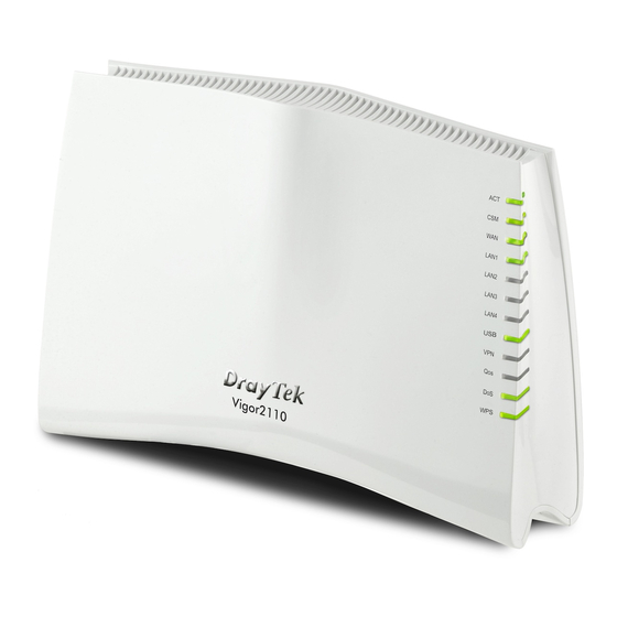
Before you use the Vigor router, please get acquainted with the LED indicators and connectors first. Status Explanation Blinking The router is powered on and running (Activity) normally. The router is powered off. The profile(s) of CSM (Content Security Management) for IM/P2P, URL/Web Content Filter application can be enabled from Firewall >>General Setup. - Page 11 Interface Description Factory Reset Restore the default settings. Usage: Turn on the router (ACT LED is blinking). Press the hole and keep for more than 5 seconds. When you see the ACT LED begins to blink rapidly than usual, release the button. Then the router will restart with the factory default configuration.
-
Page 12: For Vigor2110N
Status Explanation Blinking The router is powered on and running (Activity) normally. The router is powered off. WLAN Wireless access point is ready. Blinking It will blink while wireless traffic goes through. The WAN port is connected. Blinking It will blink while transmitting data. The port is connected. - Page 13 Interface Description Factory Reset Restore the default settings. Usage: Turn on the router (ACT LED is blinking). Press the hole and keep for more than 5 seconds. When you see the ACT LED begins to blink rapidly than usual, release the button. Then the router will restart with the factory default configuration.
-
Page 14: For Vigor2110Vn
Status Explanation Blinking The router is powered on and running (Activity) normally. The router is powered off. WLAN Wireless access point is ready. Blinking It will blink while wireless traffic goes through. The WAN port is connected. Blinking It will blink while transmitting data. The port is connected. - Page 15 Interface Description Line Connector for PSTN life line. Phone2/Phone1 Connecter of analog phone for VoIP communication Factory Reset Restore the default settings. Usage: Turn on the router (ACT LED is blinking). Press the hole and keep for more than 5 seconds. When you see the ACT LED begins to blink rapidly than usual, release the button.
-
Page 16: Hardware Installation
Before starting to configure the router, you have to connect your devices correctly. Connect Line port to land line jack with a RJ-11 cable (Vn model). Connect this device to a modem with a RJ-45 cable. Connect one port of 4-port switch to your computer with a RJ-45 cable. This device allows you to connect 4 PCs directly. -
Page 17: Stand Installation
The Vigor2110 must be placed erectly. Therefore you have to install a stand onto the router to make it standing firmly. Please follow the figures listed below to finish the installation. Vigor2110 Series User’s Guide... -
Page 18: Printer Installation
You can install a printer onto the router for sharing printing. All the PCs connected this router can print documents via the router. The example provided here is made based on Windows XP/2000. For Windows 98/SE/Vista, please visit www.draytek.com. Before using it, please follow the steps below to configure settings for connected computers (or wireless clients). - Page 19 Open File->Add Printer. A welcome dialog will appear. Please click Next. Click Local printer attached to this computer and click Next. In this dialog, choose Create a new port Type of port and use the drop down list to select Standard TCP/IP Port. Click Next. Vigor2110 Series User’s Guide...
- Page 20 In the following dialog, type 192.168.1.1 (router’s LAN IP) in the field of Printer Name or IP Address and type IP_192.168.1.1 as the port name. Then, click Next. Click Standard and choose Generic Network Card. Then, in the following dialog, click Finish. Vigor2110 Series User’s Guide...
- Page 21 Now, your system will ask you to choose right name of the printer that you installed onto the router. Such step can make correct driver loaded onto your PC. When you finish the selection, click Next. For the final stage, you need to go back to Control Panel-> Printers and edit the property of the new printer you have added.
- Page 22 The printer can be used for printing now. Most of the printers with different manufacturers are compatible with vigor router. Note 1: Some printers with the fax/scanning or other additional functions are not supported. If you do not know whether your printer is supported or not, please visit www.draytek.com to find out the printer list.
-
Page 23: Initial Configuration
For using the router properly, it is necessary for you to change the password of web configuration for security and adjust primary basic settings. This chapter explains how to setup a password for accessing into the web configurator of Vigor router and how to adjust settings for accessing Internet successfully. Make sure your PC connects to the router correctly. - Page 24 Now, the Main Screen will appear. Note: The home page will be different slightly in accordance with the type of the router you have. The web page can be logged out according to the chosen condition. The default setting is Auto Logout, which means the web configuration system will logout after 5 minutes without any operation.
-
Page 25: Changing Password
Please change the password for the original security of the router. Open a web browser on your PC and type http://192.168.1.1. A pop-up window will open to ask for username and password. Please type “admin/admin” as the Username/Password and click Login. Go to System Maintenance page and choose Administrator Password. -
Page 26: Quick Start Wizard
If your router can be under an environment with high speed NAT, the configuration provide here can help you to deploy and use the router quickly. The first screen of Quick Start Wizard is entering login password. After typing the password, please click Next. On the next page as shown below, please select the appropriate Internet access type according to the information from your ISP. -
Page 27: Pppoe
PPPoE stands for Point-to-Point Protocol over Ethernet. It relies on two widely accepted standards: PPP and Ethernet. It connects users through an Ethernet to the Internet with a common broadband medium, such as a single DSL line, wireless device or cable modem. All the users over the Ethernet can share a common connection. -
Page 28: Pptp/L2Tp
Retype the password. Confirm Password Click it to return to previous setting page. Back Click it to get into the next setting page. Next Click it to give up the quick start wizard. Cancel Type in all the information that your ISP provides for this protocol. Click Next for viewing summary of such connection. - Page 29 The following page will be shown. Available settings are explained as follows: Item Description Assign a specific valid user name provided by the ISP. User Name Assign a valid password provided by the ISP. Password Retype the password. Confirm Password Obtain an IP address automatically –...
-
Page 30: Static Ip
Click Next for viewing summary of such connection. Click Finish. Then, the system status of this protocol will be shown. Now, you can enjoy surfing on the Internet. Click Static IP as the protocol and click Next. Vigor2110 Series User’s Guide... - Page 31 The following page will be shown. Available settings are explained as follows: Item Description Type the IP address. WAN IP Type the subnet mask. Subnet Mask Type the IP address of gateway. Gateway Type in the primary IP address for the router. Primary DNS Type in secondary IP address for necessity in the future.
-
Page 32: Dhcp
Click Finish. Then, the system status of this protocol will be shown. Now, you can enjoy surfing on the Internet. Click DHCP as the protocol and click Next. The following page will be shown. Available settings are explained as follows: Item Description Type the name of the host. -
Page 33: Service Activation Wizard
Click it to give up the quick start wizard. Cancel Type in all the information that your ISP provides for this protocol. Click Next for viewing summary of such connection. Click Finish. Then, the system status of this protocol will be shown. Now, you can enjoy surfing on the Internet. - Page 34 The screen of Service Activation Wizard will be shown as follows. Choose the one you need and click Next. In this case, we choose to activate free trail edition. Free trial edition: it offers a period of trial for you to get acquainted with WCF function. Formal edition with license key: you can extend the license valid time manually.
- Page 35 Setting confirmation page will be displayed as follows, please click Next. Wait for a moment till the following page appears. When such page appears, you can enable or disable these services for your necessity. Then, click Finish. Note: The service will be activated and applied as the default rule configured in Firewall>>General Setup.
-
Page 36: Voip Wizard
Later, if you need to extend the license valid time, you can also use the Service Activation Wizard again to reach your goal by clicking the radio button of Formal edition with license key and clicking Next. Check the box of “I have read and accept the above..” and click Next. Follow the on-screen instruction to install the formal edition of WCF license. - Page 37 2. The screen of VoIP Wizard will be shown as follows. Available settings are explained as follows: Item Description VoIP service provider - Use the drop down list to choose Set VoIP service the ISP which offers the VoIP service for your router. If provider domain your ISP is not in the list, simply type the name of the ISP in the entry box.
-
Page 38: Online Status
4. Click Finish. A page of VoIP Wizard Setup OK!!! will appear. The online status shows the system status, WAN status, and other status related to this router within one page. If you select PPPoE/PPPoA as the protocol, you will find out a link of Dial PPPoE or Drop PPPoE in the Online Status web page. -
Page 39: Saving Configuration
Item Description WAN interface. TX Rate - Display the speed of transmitted octets at the WAN interface. RX Packets - Display the total number of received packets at the WAN interface. RX Rate - Display the speed of received octets at the WAN interface. -
Page 40: Registering Vigor Router
You have finished the configuration of Quick Start Wizard and you can surf the Internet at any time. Now it is the time to register your Vigor router to MyVigor website for getting more service. Please follow the steps below to finish the router registration. Please login the web configuration interface of Vigor router by typing “admin/admin”... - Page 41 A Login page will be shown on the screen. Please type the account and password that you created previously. And click Login. If not, please refer to section 4.13 Creating an Account for MyVigor. The following page will be displayed after you logging in MyVigor. From this page, please click Add or Product Registration.
- Page 42 When the following page appears, please type in Nickname (for the router) and choose the right registration date from the popup calendar (it appears when you click on the box of Registration Date). After adding the basic information for the router, please click Submit.
-
Page 43: Application And Example
Due to the shortage of IPv4 address, more and more countries use IPv6 to solve the problem. However, to continually use the original rich resources of IPv4, both IPv6 and IPv4 networks shall communicate for each other via intercommunication mechanism to complete the shifting job from IPv4 to IPv6 gradually. - Page 44 In the following figure, use the drop down list to choose a proper connection type. Different connection types will bring out different configuration page. Refer to the following: PPP – Dual Stack application, IPv4 and IPv6 services can be utilized at the same time Choose PPP and type the information for PPPoE of IPv4.
- Page 45 Access into the setting page for IPv6 service, it is not necessary for you to configure anything. Click OK and open Online Status. If the connection is successful, you will get the IP address for IPv4 and IPv6 at the same time. Vigor2110 Series User’s Guide...
- Page 46 TSPC – Tunnel application, both IPv6 hosts communicate through IPv4 network Choose TSPC and type the information for TSPC service. Note: While using such mode, you have to make sure the IPv4 network connection is normal. (In the following figure, the TSPC information is obtained from http://gogo6.com/ after applied for the service.) Click OK and open Online Status.
- Page 47 AICCU – Tunnel application Choose AICCU and type the information for AICCU of IPv6. Note: While using such mode, you have to make sure the IPv4 network connection is normal. (In the following figure, the AICCU information is obtained from https://www.sixxs.net/main/ after applied for the service.) Click OK and open Online Status.
- Page 48 DHCPv6 Client Choose DHCPv6 Client. Click one of the identity associations and type the IAID number. Click OK and open Online Status. If the connection is successful, the physical connection will be shows as follows: Vigor2110 Series User’s Guide...
- Page 49 Static IPv6 Choose Static IPv6. Type IPv6 address, Prefix Length and Gateway Address. Click OK and open Online Status. If the connection is successful, the physical connection will be shows as follows: Vigor2110 Series User’s Guide...
- Page 50 After finished the WAN settings for IPv6, please configure the LAN settings to make the router’s client getting the IPv6 address. Access into the web configurator of Vigor2110. Open LAN>> General Setup. Click the IPv6 button. Note: Only the subnet of LAN1 supports IPv6 feature. In the field of RADVD Configuration, the default setting is Enable.
- Page 51 Make sure you have obtained the correct IPv6 IP address. Get into MS-DOS interface and type the command of “ipconfig”. Refer to the following figure. From the above figure we can see IPv6 IP address has been detected by the system. Use the Ping command to ping any IPv6 address indicating an IPv6 website.
- Page 52 Connect to the website for IPv6. Open a web browser and type an URL of IPv6, e.g., www.kame.net. If your computer accesses into the website by using IPv6 address, you may see a turtle dancing on the screen. If not, only a steady turtle will be seen. If you can see a turtle dancing on the screen, that means IPv6 service is ready for you to access and utilize.
-
Page 53: How Can I Use Ftp To Get The Files From Usb Storage Device Connecting To Vigor Router
There are three methods to get files from USB devices connecting to router. File Explorer – Under Administration operation, the administer can control the files on USB storage device through USB Application>>File Explorer. FTP – Use common FTP utility. Samba – Invoke Samba service and use \\192.168.1.1 to access into the USB storage device. - Page 54 Click OK to save the configuration. Make sure the FTP service is running properly. Please open a browser and type ftp://192.168.1.1. Use the account "user1" to login. When the following screen appears, it means the FTP service is running properly. Vigor2110 Series User’s Guide...
- Page 55 Return to USB Application >> USB Disk Status. The information for FTP server will be shown as below. Now, users in LAN of Vigor2110 can access into the USB storage device by typing ftp://192.168.1.1 on any browser. They can add or remove files / directories, depending on the Access Rule for FTP account settings in USB Application >>USB User Management.
-
Page 56: How To Customize Your Login Page
Login page can be customized to fit the request of the administrator. Open System Maintenance>>Login Page Greeting. Check the box, Enable to enable this function. Type a brief description (e.g., Just for Carrie) in the field of Login Page Title which will be shown on the heading of the login dialog. Type any message or description in the field of Welcome Message and Bulletin which will be shown on the bottom of the login dialog. - Page 57 After typing the username and password (defined in User Management>>User Profile), click Login. You can access into Internet or access into the Landing Page if configured in User Management>>General Setup. Vigor2110 Series User’s Guide...
-
Page 58: Create A Lan-To-Lan Connection Between Remote Office And Headquarter
The most common case is that you may want to connect to network securely, such as the remote branch office and headquarter. According to the network structure as shown in the below illustration, you may follow the steps to create a LAN-to-LAN profile. These two networks (LANs) should NOT have the same network address. - Page 59 For using IPSec-based service, such as IPSec or L2TP with IPSec Policy, you have to set general settings in IPSec General Setup, such as the pre-shared key that both parties have known. Go to LAN-to-LAN. Click on one index number to edit a profile. Set Common Settings as shown below.
- Page 60 Set Dial-Out Settings as shown below to dial to connect to Router B aggressively with the selected Dial-Out method. If an IPSec-based service is selected, you should further specify the remote peer IP Address, IKE Authentication Method and IPSec Security Method for this Dial-Out connection.
- Page 61 connection. Otherwise, it will apply the settings defined in IPSec General Setup above. If a PPP-based service is selected, you should further specify the remote peer IP Address, Username, Password, and VJ Compression for this Dial-In connection. At last, set the remote network IP/subnet in TCP/IP Network Settings so that Router A can direct the packets destined to the remote network to Router B via the VPN connection.
- Page 62 Settings in Router B in the remote office: Go to VPN and Remote Access and select Remote Access Control to enable the necessary VPN service and click OK. Then, for using PPP based services, such as PPTP, L2TP, you have to set general settings in PPP General Setup.
- Page 63 Set Dial-Out Settings as shown below to dial to connect to Router B aggressively with the selected Dial-Out method. If an IPSec-based service is selected, you should further specify the remote peer IP Address, IKE Authentication Method and IPSec Security Method for this Dial-Out connection.
- Page 64 connection. Otherwise, it will apply the settings defined in IPSec General Setup above. If a PPP-based service is selected, you should further specify the remote peer IP Address, Username, Password, and VJ Compression for this Dial-In connection. At last, set the remote network IP/subnet in TCP/IP Network Settings so that Router B can direct the packets destined to the remote network to Router A via the VPN connection.
-
Page 65: Create A Remote Dial-In User Connection Between The Teleworker And Headquarter
The other common case is that you, as a teleworker, may want to connect to the enterprise network securely. According to the network structure as shown in the below illustration, you may follow the steps to create a Remote User Profile and install Smart VPN Client on the remote host. - Page 66 For using IPSec-based service, such as IPSec or L2TP with IPSec Policy, you have to set general settings in IKE/IPSec General Setup, such as the pre-shared key that both parties have known. Go to Remote Dial-In User. Click on one index number to edit a profile. Set Dial-In settings to as shown below to allow the remote user dial-in to build VPN connection.
- Page 67 If a PPP-based service is selected, you should further specify the remote peer IP Address, Username, Password, and VJ Compression for this Dial-In connection. Settings in the remote host: For Win98/ME, you may use "Dial-up Networking" to create the PPTP tunnel to Vigor router.
- Page 68 In Step 2. Connect to VPN Server, click Insert button to add a new entry. If an IPSec-based service is selected as shown below, You may further specify the method you use to get IP, the security method, and authentication method. If the Pre-Shared Key is selected, it should be consistent with the one set in VPN router.
- Page 69 then forwarded to Internet. This will make the remote host seem to be working in the enterprise network. Click Connect button to build connection. When the connection is successful, you will find a green light on the right down corner. Vigor2110 Series User’s Guide...
-
Page 70: Lan - Created By Using Nat
– – An example of default setting and the corresponding deployment are shown below. The default Vigor router private IP address/Subnet Mask is 192.168.1.1/255.255.255.0. The built-in DHCP server is enabled so it assigns every local NATed host an IP address of 192.168.1.x starting from 192.168.1.10. - Page 71 You can just set the settings wrapped inside the red rectangles to fit the request of NAT usage. Vigor2110 Series User’s Guide...
-
Page 72: Calling Scenario For Voip Function
Example 1: Both John and David have SIP Addresses from different service providers. John’s SIP URL: 1234@draytel.org, David’s SIP URL: 4321@iptel.org Settings for John DialPlan index 1 Phone Number: 1111 Display Name: David SIP URL: 4321@iptel.org SIP Accounts Settings --- Profile Name: draytel1 Register via: Auto SIP Port: 5060 (default) - Page 73 (Use default value) Phone Number for John) Example 2: Both John and David have SIP Addresses from the same service provider. John’s SIP URL: 1234@draytel.org , David’s SIP URL: 4321@draytel.org Settings for John DialPlan index 1 Phone Number: 1111 Display Name: David SIP URL: 4321@draytel.org SIP Accounts Settings --- Profile Name: draytel 1...
-
Page 74: Peer-To-Peer Calling
Example 3: Arnor and Paulin have Vigor routers respectively. They can call each other without SIP Registrar. First they must have each other’s IP address and assign an Account Name for the port used for calling. Arnor’s SIP URL: 1234@214.61.172.53 Paulin’s SIP URL: 4321@ 203.69.175.24 Settings for Arnor DialPlan index 1... -
Page 75: Request A Certificate From A Ca Server On Windows Ca Server
Go to Certificate Management and choose Local Certificate. Vigor2110 Series User’s Guide... - Page 76 You can click GENERATE button to start to edit a certificate request. Enter the information in the certificate request. Copy and save the X509 Local Certificate Requet as a text file and save it for later use. Connect to CA server via web browser. Follow the instruction to submit the request. Below we take a Windows 2000 CA server for example.
- Page 77 Select Advanced request. Select Submit a certificate request a base64 encoded PKCS #10 file or a renewal request using a base64 encoded PKCS #7 file Import the X509 Local Certificate Requet text file. Select Router (Offline request) or IPSec (Offline request) below. Then you have done the request and the server now issues you a certificate.
- Page 78 you will find the below window showing “------BEGINE CERTIFICATE------..” You may review the detail information of the certificate by clicking View button. Vigor2110 Series User’s Guide...
-
Page 79: Request A Ca Certificate And Set As Trusted On Windows Ca Server
Use web browser connecting to the CA server that you would like to retrieve its CA certificate. Click Retrive the CA certificate or certificate recoring list. Vigor2110 Series User’s Guide... - Page 80 In Choose file to download, click CA Certificate Current and Base 64 encoded, and Download CA certificate to save the .cer. file. Back to Vigor router, go to Trusted CA Certificate. Click IMPORT button and browse the file to import the certificate (.cer file) into Vigor router. When finished, click refresh and you will find the below illustration.
-
Page 81: Creating An Account For Myvigor
The website of MyVigor (a server located on http://myvigor.draytek.com) provides several useful services (such as Anti-Spam, Web Content Filter, Anti-Intrusion, and etc.) to filtering the web pages for the sake of protecting your system. To access into MyVigor for getting more information, please create an account for MyVigor. 1. - Page 82 3. Click the link of Create an account now. 4. Check to confirm that you accept the Agreement and click Accept. 5. Type your personal information in this page and then click Continue. 6. Choose proper selection for your computer and click Continue. Vigor2110 Series User’s Guide...
- Page 83 7. Now you have created an account successfully. Click START. 8. Check to see the confirmation email with the title of New Account Confirmation Letter from myvigor.draytek.com. 9. Click the Activate my Account link to enable the account that you created. The following screen will be shown to verify the register process is finished.
-
Page 84: Creating An Account Via Myvigor Web Site
10. When you see the following page, please type in the account and password (that you just created) in the fields of UserName and Password. 11. Now, click Login. Your account has been activated. You can access into MyVigor server to activate the service (e.g., WCF) that you want. - Page 85 2. Check to confirm that you accept the Agreement and click Accept. 3. Type your personal information in this page and then click Continue. 4. Choose proper selection for your computer and click Continue. Vigor2110 Series User’s Guide...
- Page 86 5. Now you have created an account successfully. Click START. 6. Check to see the confirmation email with the title of New Account Confirmation Letter from myvigor.draytek.com. 7. Click the Activate my Account link to enable the account that you created. The following screen will be shown to verify the register process is finished.
- Page 87 8. When you see the following page, please type in the account and password (that you just created) in the fields of UserName and Password. Then type the code in the box of Auth Code according to the value displayed on the right side of it. Now, click Login.
- Page 88 This page is left blank. Vigor2110 Series User’s Guide...
-
Page 89: Advanced Configuration
This chapter will guide users to execute advanced (full) configuration through admin mode operation. As for other examples of application, please refer to chapter 5. Open a web browser on your PC and type http://192.168.1.1. The window will ask for typing username and password. - Page 90 From 10.0.0.0 to 10.255.255.255 From 172.16.0.0 to 172.31.255.255 From 192.168.0.0 to 192.168.255.255 As the router plays a role to manage and further protect its LAN, it interconnects groups of host PCs. Each of them has a private IP address assigned by the built-in DHCP server of the Vigor router.
-
Page 91: Pppoe
To choose PPPoE as the accessing protocol of the internet, please select PPPoE from the Internet Access menu. The following web page will be shown. Available settings are explained as follows: Item Description PPPoE Link - Click Enable for activating this function. If PPPoE Setup you click Disable, this function will be closed and all the settings that you adjusted in this page will be invalid. - Page 92 to execute for WAN detection. Ping IP – If you choose Ping Detect as detection mode, you have to type IP address in this field for pinging. TTL (Time to Live) – Displays value for your reference. TTL value is set by telnet command. The router offers PPPoE dial-up connection.
- Page 93 APN Name – APN (Access Point Name) is provided by your ISP for identifying different access points. Simply click Apply to apply such name. Finally, you have to click OK to save the setting. Apply – Activate the function of identification. Modem Dial String - Such value is used to dial through USB mode.
-
Page 94: Static Or Dynamic Ip
setting is available for WAN1 only. Fixed IP – Click Yes to use this function and type in a fixed IP address in the box of Fixed IP Address. Default MAC Address – You can use Default MAC Address or specify another MAC address by typing on the boxes of MAC Address for the router. - Page 95 Available settings are explained as follows: Item Description Broadband Access - Click Enable for activating this Access Control function. If you click Disable, this function will be closed and all the settings that you adjusted in this page will be invalid.
- Page 96 Mode – Choose ARP Detect or Ping Detect for the system to execute for WAN detection. Ping IP – If you choose Ping Detect as detection mode, you have to type IP address in this field for pinging. TTL (Time to Live) – Displays value for your reference. TTL value is set by telnet command.
- Page 97 PPP Authentication – Select PAP only or PAP or CHAP for PPP. Index (1-15) in Schedule Setup - You can type in four sets of time schedule for your request. All the schedules can be set previously in Application >> Schedule web page and you can use the number that you have set in that web page.
- Page 98 Dynamic IP mode. Router Name: Type in the router name provided by ISP. Domain Name: Type in the domain name that you have assigned. Click this radio button to specify some data if you want to Specify an IP address use Static IP mode.
-
Page 99: Pptp/L2Tp
To use PPTP/L2TP as the accessing protocol of the internet, please choose PPTP/L2TP from Internet Access menu. The following web page will be shown. Available settings are explained as follows: Item Description Enable PPTP- Click this radio button to enable a PPTP PPTP/L2TP Link client to establish a tunnel to a DSL modem on the WAN interface. - Page 100 the router, choose the 3G USB Modem to perform WAN backup via USB device. Then, click the 3G USB Modem Backup link to access into the following page for configuring detailed settings. PPP Client Mode - Click Enable to activate this mode for WAN2.
- Page 101 TTL value is set by telnet command. Default – Click this button to reset to factory setting. If you choose WiMAX, you are allowed to go to WiMAX Backup setup page to configure detailed settings. PPP Authentication – Select PAP only or PAP or CHAP PPP Setup for PPP.
-
Page 102: Ipv6
During the procedure of IPv4 PPPoE connection, we can get the IPv6 Link Local Address between the gateway and Vigor router through IPv6CP. Later, use DHCPv6 or Accept RA to acquire the IPv6 prefix address (such as: 2001:B010:7300:200::/64) offered by the ISP. In addition, PCs under LAN also can have the public IPv6 address for Internet access by means of the generated prefix. - Page 103 Available settings are explained as follows: Item Description Type the name obtained from the broker. Username Type the password assigned with the user name. Password Type the password again to make the confirmation. Confirm Password Type the address for the tunnel broker IP, FQDN or an Tunnel Broker optional port number.
- Page 104 – – DHCPv6 client mode would use DHCPv6 protocol to obtain IPv6 address from server. Available settings are explained as follows: Item Description Choose Prefix Delegation or Non-temporary Address as Identify Association the identify association. Type a number as IAID. IAID After finishing all the settings here, please click OK to activate them.
-
Page 105: Lan
Prefix Length – Type the fixed value for prefix length. configuration Add – Click it to add a new entry. Delete – Click it to remove an existed entry. Display current interface IPv6 address. Current IPv6 Address Table After finishing all the settings here, please click OK to activate them. Local Area Network (LAN) is a group of subnets regulated and ruled by router. - Page 106 will serve for IP routing to help hosts in the public subnet to communicate with other public hosts or servers outside. Therefore, the router should be set as the gateway for public hosts. Vigor router will exchange routing information with neighboring routers using the RIP to accomplish IP routing.
-
Page 107: General Setup
You can group local hosts by physical ports and create up to 4 virtual LANs. To manage the communication between different groups, please set up rules in Virtual LAN (VLAN) function and the rate of each. This page provides you the general settings for LAN. Click LAN to open the LAN settings page and choose General Setup. - Page 108 1st IP Address - Type in private IP address for connecting Configuration to a local private network (Default: 192.168.1.1). 1st Subnet Mask - Type in an address code that determines the size of the network. (Default: 255.255.255.0/ 24) For IP Routing Usage - Click Enable to invoke this function.
- Page 109 1st Subnet - Select the router to change the RIP information of the 1st subnet with neighboring routers. 2nd Subnet - Select the router to change the RIP information of the 2nd subnet with neighboring routers. DHCP stands for Dynamic Host Configuration Protocol. DHCP Server The router by factory default acts a DHCP server for your Configuration...
- Page 110 provide it, the router will automatically apply default DNS Server IP address: 194.109.6.66 to this field. Secondary IP Address - You can specify secondary DNS server IP address here because your ISP often provides you more than one DNS Server. If your ISP does not provide it, the router will automatically apply default secondary DNS Server IP address: 194.98.0.1 to this field.
- Page 111 – – There are two configuration pages for LAN1, Ethernet TCP/IP and DHCP Setup (based on IPv4) and IPv6 Setup. Click the tab for each type and refer to the following explanations for detailed information. Below shows the settings page for IPv6. It provides 2 daemons for LAN side IPv6 address configuration.
- Page 112 Enable Server –Click it to enable DHCPv6 server. DHCPv6 Server DHCPv6 Server could assign IPv6 address to PC according Configuration to the Start/End IPv6 address configuration. Disable Server –Click it to disable DHCPv6 server. Start IPv6 Address / End IPv6 Address –Type the start and end address for IPv6 server.
-
Page 113: Static Route
Go to LAN to open setting page and choose Static Route. The router offers IPv4 and IPv6 for you to configure the static route. Both protocols bring different web pages. Each item is explained as follows: Item Description Clear all of the settings and return to factory default settings. Set to Factory Default Displays the routing table for your reference. - Page 114 You can set up to 40 profiles for IPv6 static route. Click the IPv6 tab to open the following page: Each item is explained as follows: Item Description Clear all of the settings and return to factory default Set to Factory Default settings.
- Page 115 Type the IP address with the prefix length for this entry. Destination IPv6 Address / Prefix Len Type the gateway address for this entry. Gateway IPv6 Address Use the drop down list to specify an interface for this static Network Interface route.
- Page 116 Click the LAN - Static Route and click on the Index Number 1. Check the Enable box. Please add a static route as shown below, which regulates all packets destined to 192.168.10.0 will be forwarded to 192.168.1.2. Click OK. Return to Static Route Setup page. Click on another Index Number to add another static route as show below, which regulates all packets destined to 211.100.88.0 will be forwarded to 192.168.1.3.
-
Page 117: Vlan
Virtual LAN function provides you a very convenient way to manage hosts by grouping them based on the physical port. You can also manage the in/out rate of each port. Go to LAN page and select VLAN. The following page will appear. Click Enable to invoke VLAN function. To add or remove a VLAN, please refer to the following example. -
Page 118: Bind Ip To Mac
This function is used to bind the IP and MAC address in LAN to have a strengthening control in network. When this function is enabled, all the assigned IP and MAC address binding together cannot be changed. If you modified the binding IP or MAC address, it might cause you not access into the Internet. -
Page 119: Nat
ARP table information. It displays a list for the IP bind to MAC information. IP Bind List IP Address – Type the IP address that will be used for the Add and Edit specified MAC address. Mac Address – Type the MAC address that is used to bind with the assigned IP address. -
Page 120: Port Redirection
Port Redirection is usually set up for server related service inside the local network (LAN), such as web servers, FTP servers, E-mail servers etc. Most of the case, you need a public IP address for each server and this public IP address/domain name are recognized by all users. Since the server is actually located inside the LAN, the network well protected by NAT of the router, and identified by its private IP address/port, the goal of Port Redirection function is to forward all access request with public IP address from external users to the mapping private IP... - Page 121 Each item is explained as follows: Item Description Display the number of the profile. Index Display the description of the specific network service. Service Name Display the WAN IP address or interface used by the profile. WAN Interface Display the transport layer protocol (TCP or UDP). Protocol Display the port number which will be redirected to the Public Port...
- Page 122 Two options (Single and Range) are provided here for you to Mode choose. To set a range for the specific service, select Range. In Range mode, if the public port (start port and end port) and the starting IP of private IP had been entered, the system will calculate and display the ending IP of private IP automatically.
- Page 123 Vigor2110 Series User’s Guide...
-
Page 124: Dmz Host
As mentioned above, Port Redirection can redirect incoming TCP/UDP or other traffic on particular ports to the specific private IP address/port of host in the LAN. However, other IP protocols, for example Protocols 50 (ESP) and 51 (AH), do not travel on a fixed port. Vigor router provides a facility DMZ Host that maps ALL unsolicited data on any protocol to a single host in the LAN. - Page 125 Enter the private IP address of the DMZ host, or click Choose Private IP PC to select one. Click this button and then a window will automatically pop Choose PC up, as depicted below. The window consists of a list of private IP addresses of all hosts in your LAN network.
-
Page 126: Open Ports
Click this button and then a window will automatically pop up, Choose PC as depicted below. The window consists of a list of private IP addresses of all hosts in your LAN network. Select one private IP address in the list to be the DMZ host. When you have selected one private IP from the above dialog, the IP address will be shown on the following screen. - Page 127 Each item is explained as follows: Item Description Indicate the relative number for the particular entry that you Index want to offer service in a local host. You should click the appropriate index number to edit or clear the corresponding entry.
-
Page 128: Address Mapping
Specify the starting port number of the service offered by the Start Port local host. Specify the ending port number of the service offered by the End Port local host. After finishing all the settings here, please click OK to save the configuration. Address Mapping is used to map a specified private IP or a range of private IPs of NAT subnet into a specified WAN IP (or WAN IP alias IP). - Page 129 Available settings are explained as follows: Item Description Indicate the relative number for the particular entry that you Index want to configure You should click the appropriate index number to edit or clear the corresponding entry. Display the protocol used for this address mapping. Protocol Display the public IP address selected for this entry, e.g., Public IP...
- Page 130 Specify the transport layer protocol. It could be TCP, UDP, or Protocol ALL for selection. Choose the WAN interface for such address mapping profile. WAN Interface This is the source IP of a packet captured on the WAN side and WAN IP sent by a NAT host specified in the Private IP field.
-
Page 131: Firewall
While the broadband users demand more bandwidth for multimedia, interactive applications, or distance learning, security has been always the most concerned. The firewall of the Vigor router helps to protect your local network against attack from unauthorized outsiders. It also restricts users in the local network from accessing the Internet. - Page 132 Stateful inspection is a firewall architecture that works at the network layer. Unlike legacy static packet filtering, which examines a packet based on the information in its header, stateful inspection builds up a state machine to track each connection traversing all interfaces of the firewall and makes sure they are valid.
-
Page 133: General Setup
General Setup allows you to adjust settings of IP Filter and common options. Here you can enable or disable the Call Filter or Data Filter. Under some circumstance, your filter set can be linked to work in a serial manner. So here you assign the Start Filter Set only. Also you can configure the Log Flag settings, Apply IP filter to VPN incoming packets, and Accept incoming fragmented UDP packets. - Page 134 make any response (pass or block) for these packets, then the router’s firewall will block the packets directly. Such page allows you to choose filtering profiles including QoS, Load-Balance policy, WCF, APP Enforcement, URL Content Filter for data transmission via Vigor router. Available settings are explained as follows: Item Description...
- Page 135 Item Description Select an APP Enforcement profile for global IM/P2P APP Enforcement application blocking. If there is no profile for you to selelct, please choose [Create New] from the drop down list in this page to create a new profile. All the hosts in LAN must follow the standard configured in the APP Enforcement profile selected here.
- Page 136 Item Description Window size – It determines the size of TCP protocol (0~65535). The more the value is, the better the performance will be. However, if the network is not stable, small value will be proper. Session timeout – Setting timeout for sessions can make the best utilization of network resources.
-
Page 137: Filter Setup
Click Firewall and click Filter Setup to open the setup page. To edit or add a filter, click on the set number to edit the individual set. The following page will be shown. Each filter set contains up to 7 rules. Click on the rule number button to edit each rule. - Page 138 To edit Filter Rule, click the Filter Rule index button to enter the Filter Rule setup page. Available settings are explained as follows: Item Description Check this box to enable the filter rule. Check to enable the Filter Rule Enter filter set comments/description. Maximum length is 14- Comments character long.
- Page 139 Click Edit to access into the following dialog to choose the Source/Destination IP source/destination IP or IP ranges. To set the IP address manually, please choose Any Address/Single Address/Range Address/Subnet Address as the Address Type and type them in this dialog. In addition, if you want to use the IP range from defined groups or objects, please choose Group and Objects as the Address Type.
- Page 140 Click Edit to access into the following dialog to choose a Service Type suitable service type. To set the service type manually, please choose User defined as the Service Type and type them in this dialog. In addition, if you want to use the service type from defined groups or objects, please choose Group and Objects as the Service Type.
- Page 141 Specifies the action to be taken when packets match the rule. Filter Block Immediately - Packets matching the rule will be dropped immediately. Pass Immediately - Packets matching the rule will be passed immediately. Block If No Further Match - A packet matching the rule, and that does not match further rules, will be dropped.
- Page 142 Select an APP Enforcement profile for global IM/P2P APP Enforcement application blocking. If there is no profile for you to selelct, please choose [Create New] from the drop down list in this page to create a new profile. All the hosts in LAN must follow the standard configured in the APP Enforcement profile selected here.
- Page 143 Click Edit to open the following window. However, it is Advance Setting strongly recommended to use the default settings here. Codepage - This function is used to compare the characters among different languages. Choose correct codepage can help the system obtaining correct ASCII after decoding data from URL and enhance the correctness of URL Content Filter.
- Page 144 As stated before, all the traffic will be separated and arbitrated using on of two IP filters: call filter or data filter. You may preset 12 call filters and data filters in Filter Setup and even link them in a serial manner. Each filter set is composed by 7 filter rules, which can be further defined.
-
Page 145: Dos Defense
As a sub-functionality of IP Filter/Firewall, there are 15 types of detect/ defense function in the DoS Defense setup. The DoS Defense functionality is disabled for default. Click Firewall and click DoS Defense to open the setup page. Available settings are explained as follows: Item Description Check the box to activate the DoS Defense Functionality. - Page 146 Item Description defined in Timeout. The default setting for threshold and timeout are 150 packets per second and 10 seconds, respectively. That means, when 150 packets per second received, they will be regarded as “attack event” and the session will be paused for 10 seconds. Check the box to activate the ICMP flood defense function.
- Page 147 Item Description attack defense, all broadcast UDP packets coming from the Internet are blocked. Therefore, the RIP packets from the Internet might be dropped. Check the box to activate the Block TCP flag scan function. Block TCP flag scan Any TCP packet with anomaly flag setting is dropped. Those scanning activities include no flag scan, FIN without ACK scan, SYN FINscan, Xmas scan and full Xmas scan.
-
Page 148: Objects Settings
Item Description After finishing all the settings here, please click OK to save the configuration. For IPs in a range and service ports in a limited range usually will be applied in configuring router’s settings, therefore we can define them with objects and bind them with groups for using conveniently. -
Page 149: Ip Object
You can set up to 192 sets of IP Objects with different conditions. Each item is explained as follows: Item Description Display a name for this profile. Name Clear all profiles. Set to Factory Default To set a new profile, please do the steps listed below: Click the number (e.g., #1) under Index column for configuration in details. - Page 150 The configuration page will be shown as follows: Available settings are explained as follows: Item Description Type a name for this profile. Maximum 15 characters are Name allowed. Choose a proper interface. Interface For example, the Direction setting in Edit Filter Rule will ask you specify IP or IP range for WAN or LAN or any IP address.
- Page 151 Type the end IP address if the Range Address type is End IP Address selected. Type the subnet mask if the Subnet Address type is Subnet Mask selected. If it is checked, all the IP addresses except the ones listed Invert Selection above will be applied later while it is chosen.
-
Page 152: Ip Group
This page allows you to bind several IP objects into one IP group. Each item is explained as follows: Item Description Clear all profiles. Set to Factory Default Display the profile number that you can configure. Index Display the name of the group profile. Name To set a new profile, please do the steps listed below: Click the number (e.g., #1) under Index column for configuration in details. - Page 153 The configuration page will be shown as follows: Available settings are explained as follows: Item Description Type a name for this profile. Maximum 15 characters are Name allowed. Choose WAN, LAN or Any to display all the available IP Interface objects with the specified interface.
-
Page 154: Ipv6 Object
You can set up to 64 sets of IPv6 Objects with different conditions. Each item is explained as follows: Item Description Clear all profiles. Set to Factory Default Display the profile number that you can configure. Index Display the name of the object profile. Name To set a new profile, please do the steps listed below: 1. - Page 155 2. The configuration page will be shown as follows: Available settings are explained as follows: Item Description Type a name for this profile. Maximum 15 characters are Name allowed. Determine the address type for the IPv6 address. Address Type Select Single Address if this object contains one IPv6 address only.
-
Page 156: Ipv6 Group
This page allows you to bind several IPv6 objects into one IPv6 group. Each item is explained as follows: Item Description Clear all profiles. Set to Factory Default Display the profile number that you can configure. Index Display the name of the group profile. Name To set a new profile, please do the steps listed below: 1. - Page 157 2. The configuration page will be shown as follows: Available settings are explained as follows: Item Description Type a name for this profile. Maximum 15 characters are Name allowed. All the available IPv6 objects with the specified interface Available IPv6 chosen above will be shown in this box.
-
Page 158: Service Type Object
You can set up to 96 sets of Service Type Objects with different conditions. Each item is explained as follows: Item Description Clear all profiles. Set to Factory Default Display the profile number that you can configure. Index Display the name of the object profile. Name To set a new profile, please do the steps listed below: 1. - Page 159 2. The configuration page will be shown as follows: Available settings are explained as follows: Item Description Type a name for this profile. Name Specify the protocol(s) which this profile will apply to. Protocol Source Port and the Destination Port column are available Source/Destination for TCP/UDP protocol.
-
Page 160: Service Type Group
This page allows you to bind several service types into one group. Each item is explained as follows: Item Description Clear all profiles. Set to Factory Default Display the profile number that you can configure. Index Display the name of the group profile. Name Vigor2110 Series User’s Guide... - Page 161 To set a new profile, please do the steps listed below: Click the number (e.g., #1) under Group column for configuration in details. The configuration page will be shown as follows: Available settings are explained as follows: Item Description Type a name for this profile. Name All the available service objects that you have added on Available Service...
-
Page 162: Keyword Object
You can set 200 keyword object profiles for choosing as black /white list in CSM >>URL Web Content Filter Profile. Each item is explained as follows: Item Description Clear all profiles. Set to Factory Default Display the profile number that you can configure. Index Display the name of the object profile. - Page 163 2. The configuration page will be shown as follows: Available settings are explained as follows: Item Description Type a name for this profile, e.g., game. Name Type the content for such profile. For example, type Contents gambling as Contents. When you browse the webpage, the page with gambling information will be watched out and be passed/blocked based on the configuration on Firewall settings.
-
Page 164: Keyword Group
This page allows you to bind several keyword objects into one group. The keyword groups set here will be chosen as black /white list in CSM >>URL Web Content Filter Profile. Each item is explained as follows: Item Description Clear all profiles. Set to Factory Default Display the profile number that you can configure. - Page 165 2. The configuration page will be shown as follows: Available settings are explained as follows: Item Description Type a name for this group. Name You can gather keyword objects from Keyword Object page Available Keyword within one keyword group. All the available Keyword objects Objects that you have created will be shown in this box.
-
Page 166: File Extension Object
This page allows you to set eight profiles which will be applied in CSM>>URL Content Filter. All the files with the extension names specified in these profiles will be processed according to the chosen action. Profile 1 with name of “default” is the default profile, some files with the file extensions specified in this profile will be ignored and not be scanned by Vigor router. - Page 167 2. The configuration page will be shown as follows: Available settings are explained as follows: Item Description Type a name for this profile (maximum 7 characters). Profile Name 3. Type a name for such profile and check all the items of file extension that will be processed in the router.
-
Page 168: Csm Profile
CSM is an abbreviation of Content Security Management which is used to control IM/P2P usage, filter the web content and URL content to reach a goal of security management. As the popularity of all kinds of instant messenger application arises, communication cannot become much easier. -
Page 169: App Enforcement Profile
You can define policy profiles for IM (Instant Messenger)/P2P (Peer to Peer)/Misc application. This page allows you to set 32 profiles for different requirements. The APP Enforcement Profile will be applied in Default Rule of Firewall>>General Setup for filtering. Each item is explained as follows: Item Description Clear all profiles. - Page 170 Below shows the items which are categorized under P2P. Available settings are explained as follows: Item Description Type a name for the CSM profile. Profile Name Click it to choose all of the items in this page. Select All Uncheck all the selected boxes. Clear All The profiles configured here can be applied in the Firewall>>General Setup and Firewall>>Filter Setup pages as the standard for the host(s) to follow.
-
Page 171: Url Content Filter Profile
To provide an appropriate cyberspace to users, Vigor router equips with URL Content Filter not only to limit illegal traffic from/to the inappropriate web sites but also prohibit other web feature where malicious code may conceal. Once a user type in or click on an URL with objectionable keywords, URL keyword blocking facility will decline the HTTP request to that web page thus can limit user’s access to the website. - Page 172 You can type the message manually for your necessity or Default Message click this button to get the default message which will be displayed on the field of Administration Message. You can set eight profiles as URL content filter. Simply click the index number under Profile to open the following web page.
- Page 173 will process the packages with the conditions set below for web feature first, then URL second. None – There is no log file will be recorded for this profile. Pass – Only the log about Pass will be recorded in Syslog. Block –...
- Page 174 noticed that the more simplified the blocking keyword list is, the more efficiently the Vigor router performs. Enable Restrict Web Feature - Check this box to make the Web Feature keyword being blocked or passed. Action - This setting is available only when Either: URL Access Control First or Either: Web Feature Firs is selected.
-
Page 175: Web Content Filter Profile
Note: Web Content Filter (WCF) is not a built-in service of Vigor router, but a service powered by Commtouch/BPjM. If you want to use such service (trial or formal edition), you have to perform the procedure of activation first. For the service of formal edition, please contact with your dealer for detailed information. - Page 176 Click it to access into MyVigor for activating WCF service. Activate It is recommended for you to use the default setting, Setup Query Server auto-selected. You need to specify a server for categorize searching when you type URL in browser based on the web content filter profile.
- Page 177 Note: If the Web Content Filter (WCF) powered by Commtouch is not activated, the above settings will not be valid. Available settings are explained as follows: Item Description Enable – Activate white/black list function for such profile. Black/White List Group/Object Selections – Click Edit to choose the group or object profile as the content of white/black list.
- Page 178 Pass - allow accessing into the corresponding webpage with Action the categories listed on the box below. Block - restrict accessing into the corresponding webpage with the categories listed on the box below. If the web pages do not match with the specified feature set here, it will be processed with reverse action.
-
Page 179: Bandwidth Management
Below shows the menu items for Bandwidth Management. A PC with private IP address can access to the Internet via NAT router. The router will generate the records of NAT sessions for such connection. The P2P (Peer to Peer) applications (e.g., BitTorrent) always need many sessions for procession and also they will occupy over resources which might result in important accesses impacted. - Page 180 To activate the function of limit session, simply click Enable and set the default session limit. Available settings are explained as follows: Item Description Enable - Click this button to activate the function of limit Session Limit session. Disable - Click this button to close the function of limit session.
-
Page 181: Bandwidth Limit
The downstream or upstream from FTP, HTTP or some P2P applications will occupy large of bandwidth and affect the applications for other programs. Please use Limit Bandwidth to make the bandwidth usage more efficient. In the Bandwidth Management menu, click Bandwidth Limit to open the web page. To activate the function of limit bandwidth, simply click Enable and set the default upstream and downstream limit. - Page 182 page. Start IP - Define the start IP address for limit bandwidth. Specific Limitation End IP - Define the end IP address for limit bandwidth. Each /Shared - Select Each to make each IP within the range of Start IP and End IP having the same speed defined in TX limit and RX limit fields;...
-
Page 183: Quality Of Service
Deploying QoS (Quality of Service) management to guarantee that all applications receive the service levels required and sufficient bandwidth to meet performance expectations is indeed one important aspect of modern enterprise network. One reason for QoS is that numerous TCP-based applications tend to continually increase their transmission rate and consume all available bandwidth, which is called TCP slow start. - Page 184 However, each node may take different attitude toward packets with high priority marking since it may bind with the business deal of SLA among different DS domain owners. It’s not easy to achieve deterministic and consistent high-priority QoS traffic throughout the whole network with merely Vigor router’s effort.
- Page 185 Item Description When this feature is enabled, the VoIP SIP/RTP packets will Enable the First Priority be sent with highest priority. for VoIP SIP/RTP SIP UDP Port – Set a port number used for SIP. This page displays the QoS settings result of the WAN interface. Click the Setup link to access into next page for the general setup of WAN interface.
- Page 186 Available settings are explained as follows: Item Description The factory default for this setting is checked. Enable the QoS Control Please also define which traffic the QoS Control settings will apply to. IN- apply to incoming traffic only. OUT- apply to outgoing traffic only. BOTH- apply to both incoming and outgoing traffic.
- Page 187 Check this and set the limited bandwidth ratio on the right Enable UDP Bandwidth field. This is a protection of TCP application traffic since UDP Control application traffic such as streaming video will exhaust lots of bandwidth. The difference in bandwidth between download and upload are Outbound TCP ACK great in ADSL2+ environment.
- Page 188 Display the name of such class. Name Check the box to tag the packets with the header selected in the Tag packets as drop down list for this class. Display the number of the rules defined for such rule. Display if such rule is enabled (Active) or not. Status Display the local IP address (on LAN) for the rule.
- Page 189 It allows you to edit source address information. Edit Address Type – Determine the address type for the source address. For Single Address, you have to fill in Start IP address. For Range Address, you have to fill in Start IP address and End IP address.
- Page 190 2. After you click the Edit link, you will see the following page. 3. For adding a new service type, click Add to open the following page. Available settings are explained as follows: Item Description Type in a new service for your request. Service Name Choose the type (TCP, UDP or TCP/UDP or other) for the Service Type...
- Page 191 Type - Click Single or Range as the Type. If you select Port Configuration Range, you have to type in the starting port number and the end porting number on the boxes below. Port Number – Type in the starting port number and the end porting number here if you choose Range as the type.
-
Page 192: App Qos
The QoS function is used to do bandwidth management for the services with certain IP or port number. However, there is no effect of bandwidth management on the service such as VNC or PPTV without fixed IP or port number. APP QoS employs the function of APP Enforcement to detect the types of software in application layer. -
Page 193: Applications
Choose one of the actions from the drop down list. It is Apply to all prepared for applying to all protocols. Apply – Click it to make the selected action be applied all of the selected protocols immediately. There are many protocols which can be specified with Action different QoS Class. - Page 194 Assume you have a registered domain name from the DDNS provider, say hostname.dyndns.org, and an account with username: test and password: test. In the DDNS setup menu, check Enable Dynamic DNS Setup. Available settings are explained as follows: Item Description Check this box to enable DDNS function.
- Page 195 Available settings are explained as follows: Item Description Check this box to enable the current account. If you did Enable Dynamic check the box, you will see a check mark appeared on the DNS Account Active column of the previous web page in step 2). Select the service provider for the DDNS account.
-
Page 196: Schedule
Click OK button to activate the settings. You will see your setting has been saved. The Vigor router has a built-in real time clock which can update itself manually or automatically by means of Network Time Protocols (NTP). As a result, you can not only schedule the router to dialup to the Internet at a specified time, but also restrict Internet access to certain hours so that users can connect to the Internet only during certain hours, say, business hours. - Page 197 Available settings are explained as follows: Item Description Check to enable the schedule. Enable Schedule Setup Specify the starting date of the schedule. Start Date (yyyy-mm-dd) Start Time (hh:mm) Specify the starting time of the schedule. Specify the duration (or period) for the schedule. Duration Time (hh:mm) Specify which action Call Schedule should apply during the...
-
Page 198: Radius
Office Hour: (Force On) Mon - Sun 9:00 am 6:00 pm Make sure the PPPoE connection and Time Setup is working properly. Configure the PPPoE always on from 9:00 to 18:00 for whole week. Configure the Force Down from 18:00 to next day 9:00 for whole week. Assign these two profiles to the PPPoE Internet access profile. -
Page 199: Upnp
The UPnP (Universal Plug and Play) protocol is supported to bring to network connected devices the ease of installation and configuration which is already available for directly connected PC peripherals with the existing Windows 'Plug and Play' system. For NAT routers, the major feature of UPnP on the router is “NAT Traversal”. - Page 200 The UPnP facility on the router enables UPnP aware applications such as MSN Messenger to discover what are behind a NAT router. The application will also learn the external IP address and configure port mappings on the router. Subsequently, such a facility forwards packets from the external ports of the router to the internal ports used by the application.
-
Page 201: Igmp
The UPnP function dynamically adds port mappings on behalf of some UPnP-aware applications. When the applications terminate abnormally, these mappings may not be removed. IGMP is the abbreviation of Internet Group Management Protocol. It is a communication protocol which is mainly used for managing the membership of Internet Protocol multicast groups. -
Page 202: Wake On Lan
A PC client on LAN can be woken up by the router it connects. When a user wants to wake up a specified PC through the router, he/she must type correct MAC address of the specified PC on this web page of Wake on LAN of this router. In addition, such PC must have installed a network card supporting WOL function. -
Page 203: Vpn And Remote Access
A Virtual Private Network (VPN) is the extension of a private network that encompasses links across shared or public networks like the Internet. In short, by VPN technology, you can send data between two computers across a shared or public network in a manner that emulates the properties of a point-to-point private link. -
Page 204: Ppp General Setup
This submenu only applies to PPP-related VPN connections, such as PPTP, L2TP, and L2TP over IPSec. Available settings are explained as follows: Item Description PAP Only - elect this option to force the router to Dial-In PPP authenticate dial-in users with the PAP protocol. Authentication PAP or CHAP - Selecting this option means the router will attempt to authenticate dial-in users with the CHAP... -
Page 205: Ipsec General Setup
The Mutual Authentication function is mainly used to Mutual Authentication communicate with other routers or clients who need (PAP) bi-directional authentication in order to provide stronger security, for example, Cisco routers. So you should enable this function when your peer router requires mutual authentication. - Page 206 Available settings are explained as follows: Item Description This usually applies to those are remote dial-in user or node IKE Authentication (LAN-to-LAN) which uses dynamic IP address and Method IPSec-related VPN connections such as L2TP over IPSec and IPSec tunnel. Pre-Shared Key -Currently only support Pre-Shared Key authentication.
-
Page 207: Ipsec Peer Identity
To use digital certificate for peer authentication in either LAN-to-LAN connection or Remote User Dial-In connection, here you may edit a table of peer certificate for selection. As shown below, the router provides 32 entries of digital certificates for peer dial-in users. Each item is explained as follows: Item Description... - Page 208 Available settings are explained as follows: Item Description Type the name of the profile. Profile Name Click to accept any peer regardless of its identity. Accept Any Peer ID Click to check one specific field of digital signature to Accept Subject accept the peer with matching value.
-
Page 209: Remote Dial-In User
You can manage remote access by maintaining a table of remote user profile, so that users can be authenticated to dial-in via VPN connection. You may set parameters including specified connection peer ID, connection type (VPN connection - including PPTP, IPSec Tunnel, and L2TP by itself or over IPSec) and corresponding security methods, etc. - Page 210 Available settings are explained as follows: Item Description Enable this account - Check the box to enable this function. User account and Authentication Idle Timeout- If the dial-in user is idle over the limitation of the timer, the router will drop this connection. By default, the Idle Timeout is set to 300 seconds.
- Page 211 Item Description Uncheck the checkbox-This means the connection type you select above will apply the authentication methods and security methods in the general settings. Netbios Naming Packet Pass – Click it to have an inquiry for data transmission between the hosts located on both sides of VPN Tunnel while connecting.
-
Page 212: Lan To Lan
Item Description Local ID (optional)- Specify a local ID to be used for Dial-in setting in the LAN-to-LAN Profile setup. This item is optional and can be used only in IKE aggressive mode. After finishing all the settings here, please click OK to save the configuration. Here you can manage LAN-to-LAN connections by maintaining a table of connection profiles. - Page 213 To edit each profile: Click each index to edit each profile and you will get the following page. Each LAN-to-LAN profile includes 4 subgroups. If the fields gray out, it means you may leave it untouched. The following explanations will guide you to fill all the necessary fields. For the web page is too long, we divide the page into several sections for explanation.
- Page 214 WAN1 First - While connecting, the router will use WAN1 as the first channel for VPN connection. If WAN1 fails, the router will use another WAN interface instead. WAN1 Only - While connecting, the router will use WAN1 as the only channel for VPN connection. 3G Backup Only - While connecting, the router will use 3G modem as the only channel for VPN connection.
- Page 215 detection). PING to the IP - Enter the IP address of the remote host that located at the other-end of the VPN tunnel. Dial-Out Settings Type of Server I am calling – PPTP - Build a PPTP VPN connection to the server through the Internet.
- Page 216 (configured in Certificate Management>>Local Certificate) will be inspected first. IPSec Security Method - This group of fields is a must for IPSec Tunnels and L2TP with IPSec Policy. Medium AH (Authentication Header) means data will be authenticated, but not be encrypted. By default, this option is active.
- Page 217 find a match. Three combinations are available for both modes. We suggest you select the combination that covers the most algorithms. IKE phase 1 key lifetime-For security reason, the lifetime of key should be defined. The default value is 28800 seconds. You may specify a value in between 900 and 86400 seconds.
- Page 218 and Password of remote dial-in user below. IPSec Tunnel- Allow the remote dial-in user to trigger an IPSec VPN connection through Internet. L2TP with IPSec Policy - Allow the remote dial-in user to make a L2TP VPN connection through the Internet. You can select to use L2TP alone or with IPSec.
- Page 219 Certificate Management>>Local Certificate) will be inspected first. IPSec Security Method - This group of fields is a must for IPSec Tunnels and L2TP with IPSec Policy when you specify the remote node. Medium- Authentication Header (AH) means data will be authenticated, but not be encrypted.
- Page 220 RIP Direction - The option specifies the direction of RIP (Routing Information Protocol) packets. You can enable/disable one of direction here. Herein, we provide four options: TX/RX Both, TX Only, RX Only, and Disable. From first subnet to remote network, you have to do - If the remote network only allows you to dial in with single IP, please choose NAT, otherwise choose Route.
-
Page 221: Connection Management
You can find the summary table of all VPN connections. You may disconnect any VPN connection by clicking Drop button. You may also aggressively Dial-out by using Dial-out Tool and clicking Dial button. Available settings are explained as follows: Item Description Click this button to execute dial out function. -
Page 222: Certificate Management
A digital certificate works as an electronic ID, which is issued by a certification authority (CA). It contains information such as your name, a serial number, expiration dates etc., and the digital signature of the certificate-issuing authority so that a recipient can verify that the certificate is real. - Page 223 Type in all the information that the window requests. Then click Generate again. Click this button to import a saved file as the certification Import information. Click this button to refresh the information listed below. Refresh Click this button to view the detailed settings for certificate View request.
-
Page 224: Trusted Ca Certificate
Trusted CA certificate lists three sets of trusted CA certificate. To import a pre-saved trusted CA certificate, please click IMPORT to open the following window. Use Browse… to find out the saved text file. Then click Import. The one you imported will be listed on the Trusted CA Certificate window. -
Page 225: Certificate Backup
Local certificate and Trusted CA certificate for this router can be saved within one file. Please click Backup on the following screen to save them. If you want to set encryption password for these certificates, please type characters in both fields of Encrypt password and Confirm password. - Page 226 Calling via SIP Servers First, the Vigor V models of yours will have to register to a SIP Registrar by sending registration messages to validate. Then, both parties’ SIP proxies will forward the sequence of messages to caller to establish the session. If you both register to the same SIP Registrar, then it will be illustrated as below: The major benefit of this mode is that you don’t have to memorize your friend’s IP address, which might change very frequently if it’s dynamic.
-
Page 227: Dialplan
This page allows you to set phone book and digit map for the VoIP function. Click the Phone Book and Digit Map links on the page to access into next pages for dialplan settings. In this section, you can set your VoIP contacts in the “phonebook”. It can help you to make calls quickly and easily by using “speed-dial”... - Page 228 To add a phone number: Click any index number to display the dial plan setup page. Available settings are explained as follows: Item Description Click this to enable this entry. Enable The speed-dial number of this index. This can be any number Phone Number you choose, using digits 0-9 and * .
- Page 229 screen. This let your friend can easily know who’s calling without memorizing lots of SIP URL Address. Enter your friend’s SIP Address. SIP URL Choose one of the SIP accounts for this profile to dial out. It Dial Out Account is useful for both sides (caller and callee) that registered to different SIP Registrar servers.
- Page 230 For the convenience of user, this page allows users to edit prefix number for the SIP account with adding number, stripping number or replacing number. It is used to help user having a quick and easy way to dial out through VoIP interface. Available settings are explained as follows: Item Description...
- Page 231 The front number you type here is the first part of the OP Number account number that you want to execute special function (according to the chosen mode) by using the prefix number. Set the minimal length of the dial number for applying the Min Len prefix number settings.
- Page 232 To create a call baring profile: 1. Click any index number to display the dial plan setup page. Available settings are explained as follows: Item Description Check it to enable this entry. Enable Determine the direction for the phone call, IN – incoming Call Direction call, OUT-outgoing call, IN &...
- Page 233 After finishing all the settings here, please click OK to save the configuration. Additionally, you can set advanced settings for call barring such as Block Anonymous, Block Unknown Domain or Block IP Address. Simply click the relational links to open the web page.
- Page 234 This page allows you to process incoming or outgoing phone calls by regional. Default values (common used in most areas) will be shown on this web page. You can change the number based on the region that the router is placed. Available settings are explained as follows: Item Description...
- Page 235 Item Description Dial the number typed in this field to forward all the incoming Call Forward [All][Act] calls to the specified place. Dial the number typed in this field to release the call forward Call Forward [Deact] function. Dial the number typed in this field to forward all the incoming Call Forward calls to the specified place while the phone is busy.
- Page 236 Some emergency phone (e.g., 911) or special phone cannot be dialed out by using VoIP and can be called out through PSTN line only. To solve this problem, this page allows you to set five sets of PSTN number for dialing without passing through Internet. Please type the number in the field of phone number for PSTN relay.
-
Page 237: Sip Accounts
In this section, you set up your own SIP settings. When you apply for an account, your SIP service provider will give you an Account Name or user name, SIP Registrar, Proxy, and Domain name. (The last three might be the same in some case). Then you can tell your folks your SIP Address as in Account Name@ Domain name As Vigor VoIP Router is turned on, it will first register with Registrar using AuthorizationUser@Domain/Realm. - Page 238 Item Description The default value is 150 (sec). It is useful for a Nortel server SIP PING interval NAT Traversal Support. Click the index number to configure an SIP account. Available settings are explained as follows: Item Description Assign a name for this profile for identifying. You can type Profile Name similar name with the domain.
- Page 239 Set the port number for sending/receiving SIP message for SIP Port building a session. The default value is 5060. Your peer must set the same value in his/her Registrar. Set the domain name or IP address of the SIP Registrar server. Domain/Realm Set domain name or IP address of SIP proxy server.
- Page 240 SIP URL – Type in the SIP URL (e.g., aaa@draytel.org or abc@iptel.org) as the site for call forwarded. Time Out – Set the time out for the call forwarding. The default setting is 30 sec. Set Phone 1 and/or Phone 2 as the default ring port(s) for this Ring Port SIP account.
- Page 241 not. If not, the router will do something to save the bandwidth for other using. Click On to invoke this function; click off to close the function. After finishing all the settings here, please click OK to save the configuration. Vigor2110 Series User’s Guide...
-
Page 242: Phone Settings
This page allows user to set phone settings for Phone 1 and Phone 2 respectively. However, it changes slightly according to different model you have. Available settings are explained as follows: Item Description Port – there are two phone ports provided here for you to Phone List configure. - Page 243 Item Description Click the number link for Phone port, you can access into the following page for configuring Phone settings. Available settings are explained as follows: Item Description Check the box to enable it. Type in the SIP URL in the field Hotline for dialing automatically when you pick up the phone set.
- Page 244 Check the box to enable T.38 fax function. T.38 Fax Function Error Correction Mode – choose a mode for error correction. Set a period of peace time without disturbing by VoIP phone DND (Do Not Disturb) call. During the period, the one who dial in will listen busy Mode tone, yet the local user will not listen any ring tone.
- Page 245 Available settings are explained as follows: Item Description Select the proper region which you are located. The common Region settings of Caller ID Type, Dial tone, Ringing tone, Busy tone and Congestion tone will be shown automatically on the page. If you cannot find out a suitable one, please choose User Defined and fill out the corresponding values for dial tone, ringing tone, busy tone, congestion tone by yourself for VoIP phone.
- Page 246 Also, you can specify each field for your necessity. It is recommended for you to use the default settings for VoIP communication. Mic Gain (1-10)/Speaker Gain (1-10) - Adjust the volume of Volume Gain microphone and speaker by entering number from 1- 10. The larger of the number, the louder the volume is.
-
Page 247: Status
From this page, you can find codec, connection and other important call status for each port. Each item is explained as follows: Item Description Specify the interval of refresh time to obtain the latest VoIP Refresh Seconds calling information. The information will update immediately when the Refresh button is clicked. -
Page 248: Wireless Lan
The format is represented as hours:minutes:seconds. Elapse Total number of transmitted voice packets during this Tx Pkts connection session. Total number of received voice packets during this connection Rx Pkts session. Total number of lost packets during this connection session. Rx Losts The jitter of received voice packets. - Page 249 Vigor router supports four SSID settings for wireless connections. Each SSID can be defined with different name and download/upload rate for selecting by stations connected to the router wirelessly. Real-time Hardware Encryption: Vigor Router is equipped with a hardware AES encryption engine so it can apply the highest protection to your data without influencing user experience.
- Page 250 may set up a wireless LAN for visitors only so they can connect to Internet without hassle of the confidential information leakage. For a more flexible deployment, you may add filters of MAC addresses to isolate users’ access from wired LAN. Manage Wireless Stations - Station List will display all the station in your wireless network and the status of their connection.
-
Page 251: General Setup
By clicking the General Settings, a new web page will appear so that you could configure the SSID and the wireless channel. Please refer to the following figure for more information. Available settings are explained as follows: Item Description Check the box to enable wireless function. Enable Wireless LAN At present, the router can connect to Mixed (11b+11g), 11g Mode... - Page 252 (11b+11g+11n) mode. Set the wireless LAN to work at certain time interval only. Index(1-15) You may choose up to 4 schedules out of the 15 schedules pre-defined in Applications >> Schedule setup. The default setting of this filed is blank and the function will always work. Check it to prevent from wireless sniffing and make it harder Hide SSID for unauthorized clients or STAs to join your wireless LAN.
- Page 253 This option is to define the length of the sync field in an Long Preamble 802.11 packet. Most modern wireless network uses short preamble with 56 bit sync filed instead of long preamble with 128 bit sync field. However, some original 11b wireless network devices only support long preamble.
-
Page 254: Security
This page allows you to set security with different modes for SSID 1, 2, 3 and 4 respectively. After configuring the correct settings, please click OK to save and invoke it. The default security mode is Mixed (WPA+WPA2)/PSK. Default Pre-Shared Key (PSK) is provided and stated on the label pasted on the bottom of the router. - Page 255 Disable - Turn off the encryption mechanism. WEP-Accepts only WEP clients and the encryption key should be entered in WEP Key. WPA/PSK-Accepts only WPA clients and the encryption key should be entered in PSK. WPA2/PSK-Accepts only WPA2 clients and the encryption key should be entered in PSK.
-
Page 256: Access Control
In the Access Control, the router may restrict wireless access to certain wireless clients only by locking their MAC address into a black or white list. The user may block wireless clients by inserting their MAC addresses into a black list, or only let them be able to connect by inserting their MAC addresses into a white list. -
Page 257: Wps
Start PBC button or using PIN Code. On the side of Vigor 2110 series which served as an AP, press WPS button once on the front panel of the router or click Start PBC on web configuration interface. On the side of a station with network card installed, press Start PBC button of network card. - Page 258 If you want to use PIN code, you have to know the PIN code specified in wireless client. Then provide the PIN code of the wireless client you wish to connect to the vigor router. For WPS is supported in WPA-PSK or WPA2-PSK mode, if you do not choose such mode in Wireless LAN>>Security, you will see the following message box.
- Page 259 Item Description security (encryption) function of the router is properly configured, you can see ‘Configured’ message here. Display the SSID1 of the router. WPS is supported by SSID1 SSID only. Display current authentication mode of the router. Only Authentication Mode WPA2/PSK and WPA/PSK support WPS.
-
Page 260: Wds
WDS means Wireless Distribution System. It is a protocol for connecting two access points (AP) wirelessly. Usually, it can be used for the following application: Provide bridge traffic between two LANs through the air. Extend the coverage range of a WLAN. To meet the above requirement, two WDS modes are implemented in Vigor router. - Page 261 The major difference between these two modes is that: while in Repeater mode, the packets received from one peer AP can be repeated to another peer AP through WDS links. Yet in Bridge mode, packets received from a WDS link will only be forwarded to local wired or wireless hosts.
- Page 262 Available settings are explained as follows: Item Description Choose the mode for WDS setting. Disable mode will not Mode invoke any WDS setting. Bridge mode is designed to fulfill the first type of application. Repeater mode is for the second one. There are three types for security, Disable, WEP and Security Pre-shared key.
-
Page 263: Advanced Setting
Item Description your WDS system between AP and the router. Key - Type 8 ~ 63 ASCII characters or 64 hexadecimal digits leading by “0x”. If you choose Bridge as the connecting mode, please type in Bridge the peer MAC address in these fields. Four peer MAC addresses are allowed to be entered in this page at one time. -
Page 264: Wmm Configuration
Item Description 20- the router will use 20Mhz for data transmission and Channel Bandwidth receiving between the AP and the stations. 20/40 – the router will use 20Mhz or 40Mhz for data transmission and receiving according to the station capability. Such channel can increase the performance for data transit. - Page 265 Item Description To apply WMM parameters for wireless data transmission, WMM Capable please click the Enable radio button. The default setting is Disable. APSD Capable It controls how long the client waits for each data transmission. Aifsn Please specify the value ranging from 1 to 15. Such parameter will influence the time delay for WMM accessing categories.
-
Page 266: Ap Discovery
Vigor router can scan all regulatory channels and find working APs in the neighborhood. Based on the scanning result, users will know which channel is clean for usage. Also, it can be used to facilitate finding an AP for a WDS link. Notice that during the scanning process (about 5 seconds), no client is allowed to connect to Vigor. -
Page 267: Station List
Station List provides the knowledge of connecting wireless clients now along with its status code. There is a code summary below for explanation. For convenient Access Control, you can select a WLAN station and click Add to Access Control below. Available settings are explained as follows: Item Description... -
Page 268: Usb Application
USB diskette can be regarded as a server. By way of Vigor router, clients on LAN can access, write and read data stored in USB diskette. After setting the configuration in USB Application, you can type the IP address of the Vigor router and username/password created in USB Application>>USB User Management on the client software. -
Page 269: Usb User Management
Item Description character sets. Default Charset is for English based file name. Click Enable to invoke samba service via the router. Samba Service Settings LAN Only – Users coming from internet cannot connect to Access Mode the samba server of the router. LAN And WAN - Both LAN and WAN users can access samba server of the router. - Page 270 Display the name that FTP/Samba users will use for accessing Username into FTP/Samba server. Display the home folder of this entry. Home Folder Click it to clear all profiles settings. Set to Factory Default To create an account for FTP user: Click any index number to access into configuration page.
- Page 271 Item Description Type the password for FTP/Samba users for accessing FTP Password server. Later, you can open FTP client software and type the password specified here for accessing into USB storage disk. Type the password again to make confirmation. Confirm Password It determines the range for the client to access into.
-
Page 272: File Explorer
To review the content of USB diskette via USB port of the router, please open USB Application Explorer to browse the files. Available settings are explained as follows: Item Description Click this icon to refresh files list. Refresh Click this icon to return to the upper directory. Back Click this icon to add a new folder. -
Page 273: Disk Status
This page is to monitor the status for the FTP users who accessing into FTP server (USB disk) via the Vigor router. Each item is explained as follows: Item Description If there is no USB disk connected to Vigor router, “No Disk Connection Status Connected”... -
Page 274: System Maintenance
For the system setup, there are several items that you have to know the way of configuration: Status, Administrator Password, User Password, Login Page Greeting, Configuration Backup, Syslog, Time and Date setup, Management, Reboot System, Firmware Upgrade and Activate. Below shows the menu items for System Maintenance. The System Status provides basic network settings of Vigor router. - Page 275 Item Description Display the firmware version of the router. Firmware Version Display the date and time of the current firmware build. Build Date/Time MAC Address - Display the MAC address of the LAN Interface. IP Address - Display the IP address of the LAN interface. Subnet Mask - Display the subnet mask address of the LAN interface.
-
Page 276: 268
This device supports TR-069 standard. It is very convenient for an administrator to manage a Auto Configuration Server, e.g., TR-069 device through an VigorACS. Available parameters are explained as follows: Item Description Choose the interface for the router connecting to ACS server. ACS Server On URL/Username/Password –... -
Page 277: Administrator Password
Item Description click Disable to close the mechanism of notification. The default is Disable. If you click Enable, please type the STUN Settings relational settings listed below: Server IP – Type the IP address of the STUN server. Server Port – Type the port number of the STUN server. Minimum Keep Alive Period –... -
Page 278: User Password
Sometimes, you may want to access into User Mode to configure the web settings for some reason. Vigor router allows you to set new user password to login into the WUI to fit your request. Simply open System Maintenance>>User Password. Available parameters are explained as follows: Item Description... - Page 279 3. The following screen will appear. 4. Log out Vigor router Web Configurator by clicking Logout. 5. The following window will be open to ask for username and password. It is no need to type any username. Simply type the new user password in the filed of Password and click Login.
-
Page 280: Login
6. The main screen with User Mode will be shown as follows. Settings to be configured in User Mode will be less than settings in Admin Mode. Only basic configuration settings will be available in User Mode. When you want to access into the web configurator of Vigor router, the system will ask you to offer username and password first. - Page 281 Type a brief description (e.g., Welcome to DrayTek) which Login Page Title will be shown on the heading of the login dialog. Type words or sentences here. It will be displayed for bulletin Welcome Message and message. In addition, it can be displayed on the login dialog at Bulletin the bottom.
-
Page 282: Configuration Backup
Follow the steps below to backup your configuration. Go to System Maintenance >> Configuration Backup. The following windows will be popped-up, as shown below. Click Backup button to get into the following dialog. Click Save button to open another dialog for saving configuration as a file. In Save As dialog, the default filename is config.cfg. - Page 283 Click Save button, the configuration will download automatically to your computer as a file named config.cfg. The above example is using Windows platform for demonstrating examples. The Mac or Linux platform will appear different windows, but the backup function is still available. Note: Backup for Certification must be done independently.
-
Page 284: Syslog/Mail Alert
SysLog function is provided for users to monitor router. There is no bother to directly get into the Web Configurator of the router or borrow debug equipments. Available settings are explained as follows: Item Description Enable - Check Enable to activate function of syslog. SysLog Access Setup Syslog Save to –... - Page 285 available or not. SMTP Server - The IP address of the SMTP server. Mail To - Assign a mail address for sending mails out. Return-Path - Assign a path for receiving the mail from outside. Authentication - Check this box to activate this function while using e-mail application.
-
Page 286: Time And Date
It allows you to specify where the time of the router should be inquired from. Available settings are explained as follows: Item Description Click Inquire Time to get the current time. Current System Time Select this option to use the browser time from the remote Use Browser Time administrator PC host as router’s system time. -
Page 287: Management
This page allows you to manage the settings for access control, access list, port setup, and SMP setup. For example, as to management access control, the port number is used to send/receive SIP message for building a session. The management pages for IPv4 and IPv6 protocols are different. Available settings are explained as follows: Item Description... - Page 288 the router. User Defined Ports - Check to specify user-defined port Management Port Setup numbers for the Telnet, HTTP and FTP servers. Default Ports - Check to use standard port numbers for the Telnet and HTTP servers. Enable SNMP Agent - Check it to enable this function. SNMP Setup Get Community - Set the name for getting community by typing a proper character.
-
Page 289: Reboot System
issue, this function is disabled by default. You could specify that the system administrator can only Access List login from a specific host or network defined in the list. A maximum of three IPs/subnet masks is allowed. IPv6 Address /Prefix Length- Indicate the IP address(es) allowed to login to the router. -
Page 290: Firmware Upgrade
Before upgrading your router firmware, you need to install the Router Tools. The Firmware Upgrade Utility is included in the tools. The following web page will guide you to upgrade firmware by using an example. Note that this example is running over Windows OS (Operating System). -
Page 291: Activation
There are three ways to activate WCF on vigor router, using Service Activation Wizard, by means of CSM>>Web Content Filter Profile or via System Maintenance>>Activation. After you have finished the setting profiles for WCF (refer to Web Content Filter Profile), it is the time to activate the mechanism for your computer. -
Page 292: Diagnostics
Diagnostic Tools provide a useful way to view or diagnose the status of your Vigor router. Below shows the menu items for Diagnostics. Click Diagnostics and click Dial-out Triggering to open the web page. The internet connection (e.g., PPPoE) is triggered by a package sending from the source IP address. Each item is explained as follows: Item Description... -
Page 293: Routing Table
Click Diagnostics and click Routing Table to open the web page. Available settings are explained as follows: Item Description Click it to reload the page. Refresh Vigor2110 Series User’s Guide... -
Page 294: Arp Cache Table
Click Diagnostics and click ARP Cache Table to view the content of the ARP (Address Resolution Protocol) cache held in the router. The table shows a mapping between an Ethernet hardware address (MAC Address) and an IP address. Available settings are explained as follows: Item Description Click it to clear the whole table. -
Page 295: Dhcp Table
The facility provides information on IP address assignments. This information is helpful in diagnosing network problems, such as IP address conflicts, etc. Click Diagnostics and click DHCP Table to open the web page. Each item is explained as follows: Item Description It displays the connection item number. -
Page 296: Nat Sessions Table
It displays the host ID name of the specified PC. HOST ID Click it to reload the page. Refresh Click Diagnostics and click NAT Sessions Table to open the list page. Each item is explained as follows: Item Description It indicates the source IP address and port of local PC. Private IP:Port It indicates the temporary port of the router used for NAT. -
Page 297: Data Flow Monitor
This page displays the running procedure for the IP address monitored and refreshes the data in an interval of several seconds. The IP address listed here is configured in Bandwidth Management. You have to enable IP bandwidth limit and IP session limit before invoke Data Flow Monitor. - Page 298 web page. Block - can prevent specified PC accessing into Internet within Action 5 minutes. Unblock – the device with the IP address will be blocked in five minutes. The remaining time will be shown on the session column. Current means current transmission rate and receiving rate for Current /Peak/Speed WAN interface.
-
Page 299: Traffic Graph
Click Diagnostics and click Traffic Graph to pen the web page. Choose WAN1 Bandwidth, Sessions, daily or weekly for viewing different traffic graph. Click Refresh to renew the graph at any time. The horizontal axis represents time. Yet the vertical axis has different meanings. For WAN1 Bandwidth chart, the numbers displayed on vertical axis represent the numbers of the transmitted and received packets in the past. -
Page 300: Ping Diagnosis
Click Diagnostics and click Ping Diagnosis to pen the web page. Each item is explained as follows: Item Description Choose the protocol for such function. IPV4 /IPV6 Use the drop down list to choose the destination that you want Ping to to ping. -
Page 301: Trace Route
Click Diagnostics and click Trace Route to open the web page. This page allows you to trace the routes from router to the host. Simply type the IP address of the host in the box and click Run. The result of route trace will be shown on the screen. Each item is explained as follows: Item Description... -
Page 302: Support Area
When you click it, you will be guided to visit myvigor.draytek.com and open the corresponding pages directly. Click Support Area>>Application Note /FAQ, the following web page will be displayed. Click Support Area>>Product Registration, the following web page will be displayed. Vigor2110 Series User’s Guide... -
Page 303: Trouble Shooting
This section will guide you to solve abnormal situations if you cannot access into the Internet after installing the router and finishing the web configuration. Please follow sections below to check your basic installation status stage by stage. Checking if the hardware status is OK or not. Checking if the network connection settings on your computer are OK or not. - Page 304 Sometimes the link failure occurs due to the wrong network connection settings. After trying the above section, if the link is stilled failed, please do the steps listed below to make sure the network connection settings is OK. The example is based on Windows XP. As to the examples for other operation systems, please refer to the similar steps or find support notes in www.draytek.com.
- Page 305 Select Obtain an IP address automatically and Obtain DNS server address automatically. Double click on the current used Mac OS on the desktop. Open the Application folder and get into Network. On the Network screen, select Using DHCP from the drop down list of Configure IPv4. Vigor2110 Series User’s Guide...
-
Page 306: Pinging The Router From Your Computer
The default gateway IP address of the router is 192.168.1.1. For some reason, you might need to use “ping” command to check the link status of the router. The most important thing is that the computer will receive a reply from 192.168.1.1. If not, please check the IP address of your computer. -
Page 307: Checking If The Isp Settings Are Ok Or Not
Click Internet Access group and then check whether the ISP settings are set correctly. Check if the Enable option is selected. Check if Username and Password are entered with correct values that you got from your ISP. Vigor2110 Series User’s Guide... -
Page 308: Problems For 3G Network Connection
When you have trouble in using 3G network transmission, please check the following: You have to wait about 15 seconds after inserting 3G USB Modem into your Vigor2110. Later, the USB LED will light on which means the installation of USB Modem is successful. If the USB LED does not light on, please remove and reinsert the modem again. - Page 309 You can reset the router to factory default via Web page. Go to System Maintenance and choose Reboot System on the web page. The following screen will appear. Choose Using factory default configuration and click Reboot Now. After few seconds, the router will return all the settings to the factory settings. You can type in four sets of time schedule for performing auto-reboot.
-
Page 310: Contacting Your Dealer
If the router still cannot work correctly after trying many efforts, please contact your dealer for further help right away. For any questions, please feel free to send e-mail to support@draytek.com. Vigor2110 Series User’s Guide...