Table of Contents
Advertisement
Quick Links
Vigor 2100 Series Broadband Router
User's Guide
Version: 2.0
Date: 2007/03/30
Copyright 2007 All rights reserved.
This publication contains information that is protected by copyright. No part may be reproduced, transmitted,
transcribed, stored in a retrieval system, or translated into any language without written permission from the copyright
holders. The scope of delivery and other details are subject to change without prior notice.
Microsoft is a registered trademark of Microsoft Corp.
Windows, Windows 95, 98, Me, NT, 2000, XP and Explorer are trademarks of Microsoft Corp.
Apple and Mac OS are registered trademarks of Apple Computer Inc.
Other products may be trademarks or registered trademarks of their respective manufacturers.
Please visit www.draytek.com to get the newly updated manual at any time.
Advertisement
Table of Contents

Related Manuals for Draytek Vigor 2100 Series


Summary of Contents for Draytek Vigor 2100 Series
- Page 1 Windows, Windows 95, 98, Me, NT, 2000, XP and Explorer are trademarks of Microsoft Corp. Apple and Mac OS are registered trademarks of Apple Computer Inc. Other products may be trademarks or registered trademarks of their respective manufacturers. Please visit www.draytek.com to get the newly updated manual at any time.
-
Page 2: Copyright Information
Alternatively, fill in the registration card and mail it to the address found on the reverse side of the card. Firmware & Tools Due to the continuous evolution of DrayTek technology, all routers will be regularly Updates upgraded. Please consult the DrayTek web site for more information on newest firmware, tools and documents. -
Page 3: European Community Declarations
Product: Vigor2100 series Routers DrayTek Corp. declares that Vigor2100 series of routers are in compliance with the following essential requirements and other relevant provisions of R&TTE Directive 1999/5/EEC. The product conforms to the requirements of Electro-Magnetic Compatibility (EMC) Directive 89/336/EEC by complying with the requirements set forth in EN55022/Class B and EN55024/Class B. -
Page 4: Table Of Contents
Preface .......................1 1.1 LED Indicators and Connectors ....................2 1.1.1 Front and Rear View for Vigor2100V................2 1.1.2 Front and Rear View for Vigor2100VG................3 1.1.3 Front and Rear View for Vigor2100G ................4 1.2 Hardware Installation ......................5 Configuring Basic Settings ................7 2.1 Changing Password ........................ - Page 5 3.5.2 Call Schedule........................50 3.5.3 UPnP..........................51 3.5.4 Email Detection....................... 54 3.6 VoIP............................55 3.6.1 DialPlan .......................... 57 3.6.2 SIP Accounts ........................59 3.6.3 Phone Settings ....................... 62 3.6.4 Status..........................67 3.6.5 QoS..........................68 3.7 Wireless LAN ........................69 3.7.1 Basic Concept......................... 69 3.7.2 General Settings ......................
- Page 6 5.6 Contacting Your Dealer ....................... 103 Vigor2100 Series User’s Guide...
-
Page 7: Preface
The Vigor2100 Series router includes Vigor2100G ,Vigor2100V and Vigor2100VG models. To secure your network, the Vigor2100 series provides an advanced firewall with advanced features, such as NAT with multi VPN pass-through, Stateful Packet Inspection (SPI) to offer network reliability by detecting and prohibiting malicious penetrating packets or DoS attacks, user-configurable web filtering for parental control against network abuse etc. -
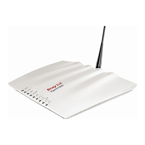
Page 8: Led Indicators And Connectors
Status Explanation The firewall function is active. Firewall blinking When encountering DoS attacks. When detecting one or more user-defined E-mails existing E-mail blinking on mail server. A normal 10Mbps connection is through its corresponding orange port. A normal 100Mbps connection is through its green corresponding port. -
Page 9: Front And Rear View For Vigor2100Vg
Status Explanation The Wireless LAN function is active. WLAN blinking Data packets are transmitted over Wireless LAN. When detecting one or more user-defined e-mails existing E-mail blinking on mail server. A normal 10Mbps connection is through its corresponding orange port. A normal 100Mbps connection is through its green corresponding port. -
Page 10: Front And Rear View For Vigor2100G
Status Explanation The Wireless LAN function is active. WLAN blinking Data packets are transmitted over Wireless LAN. When detecting one or more user-defined e-mails existing E-mail blinking on mail server. A normal 10Mbps connection is through its corresponding orange port. A normal 100Mbps connection is through its green corresponding port. -
Page 11: Hardware Installation
Before starting to configure the router, you have to connect your devices correctly. Connect this device to a router with an Ethernet cable. Connect one port of 4-port switch to your computer with a RJ-45 cable. This device allows you to connect 4 PCs directly. Connect one end of the power cord to the power port of this device. - Page 12 This page is left blank. Vigor2100 Series User’s Guide...
-
Page 13: Configuring Basic Settings
For use the router properly, it is necessary for you to change the password of web configuration for security and adjust primary basic settings. This chapter explains how to setup a password for an administrator and how to adjust basic settings for accessing Internet successfully. - Page 14 Go to System Maintenance page and choose Administrator Password. Enter the login password (the default is blank) on the field of Old Password. Type a new one in the field of New Password and retype it on the field of Retype New Password. Then click OK to continue.
-
Page 15: Quick Start Wizard
If your router can be under an environment with high speed NAT, the configuration provide here can help you to deploy and use the router quickly. The first screen of Quick Start Wizard is entering login password. After typing the password, please click Next. Select the appropriate time zone for your location. -
Page 16: Selecting Internet Access Type
In the Quick Start Wizard, you can configure the router to access the Internet with different protocol/modes such as PPPoE, PPPTP, Static IP or DHCP. The router supports the Ethernet WAN interface for Internet access. PPPoE stands for Point-to-Point Protocol over Ethernet. It relies on two widely accepted standards: PPP and Ethernet. - Page 17 User Name Assign a specific valid user name provided by the ISP. Password Assign a valid password provided by the ISP. Retype Password Retype the password. Always On Check this box to allow the router connecting to Internet forever. Dial On Demand Idle Timeout - Type in the value (unit is second) as the idle timeout of the connection.
- Page 18 For PPTP connection, please click PPTP as the protocol. User Name Assign a specific valid user name provided by the ISP. Password Assign a valid password provided by the ISP. Retype Password Retype the password. Obtain an IP address Click this selection to get the IP address from the router automatically automatically.
- Page 19 Click Finish. Click Static IP as the protocol. Type in all the information that your ISP provides for this protocol. WAN IP Type the WAN IP address that obtained from ISP. Subnet Mask Type the subnet mask obtained from ISP. Gateway Type the gateway address obtained from ISP.
- Page 20 After finishing the settings in this page, click Next to see the following page. Click Finish. The online status of this protocol will be shown as below. Vigor2100 Series User’s Guide...
- Page 21 Click DHCP as the protocol. Type in all the information that your ISP provides for this protocol. Host Name Specify the host name for the router. This is an optional setting. The router will detect the MAC address automatically. If not, click Clone MAC Address to obtain it.
-
Page 22: Online Status For Each Protocol
The online status shows the system status, WAN status, ADSL Information and other status related to this router within one page. If you select PPPoE as the protocol, you will find out a button of Dial PPPoE in the Online Status web page. Online status for PPPoE Online status for DHCP Vigor2100 Series User’s Guide... - Page 23 Online status for Static IP Primary DNS Displays the assigned IP address of the primary DNS. Secondary DNS Displays the assigned IP address of the secondary DNS. IP Address (in LAN) Displays the IP address of the LAN interface. TX Packets Displays the total transmitted packets at the LAN interface.
-
Page 24: Status Bar
Each time you click OK on the web page for saving the configuration, you can find messages showing the system interaction with you. Ready indicates the system is ready for you to input settings. Settings Saved means your settings are saved once you click Finish or OK button. Vigor2100 Series User’s Guide... -
Page 25: Advanced Web Configuration
After finished basic configuration of the router, you can access Internet with ease. For the people who want to adjust more settings for suiting his/her request, please refer to this chapter for getting detailed information about the advanced configuration of this router. As for other examples of application, please refer to Chapter 4. -
Page 26: Pppoe
As a CPE device, Vigor router encapsulates the PPP session based for transport across the ADSL loop and your ISP’s Digital Subscriber Line Access Multiplexer (SDLAM). To choose PPPoE as the accessing protocol of the internet, please select PPPoE from the Internet Access menu. -
Page 27: Static Or Dynamic Ip
Fixed IP – Click Yes to use this function and type in a fixed IP address in the box. WAN physical type Check and choose a proper type used for duplex between this device and other router that you want to communicate. Both sides should use the same physical type;... - Page 28 Keep WAN Normally, this function is designed for Dynamic IP environments Connection because some ISPs will drop connections if there is no traffic within certain periods of time. Check Enable PING to keep alive box to activate this function. PING to the IP - If you enable the PING function, please specify the IP address for the system to PING it for keeping alive.
- Page 29 Specify an IP address – Click this radio button to specify some data if you want to use Static IP mode. IP Address – Type the IP address. Subnet Mask – Type the subnet mask. Gateway IP Address – Type the gateway IP address. DNS Server IP Type in the primary IP address for the router if you want to use Address...
-
Page 30: Pptp
To choose PPTP as the accessing protocol of the internet, please select Internet Access Setup on the Quick Setup page. Next, choose the PPTP link. The following web page will be shown. PPTP Setup PPTP Link - Click Enable to enable a PPTP client to establish a tunnel to a DSL modem on the WAN interface. -
Page 31: Lan
failed due to inconsistent type. It is recommended for you to set Auto negotiation as the physical type. Local Area Network (LAN) is a group of subnets regulated and ruled by router. The design of network structure is related to what type of public IP addresses coming from your ISP. The most generic function of Vigor router is NAT. -
Page 32: Lan Tcp/Ip And Dhcp
Vigor router will exchange routing information with neighboring routers using the RIP to accomplish IP routing. This allows users to change the information of the router such as IP address and the routers will automatically inform for each other. When you have several subnets in your LAN, sometimes a more effective and quicker way for connection is the Static routes function rather than other method. - Page 33 DHCP Server DHCP stands for Dynamic Host Configuration Protocol. The Configuration router by factory default acts a DHCP server for your network so it automatically dispatch related IP settings to any local user configured as a DHCP client. It is highly recommended that you leave the router enabled as a DHCP server if you do not have a DHCP server for your network.
-
Page 34: Nat
If the IP address of a domain name is already in the DNS cache, the router will resolve the domain name immediately. Otherwise, the router forwards the DNS query packet to the external DNS server by establishing a WAN connection. There are two common scenarios of LAN settings that stated in Chapter 4. - Page 35 The port redirection can only apply to incoming traffic. To use this function, please go to NAT page and choose Port Redirection web page. The Port Redirection Table provides 10 port-mapping entries for the internal hosts. Service Name Enter the description of the specific network service. Protocol Select the transport layer protocol (TCP or UDP).
-
Page 36: Dmz Host
For example, the built-in web configurator in the router is with default port 80, which may conflict with the web server in the local network, http://192.168.1.13:80. Therefore, you need to change the router’s http port to any one other than the default port 80 to avoid conflict, such as 8080. - Page 37 Click DMZ Host to open the following page: Private IP If you choose Private IP as the selection for DMZ host, please type in private IP or select any one by clicking the Choose PC button. If you previously have set up WAN Alias in Internet Access>>PPPoE, you will find them in Aux.
-
Page 38: Open Ports
setting. Open Ports allows you to open a range of ports for the traffic of special applications. Common application of Open Ports includes P2P application (e.g., BT, KaZaA, Gnutella, WinMX, eMule and others), Internet Camera etc. Ensure that you keep the application involved up-to-date to avoid falling victim to any security exploits. -
Page 39: Well-Known Ports List
To add or edit port settings, click one index number on the page. The configuration page for that index will be shown on the top side of this page. For each index entry, you can specify 10 port ranges for diverse services. Enable Open Ports Check to enable this entry. - Page 40 If you did not set password during installation; you can go to System Maintenance to set up your password. The users on the LAN are provided with secured protection by the following firewall facilities: User-configurable IP filter (Call Filter/ Data Filter). Stateful Packet Inspection (SPI): tracks packets and denies unsolicited incoming data Selectable Denial of Service (DoS) /Distributed DoS (DDoS) attacks protection URL Content Filter...
- Page 41 Stateful inspection is a firewall architecture that works at the network layer. Unlike legacy static packet filtering, which examines a packet based on the information in its header, stateful inspection builds up a state machine to track each connection traversing all interfaces of the firewall and makes sure they are valid.
- Page 42 The DoS Defense function enables the Vigor router to inspect every incoming packet based on the attack signature database. Any malicious packet that might duplicate itself to paralyze the host in the secure LAN will be strictly blocked and a Syslog message will be sent as warning, if you set up Syslog server.
-
Page 43: General Setup
that this action will not introduce any delay in your Web surfing because each of multiple load balanced database servers can handle millions of requests for categorization. Below shows the menu items of Firewall. General Setup allows you to adjust settings of IP Filter and common options. Here you can enable or disable the Call Filter or Data Filter. -
Page 44: Filter Setup
Some on-line games (for example: Half Life) will use lots of fragmented UDP packets to transfer game data. Instinctively as a secure firewall, Vigor router will reject these fragmented packets to prevent attack unless you enable Accept Incoming Fragmented UDP Packets. By checking this box, you can play these kinds of on-line games. - Page 45 refer to the following page. Active Enable or disable the filter rule. Comment Enter filter set comments/description. Maximum length is 23–character long Next Filter Set Set the link to the next filter set to be executed after the current filter run.
- Page 46 Duplicate to LAN If you want to log the matched packets to another network device, check this box to enable it. The MAC Address of the specified network device or PC is defined in Firewall >>General Setup >> MAC Address for Logged Packets Duplication. Branch to other Filter If the packet matches the filter rule, the next filter rule will branch to the specified filter set.
- Page 47 This section will show a simple example to restrict someone from accessing WWW services. In this example, we assume the IP address of the access-restricted user is 192.168.1.10. The filter rule is created in the Data Filter set and is shown as below. Port 80 is the HTTP protocol port number for WWW services.
-
Page 48: Dos Defense
As a sub-functionality of IP Filter/Firewall, there are 15 types of detect/ defense function in the DoS Defense setup. The DoS Defense functionality is disabled for default. Click Firewall and click DoS Defense to open the setup page. Enable Dos Defense Check the box to activate the DoS Defense Functionality. - Page 49 Enable PortScan Port Scan attacks the Vigor router by sending lots of packets to detection many ports in an attempt to find ignorant services would respond. Check the box to activate the Port Scan detection. Whenever detecting this malicious exploration behavior by monitoring the port-scanning Threshold rate, the Vigor router will send out a warning.
-
Page 50: Url Content Filter
Block Unknown Check the box to activate the Block Unknown Protocol function. Protocol Individual IP packet has a protocol field in the datagram header to indicate the protocol type running over the upper layer. However, the protocol types greater than 100 are reserved and undefined at this time. - Page 51 Click Firewall and click URL Content Filter to open the setup page. Enable URL Access Check the box to activate URL Access Control. Control Keyword The Vigor router provides 8 frames for users to define keywords and each frame supports multiple keywords. The keyword could be a noun, a partial noun, or a complete URL string.
- Page 52 the blocking keyword list, the more efficiently the Vigor router perform. Prevent web access Check the box to deny any web surfing activity using IP address, from IP address such as http://202.6.3.2. The reason for this is to prevent someone dodges the URL Access Control.
-
Page 53: Mac Address Control
and Wednesday). Other days the URL content filtering facility will be silent. If you want your kids not to be addicted to on-line gaming, you apply the URL content filtering facility to your router and you set time schedule for school days in order to let your kids have good sleep. -
Page 54: Applications
Setup group setup. If the four boxes are left blank, that means the traffic for the MAC address is “always pass”. If only one disabled schedule typed in the box, it means the related MAC address will be always blocked. For hosts not listed in This setting allows you to set for all other hosts that not listed in this table... - Page 55 Select Index number 1 to add an account for the router. Then, check Enable Dynamic DNS Account, and choose correct Service Provider: dyndns.org, type the registered hostname: hostname and domain name suffix: dyndns.org in the Domain Name block. The following two blocks should be typed your account Login Name: test and Password: test.
-
Page 56: Call Schedule
Click OK button to save and activate the settings. You will see your setting has been saved. The Wildcard and Backup MX features are not supported for all Dynamic DNS providers. You could get more detailed information from their websites. Disable the Function and Clear all Dynamic DNS Accounts In the DDNS setup menu, uncheck Enable Dynamic DNS Setup, and push Clear All button to disable the function and clear all accounts from the router. -
Page 57: Upnp
Enable Schedule Setup Check to enable the schedule. Start Date (yyyy-mm-dd) Specify the starting date of the schedule. Start Time (hh:mm) Specify the starting time of the schedule. Duration Time (hh:mm) Specify the duration (or period) for the schedule. Action Specify which action Call Schedule should apply during the period of the schedule. - Page 58 Enable UPNP Service Accordingly, you can enable either the Connection Control Service or Connection Status Service. After setting Enable UPNP Service setting, an icon of IP Broadband Connection on Router on Windows XP/Network Connections will appear. The connection status and control status will be able to be activated.
- Page 59 The reminder as regards concern about Firewall and UPnP: Can't work with Firewall Software Enabling firewall applications on your PC may cause the UPnP function not working properly. This is because these applications will block the accessing ability of some network ports. Security Considerations Activating the UPnP function on your network may incur some security threats.
-
Page 60: Email Detection
The router can help you detect whether any new email on the assigned mail account. Up to 5 mail accounts can be set. To set email detection, please click any index, say Index No. 1. Then adjust the detailed setting for that one on the field just above E-mail Detection Configuration. User Name Type the user name or mail account name. -
Page 61: Voip
Voice over IP network (VoIP) enables you to use your broadband Internet connection to make toll quality voice calls over the Internet. There are many different call signaling protocols, methods by which VoIP devices can talk to each other. The most popular protocols are SIP, MGCP, Megaco and H.323. These protocols are not all compatible with each other (except via a soft-switch server). - Page 62 only have to using dial plan or directly dial your friend’s account name if you are with the same SIP Registrar. Please refer to the Example 1 and 2 in the Calling Scenario. Peer-to-Peer Before calling, you have to know your friend’s IP Address. The Vigor VoIP Routers will build connection between each other.
-
Page 63: Dialplan
This page allows you to set phone book and digit map for the VoIP function. Click the Phone Book and Digit Map links on the page to access into next pages for dialplan settings. In this section, you can set your VoIP contacts in the “phonebook”, called DialPlan. It can help you to make calls quickly and easily by using “speed-dial”... - Page 64 To set phone book of dialplan, please click any index, say Index No. 1. Then adjust the detailed setting for that one on the field just above DialPlan Configuration. Enable Click this to enable this entry. Phone Number The speed-dial number of this index. This can be any number you choose, using digits 0-9 and * .
-
Page 65: Sip Accounts
Enable Check this box to invoke this setting. Prefix Number The phone number set here is used to add, strip, or replace the OP number. Mode None - No action. Add - When you choose this mode, the OP number will be added with the prefix number for calling out through the specific VoIP interface. - Page 66 Index Click this link to access into next page for setting SIP account. Profile Display the profile name of the account. Domain/Realm Display the domain name or IP address of the SIP registrar server. Proxy Display the domain name or IP address of the SIP proxy server. Account Name Display the account name of SIP address before @.
- Page 67 Profile Name Assign a name for this profile for identifying. You can type similar name with the domain. For example, if the domain name is draytel.org, then you might set draytel-1 in this field. Register via If you do not want to register for VoIP phone, please choose None. In addition, some SIP server allows users to use VoIP function without registering.
-
Page 68: Phone Settings
Ring Pattern Choose a ring tone type for the VoIP phone call. Below shows successful SIP accounts for your reference. This page allows user to set phone settings for VoIP 1. Symmetric RTP – Check this box to invoke the function. To make the data transmission going through on both ends of local router and remote router not misleading due to IP lost (for example, sending data from the public IP of remote router to the private IP of local... - Page 69 The default value is 10050. Dynamic RTP port end - Specifies the end port for RTP stream. The default value is 15000. RTP TOS – It decides the level of VoIP package. Use the drop down list to choose any one of them. Click the number 1 link under Index column, you can access into the following page for configuring Phone settings.
- Page 70 Call Forwarding There are four options for you to choose. Disable is to close call forwarding function. Always means all the incoming calls will be forwarded into SIP URL without any reason. Busy means the incoming calls will be forwarded into SIP URL only when the local system is busy.
- Page 71 Voice Active Detector - This function can detect if the voice on both sides is active or not. If not, the router will do something to save the bandwidth for other using. Click On to invoke this function; click off to close the function. Default SIP Account There are six groups of SIP accounts that you can set.
- Page 72 cannot find out a suitable one, please choose User Defined and fill out the corresponding values for dial tone, ringing tone, busy tone, congestion tone by yourself for VoIP phone. Also, you can specify each field for your necessity. It is recommended for you to use the default settings for VoIP communication.
-
Page 73: Status
On VoIP call status, you can find codec, connection and other important call status for both ports of VoIP 1 and 2. Refresh Seconds Specify the interval of refresh time to obtain the latest VoIP calling information. The information will update immediately when the Refresh button is clicked. -
Page 74: Qos
Speaker Gain The volume of present call. Display logs of VoIP calls. This setting allows you to set upstream to have high priority for VoIP call. Vigor2100 Series User’s Guide... -
Page 75: Wireless Lan
Note: This function is used for G models only. Over recent years, the market for wireless communications has enjoyed tremendous growth. Wireless technology now reaches or is capable of reaching virtually every location on the surface of the earth. Hundreds of millions of people exchange information every day via wireless communication products. - Page 76 In WPA-Personal, a pre-defined key is used for encryption during data transmission. WPA applies Temporal Key Integrity Protocol (TKIP) for data encryption while WPA2 applies AES. The WPA-Enterprise combines not only encryption but also authentication. Since WEP has been proved vulnerable, you may consider using WPA for the most secure connection.
-
Page 77: General Settings
Separate the Wireless and the Wired LAN- WLAN Isolation enables you to isolate your wireless LAN from wired LAN for either quarantine or limit access reasons. To isolate means neither of the parties can access each other. To elaborate an example for business use, you may set up a wireless LAN for visitors only so they can connect to Internet without hassle of the confidential information leakage. - Page 78 11b only-The router communicates with standard 802.11b STAs. Scheduler (1-15) Set the wireless LAN to work at certain time interval only. You may choose up to 4 schedules out of the 15 schedules pre-defined in Applications >> Schedule setup. The default setting of this filed is blank and the function will always work.
-
Page 79: Security
By clicking the Security Settings, a new web page will appear so that you could configure the settings of WEP and WPA. Mode Disable-Turn off the encryption mechanism. For the security of your router, please select any one of the encryption mode here. WEP-Accepts only WEP clients and the encryption key should be entered in WEP Key. -
Page 80: Access Control
For key length 128 bits - For 128 bits WEP key, either 13 ASCII characters, such as ABCDEFGHIJKLM. (or 26 hexadecimal digits leading by 0x, such as 0x4142434445464748494A4B4C4D) All wireless devices must support the same WEP encryption bit size and have the same key. Four keys can be entered here, but only one key can be selected at a time. -
Page 81: Wds
Remove Delete the selected MAC address in the list. Edit Edit the selected MAC address in the list. Cancel Give up the access control set up. Click it to save the access control list. Clear All Clean all entries in the MAC address list. WDS means Wireless Distribution System. - Page 82 The major difference between these two modes is that: while in Repeater mode, the packets received from one peer AP can be repeated to another peer AP through WDS links. Yet in Bridge mode, packets received from a WDS link will only be forwarded to local wired or wireless hosts.
-
Page 83: Ap Discovery
Check this box to use the same key set in Security Settings page. If you did not set any key in Security Settings page, this check box will be dimmed. Settings Encryption Mode - If you checked the box of Use the same WEP key …, you do not need to choose 64-bit or 128-bit as the Encryption Mode. -
Page 84: Station List
Scan It is used to discover all the connected AP. The results will be shown on the box above this button. Statistics It displays the statistics for the channels used by APs. If you want the found AP applying the WDS settings, please type in the AP’s MAC address on the bottom of the page and click Add. -
Page 85: System Maintenance
For the system setup, there are several items that you have to know the way of configuration: Status, Administrator Password, Configuration Backup, Syslog, Time and Date, Reboot System and Firmware Upgrade. The System Status provides basic network settings of Vigor router. It includes LAN and WAN interface information. -
Page 86: Administrator Password
MAC Address Displays the MAC address of the WAN Interface. IP Address Displays the IP address of the WAN interface. Connection Displays the connection mode of WAN interface. Default Gateway Displays the assigned IP address of the default gateway. Displays the assigned IP address of the primary DNS. MAC Address Displays the MAC address of the wireless Interface. - Page 87 Click Backup button to get into the following dialog. Click Save button to open another dialog for saving configuration as a file. In Save As dialog, the default filename is config.cfg. You could give it another name by yourself. Click Save button, the configuration will download automatically to your computer as a file named config.cfg.
-
Page 88: Syslog
Click Browse button to choose the correct configuration file for uploading to the router. Click Restore button and wait for few seconds, the following picture will tell you that the restoration procedure is successful. SysLog function is provided to help users to monitor router. There is no bother to directly get into the Web Configurator of the router or borrow debug equipments. -
Page 89: Time Setup
From the Syslog screen, select the router you want to monitor. Be reminded that in Network Information, select the network adapter used to connect to the router. Otherwise, you won’t succeed in retrieving information from the router. It allows you to specify where the time of the router should be inquired from. Current System Time Click Inquire Time to get the current time. -
Page 90: Management Setup
Time Zone Select the time zone where the router is located. Enable Daylight Saving Check this box to invoke daylight saving function. Automatically Update Select a time interval for updating from the NTP server. Interval Click OK to save these settings. This page allows you to manage the settings for access control, access list, and port setup. -
Page 91: Firmware Upgrade
Note that this example is running over Windows OS (Operating System). Download the newest firmware from DrayTek's web site or FTP site. The DrayTek web site is www.draytek.com (or local DrayTek's web site) and FTP site is ftp.draytek.com. -
Page 92: Diagnostics
Diagnostic Tools provide a useful way to view or diagnose the status of your Vigor router. Click Diagnostics and click PPPoE/PPTP Diagnostics to open the web page. Refresh To obtain the latest information, click here to reload the page. Broadband Access Display the broadband access mode and status. -
Page 93: Arp Cache Table
Click Diagnostics and click ARP Cache Table to view the content of the ARP (Address Resolution Protocol) cache held in the router. The table shows a mapping between an Ethernet hardware address (MAC Address) and an IP address. Refresh Click it to reload the page. Clear Click it to clear the whole table. -
Page 94: Application And Examples
– – An example of default setting and the corresponding deployment are shown below. The default Vigor router private IP address/Subnet Mask is 192.168.1.1/255.255.255.0. The built-in DHCP server is enabled so it assigns every local NATed host an IP address of 192.168.1.x starting from 192.168.1.10. - Page 95 You can just set the settings wrapped inside the red rectangles to fit the request of NAT usage. Vigor2100 Series User’s Guide...
-
Page 96: Calling Scenario For Voip Function
Example 1: Both John and David have SIP Addresses from different service providers. John’s SIP URL: 1234@draytel.org, David’s SIP URL: 4321@iptel.org Settings for John DialPlan index 1 Phone Number: 1111 Display Name: David SIP URL: 4321@iptel.org SIP Accounts Settings --- Profile Name: draytel1 Register via: Auto SIP Port: 5060 (default) - Page 97 Example 2: Both John and David have SIP Addresses from the same service provider. John’s SIP URL: 1234@draytel.org , David’s SIP URL: 4321@draytel.org Settings for John DialPlan index 1 Phone Number: 1111 Display Name: David SIP URL: 4321@draytel.org SIP Accounts Settings --- Profile Name: draytel 1 Register via: Auto SIP Port: 5060 (default)
-
Page 98: Peer-To-Peer Calling
Example 3: Arnor and Paulin have Vigor routers respectively, they can call each other without SIP Registrar. First they must have each other’s IP address and assign an Account Name for the port used for calling. Arnor’s SIP URL: 1234@214.61.172.53 Paulin’s SIP URL: 4321@ 203.69.175.24 Settings for Arnor DialPlan index 1... -
Page 99: Upgrade Firmware For Your Router
4. The file RTSxxx.exe will be asked to copy onto your computer. Remember the place of storing the execution file. 5. Go to www.draytek.com to find out the newly update firmware for your router. 6. Access into Support Center >> Downloads. Find out the model name of the router and click the firmware link. - Page 100 9. Double click on the icon of router tool. The setup wizard will appear. 10. Follow the onscreen instructions to install the tool. Finally, click Finish to end the installation. 11. From the Start menu, open Programs and choose Router Tools XXX >> Firmware Upgrade Utility.
- Page 101 14. Click Send. 15. Now the firmware update is finished. Vigor2100 Series User’s Guide...
-
Page 102: Trouble Shooting
This section will guide you to solve abnormal situations if you cannot access into the Internet after installing the router and finishing the web configuration. Please follow sections below to check your basic installation status stage by stage. Checking if the hardware status is OK or not. Checking if the network connection settings on your computer are OK or not. - Page 103 The example is based on Windows XP. As to the examples for other operation systems, please refer to the similar steps or find support notes in www.draytek.com. Go to Control Panel and then double-click on Network Connections. Right-click on Local Area Connection and click on Properties.
- Page 104 Select Obtain an IP address automatically and Obtain DNS server address automatically. Double click on the current used MacOs on the desktop. Open the Application folder and get into Network. On the Network screen, select Using DHCP from the drop down list of Configure IPv4. Vigor2100 Series User’s Guide...
-
Page 105: Pinging The Router From Your Computer
The default gateway IP address of the router is 192.168.1.1. For some reason, you might need to use “ping” command to check the link status of the router. The most important thing is that the computer will receive a reply from 192.168.1.1. If not, please check the IP address of your computer. -
Page 106: Checking If The Isp Settings Are Ok Or Not
Click Internet Access group and then check whether the ISP settings are set correctly. Check if the Enable option is selected. Check if Username and Password are entered with correct values that you got from your ISP. Vigor2100 Series User’s Guide... - Page 107 Check if the Enable option for Broadband Access is selected. Check if WAN IP Network Settings is set appropriately. Check if IP Address, Subnet Mask and Gateway are set correctly (must identify with the values from your ISP) if you choose Specify an IP address. Vigor2100 Series User’s Guide...
-
Page 108: Backing To Factory Default Setting If Necessary
Check if the Enable option for PPTP Link is selected. Check if PPTP Server, Username, and Password are set correctly (must identify with the values from your ISP). Check if LAN2/WAN IP Network Settings are set properly. If you select Specify an IP address, you have to type in the values of IP Address and Subnet Mask manually. - Page 109 After restore the factory default setting, you can configure the settings for the router again to fit your personal request. If the router still cannot work correctly after trying many efforts, please contact your dealer for further help right away. For any questions, please feel free to send e-mail to support@draytek.com. Vigor2100 Series User’s Guide...