Rangemaster 110 Dual Fuel (Lidded) User's Manual & Installation Instructions
Hide thumbs
Also See for Rangemaster 110 Dual Fuel (Lidded):
- User's manual & installation instructions (40 pages) ,
- User manual (36 pages) ,
- Users manual & installation (36 pages)

Related Manuals for Rangemaster Rangemaster 110 Dual Fuel (Lidded)


Summary of Contents for Rangemaster Rangemaster 110 Dual Fuel (Lidded)
-
Page 1: User Guide
Britain’s No.1 Range Cooker USER GUIDE & INSTALLATION INSTRUCTIONS Classic 110 Dual Fuel (Lidded) Rangemaster 110 Dual Fuel (Lidded) Toledo 110 Dual Fuel (Lidded) - Page 2 We o er cookware to work perfectly with all fuel types manufactured by Rangemaster, including induction hobs. You can be assured of functionality with style, as well as the quality and meticulous attention to detail you expect from the pioneers of range cooking.
-
Page 3: Table Of Contents
Tips on Cooking with the Timer Pressure Testing General Oven Tips Circuit Diagram Cooking Table 10. Technical Data Cleaning Your Cooker Essential Information Hotplate Burners The Griddle Grill Control Panel, Doors and Glass Lid Ovens Classic, Rangemaster & Toledo 110DF U110099-05... -
Page 5: Before You Start
1. Before You Start... This User Guide covers a number of di erent models. If You Smell Gas Although some of the illustrations will look di erent to • DO NOT turn electric switches on or off your particular model the functions will be the same. We •... -
Page 6: Cooker Care
Accessible parts will become hot during use and will NEVER leave a chip pan unattended. Always heat fat retain heat even after you have stopped cooking. slowly, and watch as it heats. Deep fry pans should Keep babies and children away from the cooker and be only one third full of fat. -
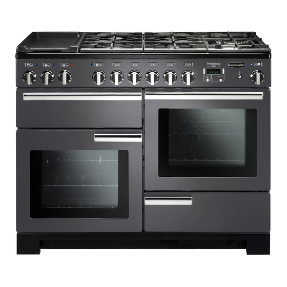
Page 7: Cooker Overview
2. Cooker Overview DocNo.020-0013 - Overview - 110DF - Classic, RM & Toledo lidded Fig.2-1 ArtNo.212-0002 - 110 Classic ceramic front view The 110 dual fuel cooker (Fig.2-1) has the following features: Fig.2-2 Glass lid 5 hotplate burners including a warmer and: –... -
Page 8: Hotplate Burners
Hotplate Burners Fig.2-3 The drawing by each of the central knobs indicates which burner that knob controls. Each burner has an Flame Supervision Device (FSD) that prevents the ow of gas if the ame goes out. When the igniter button is pressed in, sparks will be made at every burner –... -
Page 9: The Wok Cradle (Optional Extra)
Note: The use of aluminium pans may cause metallic marking Fig.2-10 of the pan supports. This does not a ect the durability of the enamel and may be cleaned o with an appropriate metal cleaner. The Wok Cradle (optional extra) The wok cradle is designed to t a Professional 35 cm wok. -
Page 10: Warmer
Warmer Fig.2-16 On the right of the hob is the warmer (Fig.2-16). Use the warmer for keeping food warm while the nal touches are put to a meal. Turn the control knob counter-clockwise to the ‘On’ position. For best results, preheat a covered serving dish for 10 minutes before adding food to it. -
Page 11: The Ovens
The Ovens Fig.2-20 The clock must be set to the time of day before the ovens will work. See the following section on ‘The Clock’ for instructions on setting the time of day. References to ‘left-hand’ and ‘right-hand’ ovens apply as viewed from the front of the appliance. -
Page 12: The Clock
The Clock Fig.2-22 You can use the timer (Fig.2-22) to turn the oven(s) on and o . The clock must be set to the time of day before the oven(s) will work. Setting the Time of Day ArtNo.302-0002 - 6BC annotated When the clock is rst connected the display ashes ( 0.00 ) ... -
Page 13: Manual Cooking
AUTO is Showing, But you Want to Reset to Fig.2-32 Fig.2-33 Manual Cooking To return to manual cooking from any automatic setting, the ‘cook period’ must be cancelled. Press and hold the [] button and then press the [–] button until the display reads ArtNo.302-0009 - Activating ArtNo.302-0008 - the key lock 2... -
Page 14: Accessories
Accessories Fig.2-37 Oven Shelves Flat shelf Shelf guard In addition to the at shelves, some models are supplied with a drop shelf (Fig.2-37). The drop shelf increases the possibilities for oven shelf spacing. The oven shelves can be easily removed and re tted. Front Pull the shelf forward until the back of the shelf is stopped by the shelf stop bumps in the oven sides (Fig.2-38). -
Page 15: Cooking Tips
3. Cooking Tips Tips on Cooking with the Timer General Oven Tips If you want to cook more than one dish, choose dishes that The wire shelves should always be pushed rmly to the back require approximately the same cooking time. However, of the oven. -
Page 16: Cooking Table
4. Cooking Table DocNo.031-0004 - Cooking table - electric & fan single cavity The oven control settings and cooking times given in the table below are intended to be used Top (T) AS A GUIDE ONLY. Individual tastes may require the temperature to be altered to provide a preferred result. -
Page 17: Cleaning Your Cooker Essential Information
5. Cleaning Your Cooker Essential Information Fig.5-1 Isolate the electricity supply before carrying out any thorough cleaning. Allow the cooker to cool. NEVER use paint solvents, washing soda, caustic cleaners, biological powders, bleach, chlorine based bleach cleaners, coarse abrasives or salt. DO NOT mix di erent cleaning products –... -
Page 18: Grill
Grill Fig.5-5 The grill pan and trivet should be washed in hot soapy water. Alternatively, the grill pan can be washed in a dishwasher. After grilling meats or any foods that soil, leave to soak for a few minutes immediately after use. Stubborn particles may be removed from the trivet using a nylon brush. -
Page 19: Cleaning Table
DO NOT use steel wool, oven cleaning pads, or any Cleaning Table other materials that will scratch the surface. Cleaners listed (Table 5-1) are available from supermarkets or electrical retailers as stated. Removing the Main Oven Linings Some of the lining panels can be removed for cleaning. For enamelled surfaces use a cleaner that is approved for use on vitreous enamel. -
Page 20: Troubleshooting
6. Troubleshooting Hotplate ignition or hotplate burners faulty Power failure Is the power on? Is the clock illuminated? In the event of a failure in the electrical supply, remember to reset the clock to make sure that the If not, there maybe something wrong with the power timed oven continues to operate. - Page 21 An oven light is not working Fig.6-1 The bulb has probably burnt out. You can buy a replacement bulb (which is not covered under the warranty) from a good electrical shop. Ask for a 15 W – ArtNo.324-0005 Oven light bulb 230 V lamp, FOR OVENS.
-
Page 22: Installation
INSTALLATION Check the appliance is electrically safe and gas sound when you have nished. 7. Installation Dear Installer In the UK: The regulations and standards are as follows: Before you start your installation, please complete the details below, so that, if your customer has a problem relating to In your own interest and that of safety, it is law that all your installation, they will be able to contact you easily. -
Page 23: Location Of Cooker
INSTALLATION Check the appliance is electrically safe and gas sound when you have nished. Checking the Parts: Location of Cooker The cooker may be installed in a kitchen/kitchen diner but 3 pan supports (Classic shown) Plinth (1-piece model shown) NOT in a room containing a bath or shower. This appliance is designed for domestic cooking only. -
Page 24: Positioning The Cooker
INSTALLATION Check the appliance is electrically safe and gas sound when you have nished. Positioning the Cooker Fig.7-1 Fig.7-1 and Fig.7-2 show the minimum recommended 75 mm 75 mm distance from the cooker to nearby surfaces. 650 mm The cooker should not be placed on a base. The hotplate surround should be level with, or above, any adjacent work surface. -
Page 25: Moving The Cooker
INSTALLATION Check the appliance is electrically safe and gas sound when you have nished. Moving the Cooker Fig.7-6 On no account try and move the cooker while it is plugged into the electricity supply. The cooker is very heavy, so take great care. We recommend that two people manoeuvre the cooker. -
Page 26: Repositioning The Cooker Following Connection
INSTALLATION Check the appliance is electrically safe and gas sound when you have nished. Repositioning the Cooker Following Fig.7-11 Connection If you need to move the cooker once it has been connected then you need to unplug it and, having gripped under the fascia panel and lifted the front of the cooker slightly (Fig.7-7), you need to check behind the cooker to make sure ArtNo.215-0026 - Handle gaskets fixed... -
Page 27: Gas Connection
INSTALLATION Check the appliance is electrically safe and gas sound when you have nished. Gas Connection Fig.7-14 This must be in accordance with the relevant standards. Position for gas The exible hose (not supplied with the cooker) must be supply connector in accordance with the relevant standards. -
Page 28: Electrical Connection
INSTALLATION Check the appliance is electrically safe and gas sound when you have nished. Electrical Connection Fig.7-15 The cooker must be installed by a quali ed electrician, in accordance with all relevant British Standards/Codes of Practice (in particular BS 7671), or with the relevant national and local regulations. -
Page 29: Conversion To Lp Gas
Lift the control panel and pull forwards, taking care not to damage or strain the wiring. Rangemaster & Toledo – Removing the Control Panel Pull o all the control knobs and remove the xing screws underneath the control panel. -
Page 30: Stick On Label
WARNING – SERVICING TO BE CARRIED OUT ONLY BY AN AUTHORISED PERSON Disconnect from electricity and gas before servicing. Check appliance is safe when you have nished. Stick on Label Stick the LP gas label over the natural gas part of the appliance data label. -
Page 31: Circuit Diagram
9. Circuit Diagram P095199 P025635 P093292 The connections shown in the circuit diagram are for single-phase. The ratings are for 230 V 50 Hz. Code Description Code Colour Code Description Grill control Blue Warmer control Grill element left-hand side Brown Warmer Grill element right-hand side Black... -
Page 32: Technical Data
10. Technical Data ArtNo.107-0005 - Technical data - 90DF - Classic DL THE COOKER IS CATEGORY: CatII 2H3+ It is supplied set for group H natural gas. A conversion kit from NG to LP is available for the cooker. INSTALLER: Please leave these instructions with the user. DATA BADGE LOCATION: Cooker back, serial number repeater badge below oven door opening. - Page 33 Notes...
- Page 34 Notes...
- Page 35 Gas Safe registered engineer for gas appliances or an approved electrician for electrical models. CONSUMER SERVICE For a competitive quote and to arrange for a Rangemaster approved If you have any product enquiries, or in the event of a problem engineer to attend, call Consumer Services on: 0870 7895107.
- Page 36 Registered in England and Wales. Registration No. 354715 Registered O ce: Juno Drive, Leamington Spa, Warwickshire, CV31 3RG Rangemaster continuously seeks improvements in speci cation, design and production of products and thus, alterations take place periodically. Whilst every e ort is made to produce up-to-date literature, this booklet should not be regarded as an infallible guide to...