
Related Manuals for Rangemaster Hi-LITE 110DF


Summary of Contents for Rangemaster Hi-LITE 110DF
-
Page 1: User Guide
Britain’s No.1 Range Cooker USER GUIDE & INSTALLATION INSTRUCTIONS Hi-LITE 110 Dual Fuel... - Page 2 We offer cookware to work perfectly with all fuel types manufactured by Rangemaster, including induction hobs. You can be assured of functionality with style, as well as the quality and meticulous attention to detail you expect from the pioneers of range cooking.
-
Page 3: Table Of Contents
Oven Lights Final Checks Storage Fitting the Plinth Cooking Tips Customer Care Tips on Cooking with the Timer Conversion to LP Gas General Oven Tips Hotplate Cooking Table Affix Label Pressure Testing Circuit Diagram 10. Technical Data Hi-LITE 110DF U110299-01C... -
Page 5: Before You Start
1. Before You Start... If you smell gas Your cooker should give you many years of trouble-free cooking if installed and operated correctly. It is important • DO NOT turn electric switches on or off. that you read this section before you start, particularly if you •... -
Page 6: Ceramic Warming Zone
NEVER leave a chip pan unattended. Always heat fat Accessible parts will become hot during use and will slowly, and watch as it heats. Deep fry pans should retain heat even after you have stopped cooking. be only one third full of fat. Filling the pan too full Keep babies and children away from the cooker and of fat can cause spill over when food is added. -
Page 7: Cooker Care
Take care NOT to place metallic objects such as knives, forks, spoons and lids on the hob surface Fig.1.1 since they can get hot. The appliance is not intended to be operated by means of external timer or separated remote-control system. -
Page 8: Cooker Overview
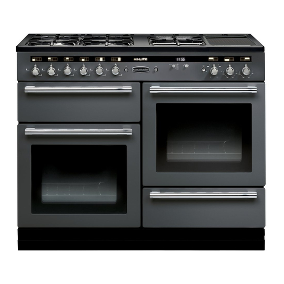
2. Cooker Overview DocNo.020-0013 - Overview - 110DF - Classic, RM & Toledo lidded Fig.2.1 100 220 The 110 dual fuel cooker (Fig.2-1) has the following features: Fig.2.2 4 hotplate burners, a warming zone and wok burner A control panel A grill Conventional oven Fan oven... -
Page 9: Wok Burner
The igniter should spark and light the gas. Keep holding the knob pressed in to let the gas through to the burner for about Fig.2.3 ten seconds. If, when you let go of the control knob, the burner goes out, then the FSD has not been bypassed. -
Page 10: The Wok Cradle (Optional)
The Wok Cradle (Optional) Fig.2.9 The wok cradle is designed to fit a 35 cm wok. If you use a different wok, make sure that it fits the cradle. Woks vary very widely in size and shape. It is important that the wok sits down on the pan support –... -
Page 11: Warming Zone
Warming Zone Fig.2.15 On the right of the hob is the warming zone (Fig.2-15). Use the warming zone for keeping food warm while the final touches are put to a meal. Turn the control knob clockwise to the ‘On’ position. For best results, preheat a covered serving dish for 10 minutes before adding food to it. -
Page 12: The Ovens
The Ovens Fig.2.19 The clock must be set to the time of day before the right- hand oven will work. See the following section on ‘The Clock’ for instructions on setting the time of day. References to ‘left-hand’ and ‘right-hand’ ovens apply as viewed from the front of the appliance. -
Page 13: The Clock
The Clock ArtNo.300-0004 2-button clock annotated Fig.2.22 You can use the clock to turn the right-hand oven on and off. The clock must be set to the time of day before the oven will work. Note: When using the timer functions, first set the clock as required before setting the oven temperature. - Page 14 Turn the Timer knob to the [ ] position. The display will ArtNo.301-0008 2BC Fig.2.29 show the current time of day plus the ‘cook time’ you just set. Stopping the oven 2 Use the Adjusting knob to set the ‘stop time’ required (Fig.2-29).
-
Page 15: Accessories
Accessories Fig.2.35 Oven Shelves Shelf guard The oven shelves (Fig.2-35) can be easily removed and refitted. Pull the shelf forward until the back of the shelf is stopped by the shelf stop bumps in the oven sides (Fig.2-36). Front Lift up the front of the shelf so the back of the shelf will pass under the shelf stop and then pull the shelf forward (Fig.2-37). -
Page 16: Cooking Tips
3. Cooking Tips Tips on Cooking with the Timer General Oven Tips If you want to cook more than one dish, choose dishes that The wire shelves should always be pushed firmly to the back require approximately the same cooking time. However, of the oven. -
Page 17: Cooking Table
4. Cooking Table DocNo.031-0004 - Cooking table - electric & fan single cavity The oven control settings and cooking times given in the table below are intended to be used Top (T) AS A GUIDE ONLY. Individual tastes may require the temperature to be altered to provide a ArtNo.050-0007 preferred result. -
Page 18: Cleaning Your Cooker
ArtNo.045-0004 - Cleaning - 90 induction - tpl glzd dr & GO grill 5. Cleaning Your Cooker Essential Information Fig.5.1 Isolate the electricity supply before carrying out any thorough cleaning. Allow the cooker to cool. NEVER use paint solvents, washing soda, caustic cleaners, biological powders, bleach, chlorine based bleach cleaners, coarse abrasives or salt. -
Page 19: Ceramic Warming Zone
The grill pan and trivet should be washed in hot soapy water. Fig.5.5 Alternatively, the grill pan can be washed in a dishwasher Ceramic Warming Zone Daily Care ArtNo.330-0003 - Grill pan w handle pulled forwards First of all, be sure that the heat indicator light is off and that the warming zone surface is cool. -
Page 20: Control Panel And Doors
Control Panel and Doors Fig.5.7 Avoid using any abrasive cleaners, including cream cleaners. For best results, use a liquid detergent. The same cleaner can be used on the doors, or alternatively, using a soft cloth wrung out in clean hot soapy water – but take care that no surplus water seeps into the appliance. -
Page 21: Cleaning Table
Cleaning Table Cleaners listed (Table 5-1) are available from supermarkets or electrical retailers as stated. For enamelled surfaces use a cleaner that is approved for use on vitreous enamel. Regular cleaning is recommended. For easier cleaning, wipe up any spillages immediately. Hotplate Part Finish... -
Page 22: Troubleshooting
6. Troubleshooting Hotplate ignition or hotplate burners faulty Metal markings on the ceramic warming zone surface Is the power on? Is the clock illuminated? Do not slide aluminium or copper pans across the ceramic surface. Marks from aluminium and copper If not, there maybe something wrong with the power pans as well as mineral deposits from water or food can supply. - Page 23 The oven is not cooking evenly Fig.6.1 Do not use a baking tray with dimensions larger than those specified in the section on ‘General Oven Tips’ . If you are cooking a large item, be prepared to turn it ArtNo.324-0005 Oven light bulb round during cooking.
-
Page 24: Installation
INSTALLATION Check the appliance is electrically safe and gas sound when you have finished. 7. Installation Dear Installer In the UK the cooker must be installed in accordance with: Before you start your installation, please complete the details below, so that, if your customer has a problem relating to •... -
Page 25: Location Of Cooker
INSTALLATION Check the appliance is electrically safe and gas sound when you have finished. Location of Cooker Checking the Parts: The cooker may be installed in a kitchen/kitchen diner but 3 pan supports Plinth NOT in a room containing a bath or shower. This appliance is designed for domestic cooking only. -
Page 26: Positioning The Cooker
INSTALLATION Check the appliance is electrically safe and gas sound when you have finished. Positioning the Cooker Fig.7.1 Fig.7.1and Fig.7.2 show the minimum recommended 75 mm 75 mm distance from the cooker to nearby surfaces. 650 mm The cooker should not be placed on a base. The hotplate surround should be level with, or above, any adjacent work surface. -
Page 27: Fitting The Stability Bracket Or Chain
INSTALLATION Check the appliance is electrically safe and gas sound when you have finished. Lowering the Two Rear Rollers Fig.7.5 To adjust the height of the rear of the cooker, first fit a 13 mm spanner or socket wrench onto the hexagonal adjusting nut (Fig.7.5). -
Page 28: Gas Connection
INSTALLATION Check the appliance is electrically safe and gas sound when you have finished. Gas Connection Fig.7.10 This must be in accordance with the relevant standards. Position for gas The flexible hose (not supplied with the cooker) must be supply connector in accordance with the relevant standards. -
Page 29: Final Checks
INSTALLATION Check the appliance is electrically safe and gas sound when you have finished. Current Operated Earth Leakage Breakers Fig.7.11 The combined use of your cooker and other domestic appliances may cause nuisance tripping, so we recommend that the cooker is protected on an individual RCD (Residual Current Device) or RCBO (Residual Current Breaker with Overload). -
Page 30: Conversion To Lp Gas
WARNING – SERVICING TO BE CARRIED OUT ONLY BY AN AUTHORISED PERSON Disconnect from electricity and gas before servicing. Check appliance is safe when you have finished. 8. Conversion to LP Gas Check the ‘Technical Data’ section at the back of the book Fig.8.1 that the hob is convertible to the gas you want to use. -
Page 31: Pressure Testing
WARNING – SERVICING TO BE CARRIED OUT ONLY BY AN AUTHORISED PERSON Disconnect from electricity and gas before servicing. Check appliance is safe when you have finished. Pressure Testing Connect the appliance to the gas supply. Check the appliance is gas sound. The gas pressure can be measured at one of the hotplate injectors (not a wok burner). -
Page 32: Circuit Diagram
9. Circuit Diagram P095199 P095199 P057904 P038482 The connections shown in the circuit diagram are for single-phase. The ratings are for 230 V 50 Hz. Description Description Code Colour Illumination Board - Left-hand side Right-hand Oven Fan Blue Grill Front Switch Right-hand Oven Thermal Preset Brown Grill Energy Regulator... -
Page 33: Technical Data
10. Technical Data ArtNo.107-0024 - Technical data - 110DF - Classic-Toledo THE COOKER IS CATEGORY: CatII 2H3+ . It is supplied set for group H natural gas. A conversion kit from NG to LP is available for the cooker. INSTALLER: Please leave these instructions with the user. DATA BADGE LOCATION: Cooker back, serial number repeater badge below oven door opening. - Page 34 Notes...
- Page 35 0800 804 6261 or depending on your mobile network tariff you can For a competitive quote and to arrange for a Rangemaster approved call free on 0370 789 5107. engineer to attend, call Consumer Services on: 0800 804 6261 or...
- Page 36 Registered in England and Wales. Registration No. 354715 Registered Office: Juno Drive, Leamington Spa, Warwickshire, CV31 3RG Rangemaster continuously seeks improvements in specification, design and production of products and thus, alterations take place peri- odically. Whilst every effort is made to produce up-to-date literature, this booklet should not be regarded as an infallible guide to current...