Table of Contents
Advertisement
USER'S MANUAL
Thank you very much for purchasing the EGX-300.
•
To ensure correct and safe usage with a full under-
standing of this product's performance, please be sure
to read through this manual completely and store it in
a safe location.
•
Unauthorized copying or transferral, in whole or in
part, of this manual is prohibited.
•
The contents of this operation manual and the
specifications of this product are subject to change
without notice.
•
The operation manual and the product have been
prepared and tested as much as possible. If you find
any misprint or error, please inform us.
•
Roland DG Corp. assumes no responsibility for any
direct or indirect loss or damage which may occur
through use of this product, regardless of any failure to
perform on the part of this product.
•
Roland DG Corp. assumes no responsibility for any
direct or indirect loss or damage which may occur
with respect to any article made using this product.
Advertisement
Table of Contents

Related Manuals for Roland EGX-300


Summary of Contents for Roland EGX-300
- Page 1 USER'S MANUAL Thank you very much for purchasing the EGX-300. • To ensure correct and safe usage with a full under- standing of this product's performance, please be sure to read through this manual completely and store it in a safe location.
- Page 2 AVIS Cet appareil numérique de la classe A respecte toutes les exigences du Règlement sur le matériel brouilleur du Canada. ROLAND DG CORPORATION 1-6-4 Shinmiyakoda, Hamamatsu-shi, Shizuoka-ken, JAPAN 431-2103 MODEL NAME : See the MODEL given on the rating plate.
-
Page 3: Table Of Contents
Microsoft Corporation in the United States and/or other countries. i486 and Pentium are registered trademarks of Intel Corporation in the United States. IBM is a registered trademark of International Business Corporation. http://www.rolanddg.com/ Copyright © 2001 Roland DG Corporation... -
Page 4: To Ensure Safe Use
(i.e., emitting smoke, burning odor, unusual noise, or the like). Doing so may result in fire or electrical shock. Immediately switch off the power, unplug the power cord from the electrical outlet, and contact your authorized Roland DG Corp. dealer or service center. - Page 5 Do not use with a damaged power When not in use for extended cord or plug, or with a loose periods, unplug the power cord from electrical outlet. the electrical outlet. Use with any other Failure to do so may power supply may result in danger of lead to fire or...
- Page 6 Before attempting to replace the Please use a vacuum cleaner to motor brushes or the spindle motor, remove cutting dust. stop cutting operations on the EGX- Do not use any blower like airbrush. 300 and allow to stand for an hour or Otherwise, dust spread in the air may harm your health.
-
Page 7: About The Labels Affixed To The Unit
About the Labels Affixed to the Unit These labels are affixed to the body of this product. The following figure describes the location and content of these messages. Do not insert your fingers between the heads and the main unit during operation. Handle tool with care. -
Page 8: Pour Utiliser En Toute Sécurité
Pour utiliser en toute sécurité Avis sur les avertissements Utilisé pour avertir l'utilisateur d'un risque de décès ou de blessure grave en cas de mauvaise utilisation de l'appareil. Utilisé pour avertir l'utilisateur d'un risque de blessure ou de dommage matériel en cas de mauvaise utilisation de l'appareil. * Par dommage matériel, il est entendu dommage ou tout autre effet indésirable sur la maison, tous les meubles et même les animaux domestiques. - Page 9 Ne pas utiliser avec une fiche ou un Débrancher le fil lorsque l'appareil fil électrique endommagé ou avec reste inutilisé pendant une longue une prise mal fixée. période. Une négligence à Une négligence à ce niveau pourrait ce niveau pourrait provoquer des décharges électriques, provoquer un...
- Page 10 à axe, les copeaux. N'utiliser aucun interrompre les opérations de coupe appareil soufflant de l'air comme un du EGX-300 et attendre une heure ou sèche-cheveux. plus. La poussière répandue dans l'air pourrait nuire à votre santé.
-
Page 11: À Propos Des Étiquettes Collées Sur L'appareil
À propos des étiquettes collées sur l'appareil Ces étiquettes sont collées à l'extérieur de l'appareil. Les dessins suivants indiquent l'endroit et le contenu des messages. Ne pas insérer les doigts entre les têtes d'impression et l'unité principale lorsque l'appareil fonctionne. Manipuler l'outil avec précaution. - Page 12 MEMO...
-
Page 13: Part 1 Startup
(with cutter holder) Collet Collet Hexagonal screw driver Hexagonal wrench (For diameter 3.175 mm (For diameter 4.36 mm (1/8 in.) cutters) (11/64 in.) cutters) Vacuum adapter set Spare cutter securing screw Adhesive sheet Clamps Motor brushes User's manual Roland Software Package CD-ROM... -
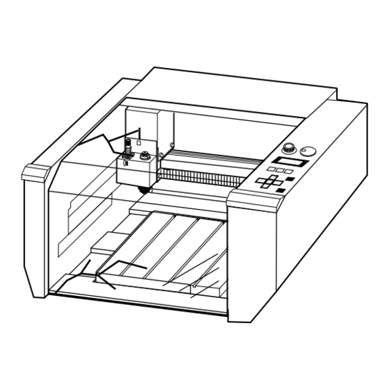
Page 14: Part Names And Functions
Part 1 1-2 Part Names and Functions Cover Left side view When opening the cover during operation, press the [ENTER/PAUSE] key to pause operation. Serial connector Wait until operation stops completely, then open the cover. To resume A serial (RS-232C) operation, close the cover and press the [ENTER/PAUSE] key again. - Page 15 This is used to set the speed of the spindle motor. Liquid-crystal display The settings and selection choices (or values) for the EGX-300 are shown on this display. Error messages also appear here in the event of a problem. MENU key This key scrolls through the menu on the liquid-crystal display (i.e., it changes the panel...
-
Page 16: Installation And Connections
• Avoid use in areas subject to strong electric noise. • Avoid use in areas subject to high humidity or dust. • The EGX-300 generates heat when used, and should not be installed in an area with poor heat radiation characteristics. - Page 17 Part 1 Connections Ground the unit with the ground Do not use with any electrical power wire. supply that does not meet the Failure to do so may result in risk of ratings displayed on the unit. electrical shock in the even of a mechanical Use with any other power supply may lead problem to fire or electrocution.
-
Page 18: Installing The Software
Part 1 1-4 Installing the Software The included CD-ROM contains several pieces of software for operating the EGX-300. Operating environment MODELA Applications Dr. Engrave 3D Engrave Virtual MODELA Computer Personal computer running Windows 95, Windows 98, Windows Me, Windows NT 4.0, or Windows 2000... - Page 19 When you make the settings for the communication for the cable connected to the computer. parameters of EGX-300, make the parameters match the values displayed here. When using an RS-232C (serial) cable Click [Close] to finish installing the driver.
- Page 20 Part 1 How to use Help If you have trouble using the program or driver, see the help screens. Help contains information such as descriptions of software opera- tion, explanations of commands, and tips for using the software more effectively. From the [Help] menu, click [Contents].
-
Page 21: Setting The Connection Parameters
EGX-300 to configure the equipment for the type of connection that has been made. Normally, the setting on the EGX-300 should be made to match the setting on the computer. The steps below describe how to set connection parameters on the EGX-300. -
Page 22: Loading A Workpiece For Cutting
Large-size material (i.e., material that is about the same size as the EGX-300's table) cannot be affixed to the table securely using the adhesive sheet or clamps. In such cases, use commercially available double-sided tape to secure the workpiece in place. -
Page 23: Loading A Cutter
Part 1 Loading Workpiece Using Commercially Double-sided Tape Apply the double-sided tape to the bottom of the workpiece and secure it to the table. Double-sided tape Workpiece 1-7 Loading a Cutter Installing the Cutter holder and Collet NOTICE To install an end mill using the optionally available collet set (ZC-23), detach the blade holder. If you try to perform machining with the blade holder installed, the vibration may make it come loose and fall off. - Page 24 Part 1 When Using the Depth regulator nose Using the depth regulator nose makes it possible to engrave even workpiece of non-uniform thickness at the same depth. Rotate than depth regulator nose in the direction of the This determines the engraving depth (cutting-in arrow 2 in the figure to tighten it completely.
- Page 25 Part 1 Use the height setting made in step 4 to set Z0. Z0 is Insert the cutter into the hole in the cutter holder, and the reference point for raising and lowering the use the hexagonal screwdriver that comes with the spindle.
- Page 26 Part 1 When Not Using the Depth regulator nose If you do not use the depth regulator nose, take a table workpiece made of ABS plastic about 10 mm (1/2 in.) thick, secure it in place on the included table, and perform surface leveling. By using this as the table surface, you can carry out engraving at a uniform depth.
- Page 27 Part 1 Setting the Z0 Position "Z0" is the origin point for the Z axis. This is normally set at a position which corresponds to the surface of the secured workpiece when mounting the cutter. Press the [MENU] key to make the following screen Press the [ENTER] key to make the following screen appear on the display.
-
Page 28: Vacuum Cleaner Connection
Part 1 1-8 Vacuum Cleaner Connection Use a commercially available brush to remove metal cuttings. Attempting to use a vacuum cleaner to take up metal cuttings may cause fire in thevacuum cleaner. NOTICE Use a vacuum cleaner that lets you adjust the amount of suction and is equipped with an overload protector. Always allow a minimum gap of 30 cm (11-13/16 in.) on the side where the vacuum hose exits. -
Page 29: Setting The Origin (Home Position)
The setting method explained here, uses the left, bottom corner (nearest the operator) of the workpiece as the home position. * The home position points are registered in the EGX-300 memory right after power is turned on and before power is turned off. Press the [MENU] key to make the following screen Press the arrow keys and the CUTTER UP/DOWN appear on the display. -
Page 30: Cutting Condition Setting
3. The cutting-in amount (depth of one cutting operation) Note : When settings have been made with both the software and the EGX-300, the last settings made have priority. In this manual, these three conditions are called the cutting conditions. The characteristics and points to consider for each of these conditions are as follows. - Page 31 Part 1 Press the [ ] or [ ] key to set the feed rate. Press the [ENTER] key. Setting range Make sure that “< >” appears. X- and Y-axis : 0.5 to 60 mm/sec Z-axis : 0.5 to 30 mm/sec Spindle Motor Revolution Speed Rotate the spindle control to set the speed of rotation.
- Page 32 Part 1 Cutting Condition Setting Examples The chart below contains reference examples of the appropriate cutting conditions for several types of workpiece material. In the case that the conditions are input using software or when constructing your own programs, set the cutting conditions with reference to the chart.
-
Page 33: Setting The Z1 And Z2 Position
Part 1 1-11 Setting the Z1 and Z2 Position Cutter The cutter up position (Z2 point) and down position (Z1 point) are normally set with the software. If they cannot be set with your current software then set them manually using the keys on the switch panel. -
Page 34: Sending Cutting Data
The tool may break. If machining operation beyond capacity is started inadvertently, immediately press the EMERGENCY STOP switch. If the cover must be opened during cutting, first press the [ENTER/PAUSE] key to pause the EGX-300, then open the cover. After the cover has been closed, cutting resumes when the paused state is canceled. -
Page 35: Finishing
Part 1 1-13 Finishing Do not carelessly insert the hands Please use a vacuum cleaner to while in operation. remove cutting dust. Doing so may result in injury (during manual Do not use any blower like airbrush. operation.). Otherwise, dust spread in the air may harm your health or damage this machine. - Page 36 Part 1 Open the cover and detach the cutter. Remove the workpiece. Head If the material has been secured in place using an adhesive sheet or double-sided tape, peel it off of the bed. Use a commercially available vacuum cleaner to remove chips inside the box.
-
Page 37: Part 2 User's Reference
2-1 Cutting Area The maximum cutting area of the EGX-300 is 305 mm (X) x 230 mm (Y) x 30 mm (Z) (12 in. (X) x 9 in. (Y) x 1-1/8 in. (Z) ). When converted to coordinate values, this corresponds to (x, y, z) = (30500, 23000, 3000) when the coordinate unit is 0.01 mm, or (x, y, z) = (12200, 9200, 3000) when the coordinate unit is 0.025 mm. -
Page 38: Operating Each Function
Part 2 2-2 Operating Each Function Making Settings with the Liquid-crystal Display When coordinate values are displayed: Use the keys to move along the X axis. Use the keys to move along the Y axis. Use the keys to move along the Z axis. Use the keys to move the blinking cursor (“... - Page 39 “CLEAR”.) Executing the “REPEAT” calls up the cutting data stored in the EGX-300's data buffer and executes the replotting procedure. When replotting is executed, the entire data content of the data buffer is called up. When you perform replotting, clear the data from the data buffer before sending the cutting for replotting from the computer.
- Page 40 The feed rate and spindle rotating speed set by the software can be changed while cutting is in progress. This is done by first pausing the EGX-300 during cutting, then changing the feed rate. However, if the computer subsequently sends a command to change the feed rate, the setting will change as specified by the new command.
- Page 41 Part 2 Canceling the Paused State to Resume Cutting After changing the feed rate, cancel the paused state. Cutting then resumes at the new feed rate or spindle speed. Press the [MENU] key to make the following screen Press the [ ] key to move the blinking cursor (“ ”) to appear on the display.
-
Page 42: Explanation Of The Display Menus
Part 2 2-3 Explanation of the Display Menus This shows the current position of the cutter (in coordinates). The coordinate values indicate the home position as the origin point on the X and Y axes, and the Z0 point as the origin point on the Z axis. - Page 43 Part 2 “I/O” Default : AUTO This sets the type of interface connected to the computer. When set to “AUTO,” the interface type (parallel or serial) is determined automatically. However, serial communi- cation parameters (baud rate, parity checking, stop bit, data bit, and handshaking settings) are not determined and must be set.
- Page 44 This selects the action when the cutter returns from a coordinate outside the cutting range to a coordinate inside the range. (The cutter cannot actually be moved outside the cutting range, but the EGX-300's internal processing handles this as if it had.) “CONTINUE”: Operation is not paused upon return to the cutting range. Cutting continues without interruption.
-
Page 45: Maintenance
NOTICE When cleaning the EGX-300, make sure that the main unit's power OFF. When replacing the motor brushes, first touch the table to discharge static electricity from your body. Failure to follow the procedure for discharging static electricity may result in breakdown. - Page 46 Part 2 Replacing the Motor Brushes The brushes for the spindle motor should be replaced periodically. As a general guide, replacement after every 1,000 hours of spindle rotation is suggested. For an explanation of how to check the spindle rotation time, see “Display of Spindle Rotation Time” . The useful life of the motor ends when the replaced motor brushes wear out (after approximately 2000 hours of spindle operation).
- Page 47 Operate the spindle motor alone, with no cutter installed or material loaded. If the speed of rotation is uneven, or if you hear an unusual noise, please consult your authorized Roland DG Corp. dealer or service center. Turn the power ON.
- Page 48 Display of Spindle Rotation Time The EGX-300 has a function for the displaying the total rotation time of the spindle. The service life of the unit can be extended by carrying out periodic inspection. As a general guide, this inspection should be performed after every 500 hours of use.
-
Page 49: Troubleshooting
2-5 Troubleshooting When the EGX-300 does not work... Is the cover open? The EGX-300 will not operate when the cover is open. Close the cover and try again. Is operation paused? If the [ENTER/PAUSE] key is pressed while the machine is in operation, the message “Pause On”... - Page 50 Part 2 Cutting line varies in places Is the workpiece vibrating because the adhesive Check where the double-sided tape is affixed and reload the material. double sided tape was stuck on poorly? Engraving cannot be performed at the desired location Is there a mistake in the home position setting? Refer to “Setting the Origin (Home Position)”.
-
Page 51: Error Messages
To get the error message to go away, press the [MENU] key. Note that even though the error message is no longer displayed after you press the [MENU] key, the EGX-300 will retain in memory the fact that the error occurred. To clear the error, switch the power off and back on. Occurrence of an error may make correct engraving impossible. -
Page 52: Other Messages
This message appears if repeat cutting is attempted when the data buffer is empty. Send cutting data before performing repeat cutting. The EGX-300 stops automatically if an excessive load is placed on the spindle during cutting. The message shown at left appears at this time. The overload may be due to excessive hardness of the material, an excessive amount of cutting, or a feed rate that is too fast. -
Page 53: List Of Camm-Gl I Instructions
2-8 List of CAMM-GL I Instructions A “CAMM-GL I Programmer's Manual” is available for separate purchase for those wishing to create their own programs for this machine. For further information, please contact the nearest Roland DG Corp. dealer or distributor. *1: -(2... - Page 54 Part 2 mode 2 Instruction Format Parameter Range [Default] AA Arc Absolute AA x, y, qc (, qd); x, y Center coordinate Center angle Chord tolerance * 1 [5 ] AR Arc Relative AA x, y, qc (, qd); x, y Center coordinate Center angle Chord tolerance...
- Page 55 Part 2 Instruction Format Parameter Range [Default] SM Symbol Mode SM s ; Character or symbol 21h to 3Ah, 3Ch to 7Eh SM ; [Clears symbol mode] SR Relative Character Size SR w, h ; Character width -128 to +128 [%] [0.75 [%]] SR ;...
-
Page 56: Device Control Instructions
The Device Control instructions determine how communication between the EGX-300 and the computer will be handled using the RS- 232C interface; and also are employed when relaying to the computer the status of the EGX-300. Some of them can be used to format the output for CAMM-GL I instructions. - Page 57 300 and send less data than the remaining buffer capacity. ESC .L [ESC].L None EGX-300 outputs the size of the I/O buffer to Output I/O buffer the computer when receiving this instruction. size It usually outputs 1024 (bytes). Abort Instructions ESC .J...
-
Page 58: Display Menus Flowchart
Part 2 2-10 Display Menus Flowchart POWER ON Switch on the power while holding down the [MENU] key to seledt the language used for the display, then press to move the blinking cursor to “XY-Axis” or “Z-Axis”, then press XY-Axis Z-Axis Move the blinking cursor to “Z0”... -
Page 59: Menu Flowchart When Paused
Part 2 Go to OTHERS For “I/O”, select For “I/O”, select “PARALLEL” then press “SERIAL” or “AUTO” then press Menu Flowchart When Paused Press the [ENTER/PAUSE] key while cutting is in progress COVER OPENED COVER CLOSED... -
Page 60: List Of Options
Part 2 2-11 List of Options Tools Character cutter ZEC-A2013 Cemented 3.175 x 114 (L) x 0.127 (W) ZEC-A2025 carbide 3.175 x 114 (L) x 0.254 (W) ZEC-A2051 3.175 x 114 (L) x 0.508 (W) ZEC-A2076 3.175 x 114 (L) x 0.762 (W) ZEC-A4013 4.36 x 165 (L) x 0.127 (W) ZEC-A4025... -
Page 61: Specifications
Collet (for 4.36 mm) : 1, Collet (for 3.175 mm): 1, Hexagonal screw driver: 1, Hexagonal wrench: 1, Spare tool securing screw: 1, Adhesive sheet: 1, Clamps: 3, Vacuum adapter set: 1, Motor brushes : 2, User's manual: 1, Roland Software Package CD-ROM: 1 Interface specification [ Parallel ]... - Page 62 Part 2 Parallel connector (in compliance with Serial connector (RS-232C) specifications of Centronics) Signal Terminal Signal Signal Terminal Signal number number number connection number number number connection HIGH** HIGH* HIGH* HIGH* BUSY 3.3K STROBE External output connector 1 pin 2 pin Compatible plug Extension port Use only a triple-contact plug of the size...
-
Page 63: Index
Part 2 Index <A> <D> Accessories ............... 11 “DATA” ..............19, 41 Application software ............32 Data bits ..............19, 41 Arrow keys ............... 13 Data buffer ................ 37 “AUTO” (COMMAND selection) ......32, 41 Depth regulator nose ......... 11, 12, 22, 23, 24 “AUTO”... - Page 64 Revolution speed ..........28, 29, 30 -Z key ................13 “REVOLUTION TIME” ..........42, 46 +Z key ................13 “REVOLUTION” ............. 42 Roland Software Package CD-ROM ......11,16 RPM .................. 29 RS-232C ..............15, 59 <S> Scale (for checking the Z-axis cutting range) ....12 Scale (for checking the Z1 position) ........
- Page 65 Roland may change the specifications of this Software or its material without notice. Roland shall not be liable for any damage that may caused by the use of the Software or by exercise of the right licensed by this agreement.