Table of Contents
Advertisement
Quick Links
USER'S MANUAL
➢
To ensure safe usage and full performance of this product, please be sure to read through this
manual completely.
➢
To ensure immediate access whenever needed, store this manual in a safe location.
➢
Unauthorized copying, quotation, or translation of this manual, in whole or in part, without the
written approval of Roland DG Corp., is prohibited.
➢
The contents of this document and the specifications of this product are subject to change without
notice.
➢
Roland DG Corp. assumes no responsibility for any loss or damage relating to this product, regard-
less of any defect in this product or this manual. Such loss or damage, whether direct or indirect,
includes, but is not limited to, that arising from the specifications or performance of this product,
that due to failure of the product to perform, and that arising from any article made using this
product.
Advertisement
Table of Contents
Troubleshooting

Related Manuals for Roland EGX-350


Summary of Contents for Roland EGX-350
- Page 1 ➢ Roland DG Corp. assumes no responsibility for any loss or damage relating to this product, regard- less of any defect in this product or this manual. Such loss or damage, whether direct or indirect, includes, but is not limited to, that arising from the specifications or performance of this product, that due to failure of the product to perform, and that arising from any article made using this product.
- Page 2 For the USA NOTICE FEDERAL COMMUNICATIONS COMMISSION Grounding Instructions RADIO FREQUENCY INTERFERENCE STATEMENT Do not modify the plug provided - if it will not fit the outlet, have the proper outlet installed by a qualified electrician. This equipment has been tested and found to comply with the Check with qualified electrician or service personnel if the limits for a Class A digital device, pursuant to Part 15 of the grounding instructions are not completely understood, or if in...
-
Page 3: Table Of Contents
Contents To Ensure Safe Use ........................4 Pour utiliser en toute sécurité ....................11 Important Notes on Handling and Use ................... 18 About the Documentation for This Machine ................... 19 Chapter 1 Getting Started ......................21 1-1 Machine Highlights ............................. 22 Features ............................ - Page 4 Contents 4-3 Selection of the Cutter (Usage Examples) ....................55 4-4 Cutter Installation Method 1 (With Nose Unit) ..................56 Installing a Character Cutter (With Nose Unit) ................56 Important Notes When Using the Nose Unit ................. 61 4-5 Cutter Installation Method 2 (No Nose Unit) .................... 62 Installing a Character Cutter (With No Nose Unit) ................
- Page 5 Work area ............................ 113 Workpiece-table Installation-area Dimensional Drawing ............114 Main Specifications ........................115 System Requirements for USB Connection .................. 115 Company names and product names are trademarks or registered trademarks of their respective holders. Copyright © 2007 Roland DG Corporation http://www.rolanddg.co.jp/...
-
Page 6: To Ensure Safe Use
To Ensure Safe Use Improper handling or operation of this machine may result in injury or damage to property. Points which must be observed to prevent such injury or damage are described as follows. About WARNING and CAUTION Notices Used for instructions intended to alert the user to the risk of death or severe WARNING injury should the unit be used improperly. - Page 7 To Ensure Safe Use Incorrect operation may cause injury. WARNING WARNING Be sure to follow the operation proce- Never attempt to disassemble, repair, or dures described in this documentation. modify the machine. Never allow anyone unfamiliar with the Doing so may result in fire, electrical shock, or usage or handling of the machine to touch injury.
- Page 8 To Ensure Safe Use This machine weighs 34 kg (75 lb.) CAUTION CAUTION Unloading and emplacement are opera- Install in a location that is level and stable. tions that must be performed by 2 per- Installation in an unsuitable location may cause sons or more.
- Page 9 To Ensure Safe Use Danger of pinching, entanglement, and burns. WARNING WARNING Never attempt operation while wearing a Caution: cutting tool. necktie, necklace, loose clothing, or gloves. The cutting tool is sharp. To avoid injury, exer- Bind long hair securely. cise caution.
- Page 10 Continuing to use the machine may result in fire, cal outlet correctly and with care. Never electrical shock, or injury. Contact your autho- use any article that is damaged. rized Roland DG Corp. dealer. Using a damaged article may result in fire or electrical shock.
- Page 11 To Ensure Safe Use Important notes about the power cord, plug, and electrical outlet Never place any object on top or subject to Never allow to get wet. damage. Never bend or twist with undue force. Never make hot. Never pull with undue force. Dust may cause fire.
- Page 12 To Ensure Safe Use Warning Labels Warning labels are affixed to make areas of danger immediately clear. The meanings of these labels are as follows. Be sure to heed their warnings. Also, never remove the labels or allow them to become obscured. Caution: Pinching Hazard Be careful not to allow the fingers to become pinched when loading media...
-
Page 13: Pour Utiliser En Toute Sécurité
Pour utiliser en toute sécurité La manipulation ou l'utilisation inadéquates de cet appareil peuvent causer des blessures ou des dommages matériels. Les précautions à prendre pour prévenir les blessures ou les dommages sont décrites ci-dessous. Avis sur les avertissements Utilisé pour avertir l'utilisateur d'un risque de décès ou de blessure grave en ATTENTION cas de mauvaise utilisation de l'appareil. - Page 14 Pour utiliser en toute sécurité L’utilisation incorrecte peut causer des blessures ATTENTION ATTENTION S’assurer de suivre les procédures Débrancher le câble d’alimentation avant d’utilisation décrites dans la documenta- de procéder au nettoyage ou à l’entretien tion. Ne jamais permettre à quiconque ne de l’appareil, et avant d’y fixer ou d’en connaît pas le fonctionnement ou la retirer des accessoires en option.
- Page 15 Pour utiliser en toute sécurité Le poids de cet appareil est de 34 kg (75 lb.) PRUDENCE PRUDENCE Le déchargement et la mise en place Installer l’appareil à un endroit stable et doivent être faits par au moins **** plat. personnes.
- Page 16 Pour utiliser en toute sécurité Certains éléments peuvent présenter un risque de pincement, d’emmêlement, de brûlure ou d’autres dangers. ATTENTION ATTENTION Ne jamais faire fonctionner l’appareil si on Faire preuve de prudence pour éviter porte une cravate, un collier ou des l’écrasement ou le coincement.
- Page 17 La mise à la terre peut prévenir un incendie ou Continuer à utiliser l’appareil peut causer un un choc électrique dus à une fuite de courant incendie, un choc électrique ou des blessures. en cas de défaillance. Communiquer avec le représentant Roland DG Autorisé.
- Page 18 Pour utiliser en toute sécurité Remarques importantes à propos du câble d'alimentation, de la fiche et de la prise électrique Ne jamais déposer aucun objet sur le câble, sur la fiche Ne jamais laisser l'eau toucher le câble, la ou sur la prise car cela risque de les endommager. fiche ou la prise.
- Page 19 Pour utiliser en toute sécurité Vignettes d'avertissement Des vignettes d'avertissement sont apposées pour qu'il soit facile de repérer les zones dangereuses. La signification des vignettes est donnée ci-dessous. Respecter les avertissements. Ne jamais retirer les vignettes et ne pas les laisser s'encrasser. Haut Attention : Risque de pincement Faire attention de ne pas coincer les...
-
Page 20: Important Notes On Handling And Use
Important Notes on Handling and Use This machine is a precision device. To ensure the full performance of this machine, be sure to observe the following important points. Failure to observe these may not only result in loss of performance, but may also cause malfunction or breakdown. -
Page 21: About The Documentation For This Machine
This manual explains how to use the included engraving program. It describes procedures ranging from how to design a nameplate or the like to engraving operations. Read it if you're using this program. The manual is in electronic format, and no printed document is included. You can find it on the included Roland Software Package CD-ROM. -
Page 23: Chapter 1 Getting Started
Chapter 1 Getting Started... -
Page 24: Machine Highlights
1-1 Machine Highlights Features ➢ Engraving and relief-cutting on a single machine This machine achieves expressive, high-quality engraving of a wide range of types, from flat engraving to three- dimensional reliefs. ➢ Outstanding basic performance The spacious operating area measuring 40 millimeters high by 305 millimeters wide by 230 millimeters deep and the high-speed spindle that turns at up to 20,000 rpm make for rapid engraving. -
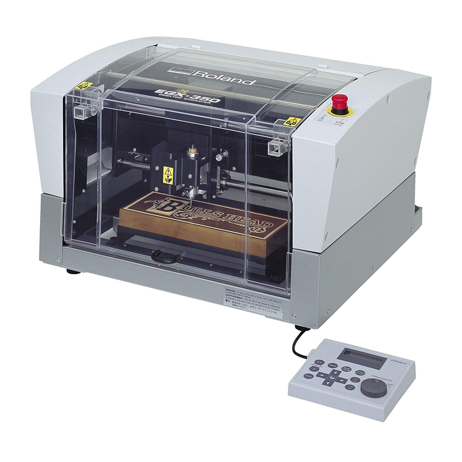
Page 25: Part Names And Functions
1-2 Part Names and Functions Front and Interior Spindle head * Lock lever This locks or unlocks the spindle head. P. 82, "The Position of the Lock Lever" Front cover To ensure safety, opening this during engraving or spindle rotation causes an emergency stop to Spindle unit occur. -
Page 26: Side
1-2 Part Names and Functions Side Right side Power switch Power-cord connector Left side Expansion port This is a connector for external equipment. P. 111, “Expansion Connector” Serial connector This is for connecting a serial (RS-232C- compliant) cable. P. 32, “Connecting a Computer Via a Com- munication Cable”... -
Page 27: Chapter 2 Installation And Setup
Chapter 2 Installation and Setup... -
Page 28: Checking The Included Items
Collet Collet (diameter 3.175 mm) (diameter 4.36 mm)*1,*2 Hexagonal screwdriver Handy panel Software guide (Roland Software Package) (Roland Engrave Studio) Adhesive sheet Vacuum-adapter set User’s Manual Roland Engrave Studio Roland Software Package CD-ROM CD-ROM *1: This is for diameter-4.36 mm character or flat cutters. -
Page 29: Installation
2-2 Installation About Emplacement and Installation WARNING Unloading and emplacement are operations that must be performed by 2 persons or more. Tasks that require undue effort when performed by a small number of persons may result in physical injury. Also, if dropped, such items may cause injury. The weight of the machine alone is 34 kg (75 lb.). - Page 30 2-2 Installation Installation Space Ensure that at least the following amount of space is available. Work space Installation space 1.0 m (3.3 ft.) 2.0 m (6.6 ft.) Height of Installation The height of installation should be 0.6 m (23.7 in.) or higher above the work floor. This machine is desktop type.
-
Page 31: Unpacking
2-2 Installation Unpacking Retaining materials are attached to protect the machine from vibration during shipment. Remove these after emplace- ment. ➢ Remove all Retaining materials. Any that remain may cause faulty operation or breakdown when the power is switched on. ➢... -
Page 32: Cable Connections
2-3 Cable Connections Connecting the Handy Panel Make sure the power to the machine is switched off before attempting to connect or disconnect cables. Connecting the handy panel while the power is on makes the handy panel unusable. Left side Insert fully and securely. -
Page 33: Connecting The Power Cord
2-3 Cable Connections Connecting the Power Cord Connect to an electrical outlet that complies with this machine's ratings (for volt- WARNING age and frequency). Incorrect voltage or insufficient current may cause fire or electrical shock. WARNING Handle the power cord, plug, and electrical outlet correctly and with care. Never use any article that is damaged. -
Page 34: Connecting A Computer Via A Communication Cable
USB cable At this time, keep the cable unconnected until you carry out this operation. Follow the instructions in the separate Roland Software Package Software Guide to make the connection. P. 19, "About the Documentation for This Machine" ➢Never connect two or more machines to one computer. -
Page 35: Selecting The Language
2-4 Selecting the Language Selecting the Language Used for Text on the Display Screen Procedure – Close the front cover. — Hold down and turn on the power switch. ˜ ➀ to select the language. ➁ Press to confirm. ➀ ➁... - Page 36 2-4 Selecting the Language ™ Switch off the power switch. Chapter 2 Installation and Setup...
-
Page 37: Before Starting Operations
2-5 Before Starting Operations Spindle Run-in (Warm-up) In any of the following cases, perform run-in (warm-up) operation for the spindle. Failure to do so may result in unstable spindle rotation. ➢ When using for the first time after purchase ➢ After moving the machine and reinstalling it at a different location ➢... -
Page 39: Chapter 3 Basic Operation
Chapter 3 Basic Operation... -
Page 40: Types Of Emergency Stops To Ensure Safety
3-1 Types of Emergency Stops to Ensure Safety How to Perform an Emergency Stop Press the Emergency Stop button. Operation stops immediately. Emergency Stop button To Cancel an Emergency Stop Procedure – Switch off the power switch. — Turn the button in the direction of the arrows. -
Page 41: Emergency Stop Due To Opening Or Closing The Front Cover
3-1 Types of Emergency Stops to Ensure Safety Emergency Stop Due to Opening or Closing the Front Cover To ensure safety, opening the front cover during engraving or spindle rotation causes an emergency stop to occur, and the message shown below appears on the display screen. Operation cannot be resumed by closing the front cover. To resume, switch off the power, then start up again. -
Page 42: Starting And Quitting
3-2 Starting and Quitting How to Start the Machine Follow the procedure below to start the machine. When startup is complete, the machine is ready for use. Procedure – Close the front cover. — Switch on the power switch. A message like the one shown in the figure appears on the handy panel’s display screen. -
Page 43: Shutdown
3-2 Starting and Quitting ˜ When the screen shown in the figure at left appears after approximately three seconds, press The spindle head moves to a location on the inner-left side of the machine. This operation is called “initialization.” The default for the language used for on-screen display is English. To change the display language to Japanese, refer to the page indi- cated below and change the language setting. -
Page 44: Using The Handy Panel
3-3 Using the Handy Panel Display screen Menus, messages, and the like are displayed here. Dial This adjusts the spindle’s speed of rotation. Indication used in this manual: P. 48, "Adjusting the Spindle Speed" MENU Button Copy button Pressing this changes the menu screen. Also, This calls up the menu for the copy feature. -
Page 45: Moving The Cutter
3-4 Moving the Cutter Terms Indicating the Cutter Position This manual uses the following terms to indicate the position of the cutter. ➢ Coordinates Numerical values indicating the location of the cutter ➢ Origin The point of origin for the coordinates ➢... -
Page 46: Manual Movement
3-4 Moving the Cutter Manual Movement When the screen on the handy panel displays any one of the messages shown in the figure below, you can move the cutter manually using the movement buttons. P. 84, "Menu List" Handy panel Movement along all axes (X, Y, and Z) Movement along only the X... -
Page 47: Moving To A Specific Position Automatically
3-4 Moving the Cutter Moving to a Specific Position Automatically Procedure – Close the front cover. — At the main screen, press twice. ˜ Press , or to select the move- ment destination. ➢ HOME This is the location where the X- and Y-axis coordinates are both “0”... - Page 48 3-4 Moving the Cutter ™ Press The cutter moves to the selected location. When the front cover is open, the screen shown in the figure below is displayed, and the cutter doesn’t move. After three seconds the message disappears and the screen returns to the original menu. Chapter 3 Basic Operation...
-
Page 49: Spindle Operation
3-5 Spindle Operation Starting and Stopping Spindle Rotation This manually starts and stops rotation of the spindle. You perform the operation using the handy panel. P. 35, "Spindle Run-in (Warm-up)" Procedure – Close the front cover. — At the main screen, press and hold for one second or longer. -
Page 50: Adjusting The Spindle Speed
3-5 Spindle Operation Adjusting the Spindle Speed To adjust the speed of spindle rotation, turn on the handy panel. The setting for the spindle speed can be made only on the machine. Any setting made on the computer is ig- nored. -
Page 51: Pausing And Stopping Cutting
3-6 Pausing and Stopping Cutting Pausing and Resuming Cutting This pauses cutting through operation using the handy panel. This enables you to move the cutter to the VIEW position and check the status of the workpiece, then resume cutting at the location where you paused operation. Procedure –... -
Page 52: Stopping Cutting
3-6 Pausing and Stopping Cutting Important! Before opening the front cover while operation is paused, first make sure that rotation of the spindle is stopped. For safety, opening the front cover while the spindle is turning makes the machine perform an emergency stop. Be sure to note that if this happens, it’s necessary to quit the operation and start over from the beginning. -
Page 53: Chapter 4 Engraving
Chapter 4 Engraving... -
Page 54: Flow Of Engraving Operations
4-1 Flow of Engraving Operations Startup Switch on the power switch to start the machine. P. 40, “How to Start the Machine” Mounting the Workpiece Mount the workpiece to engrave on the table. P. 54, “Mounting a Workpiece” To next page Chapter 4 Engraving... -
Page 55: Setting The Xy Origin Point
4-1 Flow of Engraving Operations Cutter Installation and Basic Engraving Settings Install the cutter to use for engraving. On this machine, you also set the Z-axis engraving origin point at this time. The methods you use for installation and the settings differ depending on whether you’re using the nose unit and on the cutter type. -
Page 56: Mounting A Workpiece
Adhensive sheet On this machine, you can also use optionally available items to secure the workpiece in place: a center vise (ZV-23C) or a vacuum table (ZV-23A). For detailed information about these optional items, contact your authorized Roland DG Corp. dealer. -
Page 57: Selection Of The Cutter (Usage Examples)
Use an appropriate collet for the cutter’s diameter and type. For other cutters that can be used with the machine, contact your authorized Roland DG Corp. dealer. The table below shows samples of cutter usage, including use with or without a nose unit. -
Page 58: Cutter Installation Method 1 (With Nose Unit)
4-4 Cutter Installation Method 1 (With Nose Unit) Installing a Character Cutter (With Nose Unit) WARNING Never inadvertently touch the computer or handy panel while performing this task. Unintended operation of the machine may result in injury. WARNING Securely fasten the cutting tool and in place. After securing in place, make sure no wrenches or other articles have inadvertently been left behind. - Page 59 4-4 Cutter Installation Method 1 (With Nose Unit) — Install the solid collet. ➀ ➀ Loosely tighten the solid collet. Insert the solid collet into the spindle unit Wrench from below, then, while holding the spindle unit immobile with a wrench, tighten loosely.
- Page 60 4-4 Cutter Installation Method 1 (With Nose Unit) Set the lock lever. Set the lock lever at the posi- tion. For detailed information about the setting position for the lock lever, refer to the page indicated below. Lock lever P. 82, “The Position of the Lock Lever” Press down to lower slightly.
- Page 61 4-4 Cutter Installation Method 1 (With Nose Unit) Install the cutter and make the setting for the cutting-in depth. – , and move the spindle head to the area above the workpiece, then press lower the spindle head. Descent stops automatically when the tip of the nose unit touches the workpiece table.
- Page 62 4-4 Cutter Installation Method 1 (With Nose Unit) ˜ Secure the cutter in place. Tighten the mounting screw for the cutter holder. Cutter holder Mounting screw Hexagonal screwdriver ™ Make the setting for the cutting-in depth. ➀ Tighten the nose unit to match the desired cutting-in depth.
-
Page 63: Important Notes When Using The Nose Unit
4-4 Cutter Installation Method 1 (With Nose Unit) Important Notes When Using the Nose Unit Amount of Height Displacement That Can Be Tracked When automatic Z control is set to “ON,” then as long as the tip of the nose unit is in contact with the surface of the workpiece, the cutting-in depth can be kept uniform even if the height of the material changes. -
Page 64: Cutter Installation Method 2 (No Nose Unit)
4-5 Cutter Installation Method 2 (No Nose Unit) Installing a Character Cutter (With No Nose Unit) WARNING Never inadvertently touch the computer or handy panel while performing this task. Unintended operation of the machine may result in injury. WARNING Securely fasten the cutting tool and in place. After securing in place, make sure no wrenches or other articles have inadvertently been left behind. - Page 65 4-5 Cutter Installation Method 2 (No Nose Unit) — Install the solid collet. ➀ ➀ Loosely tighten the solid collet. Insert the solid collet into the spindle unit Wrench from below, then, while holding the spindle unit immobile with a wrench, tighten loosely.
- Page 66 4-5 Cutter Installation Method 2 (No Nose Unit) Make the settings for spindle speed and Z-axis control. – Press several times to display the screen shown at left. to select [OTHERS]. Press — to select “ON.” Press to confirm. ˜ Press to select “OFF.”...
- Page 67 4-5 Cutter Installation Method 2 (No Nose Unit) If cutter insertion is difficult When using a diameter-4.36 mm solid collet If the cutter catches on the solid collet and is difficult to Be careful to orient the cutter correctly. insert, loosening the cutter holder makes insertion easier. Note that inserting it with undue force may result in damage to the workpiece.
- Page 68 4-5 Cutter Installation Method 2 (No Nose Unit) Storage methods for diameter-3.175 mm cutters When you want to perform repeated use while keeping the amount of extension of the cutter tip constant, then once you’ve decided on the amount of extension, we recommend removing the cutter holder and cutter from the spindle unit without separating them from one another.
-
Page 69: Cutter Installation Method 3 (Diamond Scraper)
4-6 Cutter Installation Method 3 (Diamond Scraper) Installing a Diamond Scraper WARNING Never inadvertently touch the computer or handy panel while performing this task. Unintended operation of the machine may result in injury. WARNING Securely fasten the cutting tool and in place. After securing in place, make sure no wrenches or other articles have inadvertently been left behind. - Page 70 4-6 Cutter Installation Method 3 (Diamond Scraper) — Install the solid collet. ➀ ➀ Loosely tighten the solid collet. Insert the solid collet into the spindle unit Wrench from below, then, while holding the spindle unit immobile with a wrench, tighten loosely.
- Page 71 4-6 Cutter Installation Method 3 (Diamond Scraper) Make the settings for spindle speed and Z-axis control. – Press several times to display the screen shown at left. to select [OTHERS]. Press — to select “OFF.” Press to confirm. ˜ Press to select “ON.”...
- Page 72 4-6 Cutter Installation Method 3 (Diamond Scraper) — Secure the diamond scraper in place. Tighten the mounting screw for the cutter Cutter holder holder. For the amount of extension of the tip Hexagonal of the diamond scraper, a value of about 10 screwdriver millimeters may work well.
-
Page 73: Cutter Installation Method 4 (End Mill)
4-7 Cutter Installation Method 4 (End mill) Installing a End Mill WARNING Never inadvertently touch the computer or handy panel while performing this task. Unintended operation of the machine may result in injury. WARNING Securely fasten the cutting tool and in place. After securing in place, make sure no wrenches or other articles have inadvertently been left behind. - Page 74 4-7 Cutter Installation Method 4 (End mill) — Install the collet with the attached end ➀ mill. ➀ Loosely tighten the collet with end Wrench mill. Insert the collet with end mill into the spindle unit from below, then, while hold- ing the spindle unit immobile with a wrench, tighten loosely.
- Page 75 4-7 Cutter Installation Method 4 (End mill) Make the settings for spindle speed and Z-axis control. – Press several times to display the screen shown at left. to select [OTHERS]. Press — to select "ON." Press to confirm. ˜ Press to select "OFF."...
- Page 76 4-7 Cutter Installation Method 4 (End mill) š Press › to select [Z0]. œ Press to confirm. The Z-axis origin point is set. Press The main display appears. The coordinate values for Z is set to 0. This completes the installation of the end mill. Go on to page 75, “Setting the XY Origin Point (Home Position)." Chapter 4 Engraving...
-
Page 77: Setting The Xy Origin Point
4-8 Setting the XY Origin Point Setting the XY Origin Point (Home Position) This sets the X- and Y-axis coordinates used as the origin point for cutting. This location is termed the XY origin point, which on this machine is called the “home position.” On this machine, you can set the XY origin anywhere within the operating range. -
Page 78: Performing Engraving
4-9 Performing Engraving Performing Engraving Make sure the following tasks have all been completed, then sent the engraving data from the computer and perform engraving. ➢ Mounting a Workpiece P. 54, “Mounting a Workpiece” ➢ Cutter Installation P. 56 through 71, “Cutter Installation Method 1” through “Cutter Installation Method 4” ➢... -
Page 79: Adjusting The Cutter Feed Rate During Engraving (Override)
4-9 Performing Engraving Adjusting the Cutter Feed Rate During Engraving (Override) While engraving is in progress, you can pause operation and adjust the feed rate for the cutter. You adjust the feed rate by specifying a ratio of change relative to the present feed rate. This feature is called “override.” The feed rate can be adjusted only within the machine’s settable feed-rate range. -
Page 80: Executing Repeated Cutting
4-9 Performing Engraving Executing Repeated Cutting A single set of cutting data is saved in the machine’s memory until the next set of data is sent from the computer. You can use this data to repeat the same cutting by operating just the machine. Note, however, that cutting data that exceeds the machine’s memory capacity (2 MB) cannot be copied. -
Page 81: Chapter 5 Feature Reference
Chapter 5 Feature reference... -
Page 82: Attaching The Vacuum Adapter For Chip Cleaning
5-1 Attaching the Vacuum Adapter for Chip Cleaning WARNING Exercise caution to prevent fire or dust explosion. Taking up fine cuttings using an ordinary vacuum cleaner may cause danger of fire or explosion. Check with the manufacturer of the vacuum cleaner. When the safety of use cannot be determined, never use the vacuum adapter and a vacuum cleaner. - Page 83 5-1 Attaching the Vacuum Adapter for Chip Cleaning Move the spindle head to the front left of the workpiece table, then attach the vacuum adapter for chip cleaning as shown in the figure. Using the vacuum adapter for chip cleaning enables the vacuum cleaner to take up cutting waste during cutting, which can help keep scattering of cutting waste to a minimum.
-
Page 84: The Position Of The Lock Lever
5-2 The Position of the Lock Lever You change the position at which the lock lever is set to match the setting for automatic Z control. P. 56 through 71, “Cutter Installation Method 1” through “Cutter Installation Method 4,” and p. 85, “Submenus” Setting Position of the Lock Lever ➣... -
Page 85: Surface Leveling Of The Workpiece Table
5-3 Surface Leveling of the Workpiece Table This adjusts the flatness of the surface of the workpiece table by cutting the table surface to a uniform depth. This operation is called “surface leveling” or “surfacing.” This can be useful in cases where rigorously precise flatness is required, such as for plate engraving performed without using the nose unit. -
Page 86: Menu List
5-4 Menu List Main Menu P. 88, “Main Menu” (Descriptions of Menu Items) Chapter 5 Feature reference... -
Page 87: Submenus
5-4 Menu List Submenus P. 91, "Adjustment Menu" P. 89, "I/O Menu" P. 90, "Others Menu" Chapter 5 Feature reference... -
Page 88: Origin-Setting Menu
5-4 Menu List Origin-setting Menu P. 92, "Origin-setting Menu" (Descriptions of Menu Items) Pause Menu P. 93, "Pause Menu" (Descriptions of Menu Items) Chapter 5 Feature reference... -
Page 89: Copy Menu
5-4 Menu List Copy Menu P. 93, "Copy Menu" (Descriptions of Menu Items) Chapter 5 Feature reference... -
Page 90: Description Of Menu Items
5-5 Description of Menu Items Main Menu P. 84, "Main Menu" (Menu List) This is the main screen. This screen is displayed at startup and when executing cutting. When [AUTO Z CONTROL] is set to “ON,” the Z-axis coordinate display changes to “AUTO.”... -
Page 91: I/O Menu (Submenu)
5-5 Description of Menu Items I/O Menu (Submenu) This selects the communication port for communication with the computer and makes the settings for the communi- cation parameters when using a serial connection. When you’re using a USB connection, simply selecting the com- munication port completes the settings you have to make. -
Page 92: Others Menu (Submenu)
5-5 Description of Menu Items Others Menu (Submenu) P. 85, "Submenus" This determines whether the spindle is rotated during cutting. When this is set to “OFF,” scribing (cutting without rotation of the spindle) is performed. ➢ Default setting: ON Set this to “ON” in cases such as when you’re using the nose unit. Setting this to “ON”... -
Page 93: Adjustment Menu (Submenu)
5-5 Description of Menu Items This selects whether the Z0, Z1, and Z2 locations are saved in memory on the machine. ➢ Default setting: ON P. 78,"Executing Repeated Cutting," p.92,"Origin-setting Menu" This displays the working time of the spindle motor. Use it as a guide for deter- mining the service life of the spindle unit. -
Page 94: Origin-Setting Menu
5-5 Description of Menu Items Origin-setting Menu P. 86, "Origin-setting Menu" XY Origin-setting Menu This makes the setting for the X- and Y-axis origin point. On this machine, this location is called the “home position.” P. 75, "Setting the XY Origin Point (Home Position)" Z Origin-setting Menu Before making these settings, make sure of the following points. -
Page 95: Pause Menu
5-5 Description of Menu Items Pause Menu P. 86, "Pause Menu" Pressing while a cutting operation is in progress pauses cutting and displays the screen shown in the figure at left. You can select an operation such as resuming or quitting cutting. P. -
Page 97: Chapter 6 Maintenance
Chapter 6 Maintenance... -
Page 98: Daily Care
6-1 Daily Care Cleaning WARNING Never use a pneumatic blower. This machine is not compatible with a pneumatic blower. Cutting waste may get inside the machine and cause fire or electrical shock. WARNING Never use a solvent such as gasoline, alcohol, or thinner to perform cleaning. Doing so may cause fire. -
Page 99: Cleaning Around The Spindle
6-1 Daily Care Cleaning Around the Spindle Cleaning the Spindle Nose Uninstall the nose unit, collet, and cutter, and remove any cutting waste that has collected in areas such as the spindle nose. Spindle unit Cleaning Inside the Spindle Unit Cover Detach the spindle unit cover and clean away any buildup of cutting waste inside. -
Page 100: Maintenance And Inspection
6-2 Maintenance and Inspection Spindle Maintenance The spindle unit and the belt are parts that wear out. The replacement cycle varies according to usage conditions, but as a general guide, you should replace them after every 2,000 hours of use. This machine is provided with a feature for displaying the total working time of the spindle unit. -
Page 101: Chapter 7 Troubleshooting
Chapter 7 Troubleshooting... -
Page 102: Troubleshooting (Engraving)
7-1 Troubleshooting (Engraving) The cutting-in depth is not uniform (when using the nose unit). The cutter leaves tracks at places where cutting-in starts or where lines change direction. Try revising the cutting parameters as described below. ➢ Is automatic Z control set to"ON" with the lock lever at position P. -
Page 103: Troubleshooting (Operation)
Cancel the emergency stop. using the correct procedure. P. 38, “To Cancel an Emergency Stop” "Roland Software Package Software Guide" Are the parameter settings for communication with Initialization is not performed or initialization fails the computer correct? The machine cannot communicate with the computer if the Isn’t the cover open? -
Page 104: The Usb Cable Came Loose During Engraving
7-2 Troubleshooting (Operation) The USB cable came loose during engraving. If the machine succeeded in receiving all the engraving data, the engraving is carried out to the end of the operation. If the machine did not receive all the engraving data, engraving is carried out for the portion received, and then the cutter rises and stops at a location away from the workpiece. -
Page 105: Responding To A Message
7-3 Responding to a Message These are the most common messages that appear on the [Turn the AUTO Z CONTROL off] machine’s display to prompt correct operation. They do not indicate any error. Follow the prompts and take action This was displayed because an attempt was made to set the accordingly. -
Page 106: Responding To An Error Message
An emergency stop occurred because initialization correct the problem, or if an error message not described failed. here appears, contact your authorized Roland DG Corp. Switch the power off, remove any cutting waste or other ob- dealer. structions impeding operation of the spindle head, then redo the operation from the start. - Page 107 Eliminate the causes, then redo the operation from the beginning. If this message continues to appear, contact your authorized Roland DG Corp. dealer. P. 40, "Starting and Quitting," p. 50, "Stopping Cutting"...
-
Page 109: Chapter 8 Appendix
Chapter 8 Appendix... -
Page 110: Examples Of Settings For Cutting Parameters
8-1 Examples of Settings for Cutting Parameters Example Settings This machine lets you perform cutting using a wide variety of workpiece materials and cutters. However, the optimal cutting parameters that yield the desired cutting results for these combinations vary widely. The table below shows suggested cutters and cutting parameters suited to various types of workpieces. -
Page 111: Location Of Power Rating And Serial Number Label
8-2 Location of Power Rating and Serial Number Label Serial Number This is required when you seek maintenance or support. Never peel off. Power Rating Use an electrical outlet that meets the re- quirements for voltage, frequency, and ca- pacity given here. Chapter 8 Appendix... -
Page 112: Interface Specifications
8-3 Interface Specifications Serial Connector Standard RS-232C specification Transmission method Asynchronous, duplex data transmission Transmission speed 4800, 9600, 19200, 38400 Parity check Odd, Even, None Data bits 7 or 8 bits Stop bits 1 or 2 bits Handshake Hardware or Xon/Xoff Serial connector (RS-232C) XY-RS-34/14 cable connection Signal... -
Page 113: Expansion Connector
8-2 Interface Specifications Expansion Connector +24 V Adaptive Plug Pin 1 Connec- Pin 2 Use a three-contact plug that meets the size requirements above. Ic (max) = 150mA Do not use the terminal 3. Use only This circuit works during spindle motor rotation. the 1 and 2 terminals. -
Page 114: Main Unit Specification
8-4 Main Unit Specification Dimensions of Outline Unit: mm Chapter 8 Appendix... -
Page 115: Work Area
8-4 Main Unit Specification Work area XY work area Unit: mm Z work area Note: Maximum workpiece thickness when the nose unit is used is 38 mm. Note: The area in which engraving can actually be performed (the engraving area) is restricted by the length of the installed cutter and the location where the nose unit is installed, and is smaller than the range indicated above. -
Page 116: Workpiece-Table Installation-Area Dimensional Drawing
8-4 Main Unit Specification Workpiece-table Installation-area Dimensional Drawing Unit: mm Chapter 8 Appendix... -
Page 117: Main Specifications
3.175 mm), flat cutter (diameter 3.175 mm), wrench, solid collet (diameter 3.175 mm), solid collet (diameter 4.36 mm), hexagonal wrench, hexagonal screwdriver, handy panel, adhesive sheet, vacuum adapter for chip cleaning, Roland Software Package CD-ROM, Roland EngraveStudio CD-ROM, Roland Software Package Pro- gram Guide, Roland EngraveStudio Program Guide, and User’s Manual (this docu-... - Page 124 R1-070626...