Table of Contents
Advertisement
Quick Links
Integrated 12 Channel WAAS GPS receiver
GPS antenna built-in to the front panel allows reception when bracket or flush
mounted
Ultra thin and compact rear case design (3.5" depth)
Meets ITU-R M493-13 Class D DSC (Digital Selective Calling)
Navigation to a DSC Distress Call with compass page
DSC test call and Auto DSC channel change selection
Automatically poll the GPS position of up to 4 ships using DSC
Enter, Save, and Navigation to a waypoint with Compass page
Navigation (LAT/LON, SOG, and COG) information shown on display
Submersible JIS-8 1.5M (4.92Ft) for 30 minutes
Noise canceling microphone with channel selection, 16/9 and H/L keys
NOAA weather channel selection with alert
Programmable Scan, Priority Scan, and Dual Watch
Preset key stores up to 10 favorite channels, with scan function
Oversized dot matrix display with customizable channel names and GPS Com-
pass display
NMEA Input and Output of GPS information to other NMEA compatible devices
Programmable soft keys
Capable of connecting to a Second Station Remote-Access Microphone
CMP30
Die-cast chassis
Dimensions: 5.9" W x 3.4" H x 3.6" D
Flush mount cutout: 5.4" W x 2.8" H x 2.6" D
3 Year Waterproof Warranty
GX1700
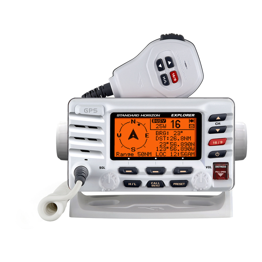
EXPLORER GPS GX1700
25 Watt VHF/FM
Marine Transceiver
Owner's Manual
Page 1
Advertisement
Table of Contents

Related Manuals for Standard Horizon Explorer GPS GX1700


Summary of Contents for Standard Horizon Explorer GPS GX1700
- Page 1 EXPLORER GPS GX1700 25 Watt VHF/FM Marine Transceiver Owner's Manual Integrated 12 Channel WAAS GPS receiver GPS antenna built-in to the front panel allows reception when bracket or flush mounted Ultra thin and compact rear case design (3.5” depth) ...
-
Page 2: Table Of Contents
TABLE OF CONTENTS 8.10 PRESET CHANNELS ( 0 ~ 9 ) : INSTANT ACCESS ....34 Quick Reference Guide ................4 1 GENERAL INFORMATION ..............5 8.10.1 Preset Channel Programming ........34 2 PACKING LIST ..................5 8.10.2 Operation ...............34 3 OPTIONS ....................5 8.10.3 Deleting a Preset Channel ...........34 4 ON-LINE WARRANTY REGISTRATION ( in USA or Canada only ) ...6 8.11 INTERCOM OPERATION . - Page 3 TABLE OF CONTENTS 9.8 POSITION REQUEST ..............58 12 DSC SETUP ..................82 9.8.1 Position Reply Setup ...........58 12.1 INDIVIDUAL DIRECTORY ............82 9.8.2 Position Request Ringer Setup ........59 12.2 INDIVIDUAL REPLY ..............82 9.8.3 Transmitting a Position Request 12.3 INDIVIDUAL ACKNOWLEDGMENT .........82 to Another Vessel ............59 12.4 INDIVIDUAL RINGER ...............82 9.8.3.1 Position Request 12.5 GROUP DIRECTORY ...............82 using the Individual Directory ......59 12.6 POSITION REPLY ..............83 9.8.3.2 Position Request 12.7 AUTO POSITION INTERVAL .
-
Page 4: Quick Reference Guide
uick efeRence uide This transceiver is equipped with the E2O (Easy-To-Operate) system. You can do the basic operation in numerical order in the illustration below. Press and hold the button to turn on or off the radio. Rotate the SQL knob counter clockwise to unsquelch the radio. ... -
Page 5: General Information
1 GENERAL INFORMATION The STANDARD HORIZON EXPLOPER GPS GX1700 Marine VHF/FM Ma- rine transceiver is capable of ITU-R 493-13 DSC (Digital Selective Calling) Class D operation with a 12 channel internal GPS. Class D operation allows continuous receiving of Digital Selective Calling functions on channel 70 even if the radio is receiving a call. -
Page 6: On-Line Warranty Registration (In Usa Or Canada Only)
4 ON-LINE WARRANTY REGISTRATION (in USA or Canada only) Please visit www.standardhorizon.com to register the GX1700 Marine VHF. It should be noted that visiting the Web site from time to time may be beneficial to you, as new products are released they will appear on the STANDARD HORIZON Web site. -
Page 7: Getting Started
5 GETTING STARTED PROHIBITED COMMUNICATIONS The FCC prohibits the following communications: • False distress or emergency messages: • Messages to “any boat” except in emergencies and radio tests; • Messages to or from a vessel on land; • Transmission while on land; •... -
Page 8: Coaxial Cable
5.3.1 Coaxial Cable VHF antennas are connected to the transceiver by means of a coaxial cable – a shielded transmission line. Coaxial cable is specified by it’s diameter and construction. For runs less than 20 feet, RG-58/U, about 1/4 inch in diameter is a good choice. -
Page 9: Calling Another Vessel (Channel 16 Or 9)
7. Estimate the present seaworthiness and condition of your vessel. 8. Give your vessel’s description: length, design (power or sail), color and other distinguishing marks. The total transmission should not exceed 1 minute. 9. End the message by saying “OVER”. Release the microphone button and listen. -
Page 10: Operating On Channels 13 And 67
the PTT button on the mic. Then switch to the new channel. When the new channel is not busy, call the other vessel. After a transmission, say “over,” and release the microphone’s push-to-talk (PTT) switch. When all communication with the other vessel is completed, end the last transmission by stating your Call Sign and the word “out.”... - Page 11 The Automated Radio Check Service is currently available in the areas listed below. West Coast South Carolina Newport/LA - Ch. 27 Charleston - Ch. 27 San Diego - Ch. 27 Georgetown - Ch. 27 Northeast Myrtle Beach - Ch. 27 Central Connecticut - Ch.
-
Page 12: Installation
6 INSTALLATION SAFETY / WARNING INFORMATION This radio is restricted to occupational use, work related operations only where the radio operator must have the knowledge to control the exposure conditions of its passengers and bystanders by maintaining the minimum separation distance of 0.89 m (2.92 feet). Failure to observe these restric- tions will result in exceeding the FCC RF exposure limits. -
Page 13: Optional Mmb-97 Flush Mount Bracket
GPS location on it’s display. If the radio is not able to receive a location, a GPS Chart plotter with NMEA 0183 output or the optional Standard Horizon external GPS antenna may be needed to receive GPS satellite signals. -
Page 14: Electrical Connections
ELECTRICAL CONNECTIONS CAUTION Reverse polarity battery connections will damage the radio! Connect the power cord and antenna to the radio. Antenna and Power Sup- ply connections are as follows: 1. Mount the antenna at least 3 feet (1 m) away from the radio. At the rear of the radio, connect the antenna cable. -
Page 15: Accessory Cable
Fix. The GX1700 Internal GPS must be turned off (refer to section “14.9 UNIT POWER”) and the GPS Selection must be selected to External GPS (refer to section “14.9 GPS SELECTION”). 6.5.2.1 GPS Input - Standard Horizon GPS Antenna Standard Horizon GPS Antenna... -
Page 16: Gps Input And Dsc Output Gps Chart Plotter (Rs422 Connection)
Brown: NMEA DSC Output ( ) NMEA Input ( ) White External Speaker Shield 6.5.2.3 Standard Horizopn GPS Chart Plotter or Other Chart Plotter (RS232 Connections) Standard Horizon Chart Plotter Plotter Radio Wires Connection Blue: NMEA GPS Input ( ) Brown: NMEA Output ( ) -
Page 17: Checking Gps Status
• The NMEA 0183 input sentences are GLL, GGA, RMC and GNS (RMC sentence is recommended). NMEA Output (DSC) The NMEA 0183 output sentences are DSC and DSE. If you have further inquires, please feel free to contact Product Support at: Phone: (800) 767-2450 Email: marinetech@vxstdusa.com CHECKING GPS STATUS... -
Page 18: Changing The Gps Time
CHANGING THE GPS TIME From the Factory the GX1700 shows GPS satellite time or UTC (Universal Time Coordinated or GPS Satellite Time). A time offset is needed to show the local time in your area. Please see the Offset Time Table at the bottom of this page. -
Page 19: Changing The Time Area
CHANGING THE TIME AREA This menu selection allows the radio to show UTC (Universal Time Coordi- nated or GPS Satellite Time) or local time with the offset. 1. Press and hold down the key until “ Setup -Setup Menu- GENERAL SETUP Menu ”... -
Page 20: Changing Cog To True Or Magnetic
6.10 CHANGING COG TO TRUE OR MAGNETIC Allows the GPS Course Over Ground to be selected to show in True or Mag- netic. Factory default is True however by following the steps below the COG can be changed to Magnetic. 1. - Page 21 5. Referring to illustration below, make a 1.2” (30 mm) hole in the wall, then insert the Extension Cable into this hole. Connect the Gasket and Mount Base to the Extension Cable Connector using the Nut. 6. Drill the four Screw holes (approx. 2 mm) on the wall, then install the Mounting Base to the wall using four screws.
-
Page 22: Connecting An External Speaker To The Ram3 Mic Cable
6.11.1 Connecting an External Speaker to the RAM3 Mic Cable In noisy locations and optional external speaker may be connected to the white speaker wires on the RAM3 routing cable (refer to previous page). The RAM3 can drive the internal speaker or the external speaker one at a time. When connecting an external speaker, follow the procedure below to turn off the RAM3 audio and enable the external speaker wires on the RAM3 routing cable. - Page 23 MEMO _ _ _ _ _ _ _ _ _ _ _ _ _ _ _ _ _ _ _ _ _ _ _ _ _ _ _ _ _ _ _ _ _ _ _ _ _ _ _ _ _ _ _ _ _ _ _ _ _ _ _ _ _ _ _ _ _ _ _ _ _ _ _ _ _ _ _ _ _ _ _ _ _ _ _ _ _ _ _ _ _ _ _ _ _ _ _ _ _ _ _ _ _ _ _ _ _ _ _ _ _ _ _ _ _ _ _ _ _ _ _ _ _ _ _ _ _ _ _ _ _ _ _ _ _ _ _ _ _ _ _ _ _ _ _ _ _ _ _ _ _ _ _ _ _ _ _ _ _ _ _ _ _ _ _ _ _ _ _ _ _ _ _ _ _ _ _ _ _ _...
-
Page 24: Controls And Indicators
7 CONTROLS AND INDICATORS NOTE This section defines each control of the transceiver. For operating in- structions refer to section “8 BASIC OPERATION”. FRONT PANEL keys are used to select channels and to choose menu items (such as the DSC menu, Radio Setup and DSC Setup menu). keys on the microphone can also be used to select channels and menu items. - Page 25 Used to send a DSC Distress Alert. To transmit a Distress Alert refer to section “9.2.2 Programming the MMSI” and “9.3.1 Transmitting a DSC Distress Alert”. VOL Knob ( Volume Control Knob ) Adjusts the audio volume level. Turn this knob clockwise to increase the audio volume level.
-
Page 26: Rear Panel
External Speaker Connection Cable ( White & Shield ) Connects the GX1700 to an external speaker. See section “3 OPTIONS” for a list of optional STANDARD HORIZON Speakers. GND Terminal ( Ground Terminal ) Connecting a Ground wire to this connection will help reduce engine noise when receiving and transmitting. -
Page 27: Microphone
MICROPHONE PTT ( Push-To-Talk ) Switch When in radio mode and the PTT switch pressed, the transmitter is enabled for voice communications to another vessel. When a optional RAM3 second station microphone is connected and intercom mode is selected, pressing the PTT switch enables voice communications from the GX1700 to the RAM3 second sta- tion microphone. -
Page 28: Basic Operation
8 BASIC OPERATION RECEPTION 1. After the transceiver has been installed, ensure that the power supply and antenna are properly connected. 2. Press and hold the key until the radio turns on. 3. Rotate the SQL knob fully counterclockwise until “ ”... -
Page 29: Simplex/Duplex Channel Use
SIMPLEX/DUPLEX CHANNEL USE Refer to section “17 CHANNEL ASSIGNMENTS” for instructions on use of simplex and duplex channels. NOTE All channels are factory-programmed in accordance with FCC (USA), Industry Canada, and International regulations. Mode of operation cannot be altered from simplex to duplex or vice-versa. DISPLAY TYPE The GX1700 display can be setup to show displays other than the default “NORMAL”... -
Page 30: Usa, Canada, And International Mode
USA, CANADA, AND INTERNATIONAL MODE To change the channel group from USA to Canada or International: 1. Press and hold down the key until “ Set- -Setup Menu- GENERAL SETUP up Menu ” appears. CH Function Setup DSC Setup Waypoint Setup 2. -
Page 31: Noaa Weather Testing
NOTE If a key is not pressed the alert will sound for 5 minutes and then the weather report will be received. While listening to a weather channel, the radio can decode a weather alert and sound an alarm. 8.7.2 NOAA Weather Alert Testing NOAA tests the alert system ever Wednesday between 11AM and 1PM. -
Page 32: Scanning
SCANNING Allows the user to select the scan type from Memory scan or Priority scan. “Memory scan” scans the channels that were programmed into memory. “Priority scan” scans the channels programmed in memory with the priority channel. 8.9.1 Scan Type Selection 1. -
Page 33: Memory Scanning ( M-Scan )
channel. 6. Repeat step 5 for all the desired channels to be scanned. 7. To DELETE a channel from the list, select the channel then press the soft key. “MEM” icon disappears from the display. 8. When you have completed your selection, press the soft key sev- eral times to return to radio operation. -
Page 34: Preset Channels ( 0 ~ 9 ) : Instant Access
8.10 PRESET CHANNELS ( 0 ~ 9 ) : INSTANT ACCESS 10 Preset Channels can be programmed for instant access. Pressing the key activates the preset channel bank. If the key is pressed and no channels have been assigned, an alert beep will be emitted from the speaker. -
Page 35: Intercom Operation
8.11 INTERCOM OPERATION An optional RAM3 ( CMP30 ) must be connected to perform intercom func- tions between the radio and the RAM3 ( CMP30 ) . In addition, To access the following Intercom functions one of the soft keys must be setup as . -
Page 36: Digital Selective Calling
9 DIGITAL SELECTIVE CALLING GENERAL WARNING This radio is designed to generate a digital maritime distress and safety call to facilitate search and rescue. To be effective as a safety device, this equipment must be used only within communication range of a shore-based VHF marine channel 70 distress and safety watch system. -
Page 37: Programming The Mmsi
How can I obtain an MMSI assignment? In the USA, visit the following websites to register: http://www.boatus.com/mmsi/ or http://seatow.com/boating_safety/mmsi.asp In the Canada, visit http://www.ic.gc.ca/epic/site/smt-gst.nsf/en/sf01032e.html or http://www.usps.org/php/mmsi/rules.php 9.2.2 Programming the MMSI WARNING A user MMSI can be inputted only once. Therefore please be careful not to input the incorrect MMSI number. -
Page 38: Dsc Distress Alert
NOTE To view your MMSI after programming to ensure it is correct, perform steps 1~3. Look that the MMSI number shown on the display is correct. DSC DISTRESS ALERT The GX1700 is capable of transmitting and receiving DSC Distress mes- sages with your vessels position. -
Page 39: Transmitting A Dsc Distress Alert With Nature Of Distress
9.3.1.1 Transmitting a DSC Distress Alert with Nature of Distress The GX1700 is capable of transmitting a DSC Distress Alert with the follow- ing “Nature of Distress” categories you may have: Undesignated, Fire, Flooding, Collision, Grounding, Capsizing, Sinking, Adrift, Abandoning, Piracy, MOB 1. -
Page 40: Transmitting A Dsc Distress Alert By Manually Entering A Position
9.3.1.2 Transmitting a DSC Distress Alert by Manually Entering a Position The GX1700 allows you to manually enter a latitude/Longitude of your vessel to be able to transmit a DSC Distress alert. 1. Lift the red spring loaded DISTRESS cover and !DISTRESS ALERT! Nature of:Undesignated press the... -
Page 41: Pausing A Dsc Distress Call
9.3.1.3 Pausing a DSC Distress Call After a DSC Distress call is transmitted, the DSC distress call is repeated every 4 minutes until the call is canceled by the user or until the radio is turned on and off again. The GX1700 has provision to suspend (Pause) the retransmitting of the distress call by the procedure below. - Page 42 the letter/number by pressing the Received DISTRESS WPT Name: and move the cursor by pressing the DIST ID:XXXXXXXXX Position: 33 39.220 soft key). 118 10.560 5. The ID is the MMSI from the vessel in distress. QUIT 6. When you are finished entering the waypoint name, press and hold the soft key to re- BRG:300...
-
Page 43: All Ships Call
ALL SHIPS CALL The All Ships Call function allows contact to be established with DSC equipped vessels without having their MMSI in the individual calling direc- tory. Also, priority for the call can be designated as Urgency or Safety. URGENCY Call: This type of call is used when a vessel may not truly be in distress, but have a potential problem that may lead to a distress situation. -
Page 44: Receiving An All Ships Call
9.4.2 Receiving an All Ships Call 1. When an all ships call is received, an emergency Received All Ships Name:Horizon alarm will sound. ID:123456789 Category:Safety The display shows the MMSI of the vessel trans- CH: 06 Since: 01:03 mitting the All Ships Call and the radio will change ACCEPT PAUSE QUIT... -
Page 45: Individual Call
INDIVIDUAL CALL This feature allows the GX1700 to contact another vessel with a DSC VHF radio and automatically switch the receiving radio to a desired communications channel. This feature is similar to calling a vessel on CH16 and requesting to go to another channel (switching to the channel is private between the two stations). -
Page 46: Individual Reply Setup
tity Number) number entry. -Individual Directory- 10. Press the key to scroll through num- Individual Name Horizon bers, 0-9. To enter the desired number and move ID:--------- one space to the right by pressing the soft BACK QUIT key. Repeat this procedure until all nine space of the MMSI number are entered. -
Page 47: Individual Acknowledgment Setup
9.5.3 Individual Acknowledgment Setup The GX1700 can select either reply message “Able” (default) or “Unable” when the Individual Reply setting (described previous section) is set to “AU- TOMATIC”. When the Individual Reply setting (described previous section) is set to “AUTOMATIC”, the GX1700 can be setup to reply “Able” (default) or not re- ply “Unable”... -
Page 48: Transmitting An Individual Call
The GX1700 has the capability to turn off the Individual and Group call ringer. 1. Press and hold down the key until “ Set- -Setup Menu- GENERAL SETUP up Menu ” appears. CH Function Setup DSC Setup 2. Press the key to select “... -
Page 49: Individual Call By Manually Entering A Mmsi
5. Press the soft key, then press the -Select Intership CH- key to select the operating chan- nel you want to communicate on, then press -Select Intership CH- soft key. If the channel is not SELECT MANUAL QUIT shown in the list, press the soft key, then press the key to select the oper-... -
Page 50: Receiving An Individual Call
lected, then press the key to correct the -Select Intership CH- entry. 8. When finished entering the MMSI number, press and hold the soft key. SELECT MANUAL QUIT 9. Press the key to select the operating -Select Intership CH- channel you want to communicate on, then press soft key. -
Page 51: Dsc Log Operation
DSC LOG OPERATION The GX1700 logs transmitted calls, received distress calls, and other calls (Individual, Group, All Ship etc.). The DSC Log feature is similar to an an- swer machine where calls are recorded for review and a “ ” icon will ap- pear on the radios display. -
Page 52: Reviewing A Other Logged Calls
icon will appear behind the station name (or -Distress Log- 08:15 234567891 MMSI number). 06:36 Pamle 18:42 SUN LIGHT 5. Press the soft key, to review details -Distress Log- Distress for the selected station. Name: SELECT QUIT ID:234567891 Time:08:15 -DIST INFO- Nature of:Undesignate QUIT 9.6.3 Reviewing Other Logged Calls... -
Page 53: Soft Key
press the soft key, “a ” “V ” eLete t h e n p r e s s t h e -Distress Log- -Distress Log- All Log Delete ALL LOG DELETE View Log List soft key. Press the VIEW LOG LIST soft key several times to return to radio operation. -
Page 54: Group Call
MMSI numbers. The first digit of a Group MMSI is always set to “0” by International rules. All Standard Horizon radios are preset so when programming a Group MMSI the first digit is set to “0”. -
Page 55: Transmitting A Group Call
5. Press the soft key. -DSC Setup- Individual Directory 6. Press the key to scroll through the first Individual Reply Individual Ack Individual Ring letter of the name of the group you want to refer- GROUP DIRECTORY Position Reply ence in the directory. SELECT QUIT 7. -
Page 56: Group Call By Manually Entering A Mmsi
5. Press the soft key, then press the -Group Call- MANUAL key to select the operating chan- HORIZON GRP Fisher GRP USCG GRP nel you want to communicate on, then press -Group Call- VERTEX GRP Manual soft key. If the channel you want HORIZON GRP SELECT QUIT... -
Page 57: Receiving A Group Call
and hold the soft key. -Select Intership CH- 9. Press the key to select the oper- ating channel you want to communicate on, -Select Intership CH- then press the soft key. If the chan- SELECT MANUAL QUIT nel you want is not shown, press the soft key, then press the key to select... -
Page 58: Position Request
GX1700. Standard Horizon has taken this feature one step further, if any compatible GPS chart plotter is connected to the GX1700, the polled position of the ves- sel is shown on the display of the GPS chart plotter making it easy to navi- gate to the location of the polled vessel. -
Page 59: Position Request Ringer Setup
9.8.2 Position Request Ringer Setup The GX1700 has the capability to turn off the Position Request ringer. 1. Press and hold down the key until “ Set- -Setup Menu- GENERAL SETUP up Menu ” appears. CH Function Setup DSC Setup 2. -
Page 60: Position Request By Manually Entering A Mmsi
NOTE If the GX1700 does not receive a position data from the polled ves- sel, the display will show “NO POSITION DATA.” 9.8.3.2 Position Request by Manually Entering a MMSI This feature allows you to request the position of vessel by manually entering the MMSI of the ship you want to send your position to. -
Page 61: Receiving A Position Request
9.8.4 Receiving a Position Request When a position request call is received from another vessel, a ringing alarm sounds and POS REQUEST will be shown in the display. Operation and transceiver function differs depending on “ Position Reply ” in the “ DSC Setup ” menu. -
Page 62: Position Report
POSITION REPORT The feature is similar to Position Request, however instead of requesting a position of another vessel this function allows you to send your position to another vessel. Your vessel must mark the internal GPS receiver for the GX1700 to send the position. NOTE To transmit a Position Report Call, a GPS must be connected to the radio and the GX1700 Individual directory must be programmed with... -
Page 63: Dsc Position Report Call By Manually Entering A Mmsi
4. Press the key to select the name -POS Report Call- HORIZON in the directory, then press the soft Vertex Standard Sun Light key. -Category- ROUTINE 5. Press the key to select the na- Safety QUIT SELECT NEW ID ture of call (“ ROUTINE ” or “ SAFETY ”), then -POS Report Call- Name:Horizon ID:234567890... -
Page 64: Receiving A Dsc Position Report Call
10. Press the soft key to send your posi- -POS Report Call- Name: tion to the selected vessel. ID:345678901 Category:Routine 11. Press the soft key to return to radio -POS Report Call- Name: Transmit? operation. ID:345678901 QUIT Category:Routine Transmiting -POS Report Call- Name: ID:345678901 Category:Routine... -
Page 65: Saving A Position Report Call As A Waypoint
9.9.6 Saving a Position Report Call as a Waypoint The GX1700 can save a Position Report call in the radios memory as a way- point. 1. After the Position Report call has been received: Received POS REPORT Name:Horizon Press the soft key. -
Page 66: Manual Inputting A Gps Position (Lat/Lon)
9.10 MANUAL INPUTTING A GPS POSITION ( LAT/LON ) This selection allows the Latitude/Longitude of your vessel to be manually entered so DSC Distress or a Position Report call will contain position infor- mation. This feature maybe useful when the GX1700 is located in an area where GPS reception is limited. -
Page 67: Auto Pos Polling
9.11 AUTO POS POLLING The GX1700 has the capability to automatically track four stations pro- grammed into the Indvidual directory. 9.11.1 Polling Time Interval Setup The following steps allows the radio to setup the interval time between DSC Position Request Transmissions. 1. -
Page 68: Enable/Disable Auto Pos Polling
6. Repeat steps 4 and 5 for CALL 2, CALL 3 and -Auto POS Polling- HORIZON CALL 4 entries. Vertex Fisher USCG 7. When finished, press the soft key numer- ous times to exit to the radio mode. SELECT QUIT 9.11.3 Enable/Disable Auto POS Polling 1. -
Page 69: Dsc Test
9.12 DSC TEST This function is used to contact another DSC equipped vessel or USCG sta- tion to ensure the DSC functions of the radio are operating. NOTE To use this feature, the radio you will be transmitting the test call to needs to have the DSC Test feature. -
Page 70: Dsc Test Call By Manually Entering A Mmsi
9.12.3 DSC Test Call by Manually Entering a MMSI 1. Press the key. The “ DSC Menu ” will ap- -DSC Menu- INDIVIDUAL pear. Group All Ships 2. Press the key to select “ DSC POS Request -DSC Menu- POS Report All Ships Auto POS Polling TEST ”, then press the... -
Page 71: General Setup
10 GENERAL SETUP The optional RAM3 ( CMP30 ) Remote Station Microphone can also adjust items in the setup menu using the following procedures. 10.1 DISPLAY The GX1700 can select additional screens other than the default “NORMAL” (Radio) Display by using the procedure below. 25W USA P-CH SOG:25.0... -
Page 72: Dimmer Adjusting
10.2 DIMMER ADJUSTING This menu selection adjusts the backlight intensity of the display and keypad. 1. Press and hold down the key until “ Setup -Setup Menu- GENERAL SETUP Menu ” appears, then select “ GENERAL SETUP ” with CH Function Setup DSC Setup key. -
Page 73: Unit Of Measure
10.4. UNIT OF MEASURE Allows Navigation displays to be shown in “Knot”, “Mile/Hour” or “Kilo-Meter/ Hour” (for speed), “Nautical Mile” or “Kilo-Meter” (for distance), and “Feet” or “Meter” (for altitude). NOTE GPS fix from the internal antenna or a NMEA signal from an external GPS or Chart plotter must be received. -
Page 74: Key Beep
10.5 KEY BEEP This selection is used to select the beep tone volume level when a key is pressed. 1. Press and hold down the key until “ Setup -Setup Menu- GENERAL SETUP Menu ” appears, then select “ GENERAL SETUP ” with CH Function Setup DSC Setup Waypoint Setup... -
Page 75: Station Name
10.6 STATION NAME This function allows you to change the name of the radio or RAM3 second station microphone. Example: “Radio - Cabin”, “RAM1 - Flybridge”. 1. Connect the RAM3 second station microphone to -Setup Menu- GENERAL SETUP the GX1700. CH Function Setup DSC Setup 2. -
Page 76: Soft Keys
10.7 SOFT KEYS This menu item assigns the number of soft keys, soft key selection and how long the display will show the soft key icon after a soft key is pressed. 10.7.1 Selecting the Number of Soft Keys 1. Press and hold down the key until -Setup Menu- GENERAL SETUP... -
Page 77: Selecting How Long The Soft Keys Are Shown
6. Repeat steps 4 and 5 to program the other soft keys. The factory defaults are Key 1: , Key 2: , and Key 3: function. 7. Press the soft key to store the selected setting. 8. Press the soft key several times to return to radio operation. 10.7.3 Selecting How Long the Soft Keys are Shown 1. -
Page 78: Channel Function Setup
11 CHANNEL FUNCTION SETUP 11.1 CHANNEL GROUP ( USA, CANADA or INTERNATIONAL BAND SELECTION ) This section selects a channel group from USA, Canada, and International. 1. Press and hold down the key until “ Set- -Setup Menu- GENERAL SETUP up Menu ”... -
Page 79: Scan Type
11.3 SCAN TYPE This selection is used to select the scan mode between “Memory Scan” and “Priority Scan”. The default setting is Priority Scan. 1. Press and hold down the key until “ Setup -Setup Menu- GENERAL SETUP Menu ” appears. CH Function Setup DSC Setup Waypoint Setup... -
Page 80: Priority Channel
11.5 PRIORITY CHANNEL By default the radio priority channel is set to channel 16. This procedure al- lows the radio to use a different priority channel used when priority scanning. 1. Press and hold down the key until “ Setup -Setup Menu- GENERAL SETUP Menu ”... -
Page 81: Channel Name
11.7 CHANNEL NAME When radio mode (NORMAL) is selected, the display will show a name un- der the channel number. This name describes the use of the channel. The radio has the capability to customize the name by the procedure below. Example: CH69 PLEASURE to HOOKUP 1. -
Page 82: Dsc Setup
12 DSC SETUP 12.1 INDIVIDUAL DIRECTORY The GX1700 has a DSC directory that allows you to store a vessel or per- son’s name and the MMSI number associated with vessels you wish to trans- mit Individual calls, Position Requests and Position Send transmissions. To transmit an Individual call you must program this directory with informa- tion of the persons you wish to call, similar to a cellular phones telephone directory. -
Page 83: Position Reply
12.6 POSITION REPLY The GX1700 can be set up to automatically (default setting) or manually send your position when requested by another vessel. This selection is important if you are concerned about someone polling the position of your vessel that you may not want to. In the manual mode you will see the MMSI or persons name shown on the display allowing you to choose to send your position to the requesting vessel. -
Page 84: Auto Channel Switch Time
12.9 AUTO CHANNEL SWITCH TIME When a DSC Distress or ALL Ships (Urgency or Safety) call is received, the GX1700 will automatically switch to channel 16. This menu selection allows the automatic switch time to be changed. The default selection is 30 seconds. 1. -
Page 85: Waypoints
13 WAYPOINTS The GX1700 is capable of storing up to 100 waypoints and navigating to them using the compass page. In addition DSC distress calls with position or a position received from a an- other DSC radio using DSC polling can be navigated to. 13.1 MARKING A POSITION This feature allows the radio to mark the current position of the vessel. -
Page 86: Adding A Waypoint
13.2 ADDING A WAYPOINT 1. Press and hold down the key until “ Setup -Setup Menu- GENERAL SETUP Menu ” appears. CH Function Setup DSC Setup Waypoint Setup 2. Press the key to select “ WAYPOINT GPS Setup MMSI Setup SETUP ”. -
Page 87: Editing A Waypoint
13.3 EDITING A WAYPOINT This function allows a previously entered waypoint to be edited. 1. Press and hold down the key until “ Set- -Setup Menu- GENERAL SETUP up Menu ” appears. CH Function Setup DSC Setup 2. Press the key to select “... -
Page 88: Deleting A Waypoint
13.4 DELETING A WAYPOINT 1. Press and hold down the key until “ Set- -Setup Menu- GENERAL SETUP up Menu ” appears. CH Function Setup DSC Setup 2. Press the key to select “ WAY- Waypoint Setup -Setup Menu- GPS Setup General Setup MMSI Setup POINT SETUP ”. -
Page 89: Navigating To A Saved Waypoint
13.6 NAVIGATING TO A SAVED WAYPOINT 1. Press and hold down the key until “ Set- -Setup Menu- GENERAL SETUP up Menu ” appears. CH Function Setup DSC Setup 2. Press the key to select “ GENERAL Waypoint Setup -General Menu- GPS Setup DISPLAY MMSI Setup... -
Page 90: Waypoint Setup
13.8 WAYPOINT SETUP 13.8.1 Waypoint Range Selection This menu item allows setting of the range rings on the display. The default setting is “Automatic”. 1. Press and hold down the key until “ Set- -Setup Menu- GENERAL SETUP up Menu ” appears. CH Function Setup DSC Setup 2. - Page 91 MEMO _ _ _ _ _ _ _ _ _ _ _ _ _ _ _ _ _ _ _ _ _ _ _ _ _ _ _ _ _ _ _ _ _ _ _ _ _ _ _ _ _ _ _ _ _ _ _ _ _ _ _ _ _ _ _ _ _ _ _ _ _ _ _ _ _ _ _ _ _ _ _ _ _ _ _ _ _ _ _ _ _ _ _ _ _ _ _ _ _ _ _ _ _ _ _ _ _ _ _ _ _ _ _ _ _ _ _ _ _ _ _ _ _ _ _ _ _ _ _ _ _ _ _ _ _ _ _ _ _ _ _ _ _ _ _ _ _ _ _ _ _ _ _ _ _ _ _ _ _ _ _ _ _ _ _ _ _ _ _ _ _ _ _ _ _ _ _ _ _ _...
-
Page 92: Gps Setup
This selection allows the internal GPS unit to be turned on or off. When you use the optional Standard Horizon GPS Antenna (Q7000619A) or the radio is connected to an external Chart plotter, set this selection to “OFF”. The de- fault setting is “ON”. -
Page 93: Pinning
14.3 PINNING This selection is used to enable or disable position updates when the vessel is not underway. The default setting is “on”. 1. Press and hold down the key until “ Set- -Setup Menu- GENERAL SETUP up Menu ” appears. CH Function Setup DSC Setup 2. -
Page 94: Position Input
GPS to compute and display position information (default setting). b. use the NMEA output of Standard Horizon GPS Antenna (Q7000619A) to input position information into the GX1700 when the GPS reception is limited, such as the flush mounting of the GX1700. Refer to page 15 for connections. -
Page 95: Sbas (Waas, Egnos, Msas)
14.10 SBAS ( Satellite Based Augmentation System ) This selection enables or disables Satellite Based Augmentation Systems such as WAAS, EGNOS and MSAS as some areas (Australia for example) can have problems with GPS reception with SBAS enabled. The default set- ting is “on”. -
Page 96: Ram3 (Cmp30) Remote Mic Operation
15 RAM3 ( CMP30 ) REMOTE MIC OPERATION When an optional RAM3 Remote mic is connected to the GX1700, all VHF, DSC, setup menus, AIS, Waypoint, and Compass functions can be remotely operated. The RAM3’s operation is same as GX1700 except the receiver au- dio volume setting and squelch level setting. - Page 97 PTT (Push-To-Talk) Key Push this key to enable the transmitter. ( POWER ) Key Press and hold down this key to turn the transceiver and Remote MIC on or off. MICROPHONE The internal ClearVoice Noise Canceling mic is located here. When transmitting, position your mouth about 1/2 to 1 inch (1.2 ~ 2.5 cm) away from the small mic hole.
-
Page 98: Assigning Soft Keys
Press to CLEAR a function or menu selection. Press and hold to select NOAA Weather channels. Press and hold again to exit Weather mode and revert to radio mode. Secondary use Hold down the key while pressing the key to change the mode from USA to International or Canadian. - Page 99 7. Press the soft key, then press the -Soft Keys- Number of Soft Keys Assignment key to select “ KEY TIMER ” (selects TIME OUT TIMER how long the soft key icon will be shown on -Time Out Timer- 2 sec the display after a soft key is pressed, de- SELECT 3 sec...
-
Page 100: Maintenance
Ensure that the supply voltage to the transceiver does not exceed 16 VDC or fall below 11 VDC. • Use only STANDARD HORIZON-approved accessories and replacement parts. In the unlikely event of serious problems, please contact your Dealer or our repair facility. -
Page 101: Factory Service
16.2 FACTORY SERVICE In the unlikely event that the radio fails to perform or needs servicing, please contact the following: Standard Horizon Attention Marine Repair Department 6125 Phyllis Drive, Cypress, California 90630, U.S.A. Telephone (800) 366-4566 For repairs in Canada... -
Page 102: Channel Assignments
17 CHANNEL ASSIGNMENTS Tables on the following columns list the VHF Marine Channel assignments for U.S.A. and International use. Below are listed some data about the charts. 1. VTS. Where indicated, these channels are part of the U.S. Coast Guard’s Vessel Traffic System. - Page 103 certain geographic regions. 6. Marine vessels equipped with VHF radios are required to monitor Chan- nel 16. 7. 156.050 MHz and 156.175 MHz are available for port operations and commercial communications purposes when used only within the U.S. Coast Guard designated Vessel Traffic Services (VTS) area of New Or- leans, on the lower Mississippi River from the various pass entrances in the Gulf of Mexico to Devil’s Swamp Light at River Mile 242.4 above head of passes near Baton Rouge.
- Page 104 12. Use of 156.375 MHz is available for navigational communications only in the Mississippi River from South Pass Lighted Whistle Buoy “2” and Southwest Pass entrance Mid channel Lighted Whistle Buoy to mile 242.4 above head of Passes near Baton Rouge, and in addition over the full length of the Mississippi River-Gulf Outlet Canal from entrance to its junction with the Inner Harbor Navigation Canal, and over the full length of the Inner Harbor Navigation Canal from its junction with the Mississippi...
-
Page 105: Vhf Marine Channel Chart
VHF MARINE CHANNEL CHART CHANNEL USE 156.050 160.650 Public Correspondence (Marine Operator) 156.050 Port Operation and Commercial. VTS in selected areas 156.100 160.700 Public Correspondence (Marine Operator) 156.150 160.750 Public Correspondence (Marine Operator) 156.150 U.S. Government Only, Coast Guard 156.200 160.800 Public Correspondence (Marine Operator), Port operation, ship movement 156.200 Pacific coast: Coast Guard, East Coast:... - Page 106 VHF MARINE CHANNEL CHART CHANNEL USE 156.025 160.625 Public Correspondence (Marine Operator) 156.075 160.675 Public Correspondence (Marine Operator), Port operation, ship movement 156.075 Public Coast: Coast Guard; East Coast: commercial fishing only 156.125 160.725 Public Correspondence (Marine Operator), Port operation, ship movement 156.125 Public Coast: Coast Guard;...
- Page 107 VHF MARINE CHANNEL CHART CHANNEL USE 157.025 161.625 Port operation, ship movement 157.025 Commercial 157.075 161.675 Port operation, ship movement 157.075 U.S. Government Only - Environmental protection operations 157.075 Canadian Coast Guard Only 157.125 161.725 Public Correspondence (Marine Operator), Port operation, ship movement 157.125 U.S.
-
Page 108: Warranty
STANDARD HORIZON will return the Prod- uct to the purchaser freight prepaid. Products purchased prior to January 1, 1991 will bear the STANDARD HORIZON warranty terms in effect prior to that date. In the event of a defect, malfunction or failure of the Product during the war- ranty period, STANDARD HORIZON’s liability for any breach of contract or... - Page 109 This warranty only extends to Products sold within the 50 States of the Unit- ed States of America and the District of Columbia. STANDARD HORIZON will pay all labor to repair the product and replace- ment parts charges incurred in providing the warranty service except where purchaser abuse or other qualifying exceptions exist.
- Page 110 ITS PRODUCTS, STANDARD HORIZON MAKES NO WARRANTIES, EX- PRESS OR IMPLIED AS TO THE MERCHANTABILITY OR FITNESS FOR A PARTICULAR PURPOSE OR OTHERWISE, EXCEPT AS EXPRESSLY SET FORTH HEREIN. Some states do not allow the exclusion or limitation of incidental or conse- quential damages, or limitation on how long an implied warranty lasts, so the above limitations or exclusions may not apply.
- Page 111 Product Support Inquiries If you have any questions or comments regarding the use of the ra- dio, you can visit the STANDARD HORIZON Web site to send an E- Mail or contact the Product Support team at (714) 827-7600 ext 6300 M-F 7:00-5:00PST.
-
Page 112: Reset Procedures
19 RESET PROCEDURES 19.1 MEMORY CLEAR To clear the Scan memory and Preset memory: 1. Turn the radio off. 2. Press and hold in the three [ Programmable ] keys while turning the radio 19.2 MICROPROCESSOR RESET To clear all memories and other settings to factory defaults (except the Chan- nel Group, MMSI number, and DSC directory information): 1. - Page 113 MEMO _ _ _ _ _ _ _ _ _ _ _ _ _ _ _ _ _ _ _ _ _ _ _ _ _ _ _ _ _ _ _ _ _ _ _ _ _ _ _ _ _ _ _ _ _ _ _ _ _ _ _ _ _ _ _ _ _ _ _ _ _ _ _ _ _ _ _ _ _ _ _ _ _ _ _ _ _ _ _ _ _ _ _ _ _ _ _ _ _ _ _ _ _ _ _ _ _ _ _ _ _ _ _ _ _ _ _ _ _ _ _ _ _ _ _ _ _ _ _ _ _ _ _ _ _ _ _ _ _ _ _ _ _ _ _ _ _ _ _ _ _ _ _ _ _ _ _ _ _ _ _ _ _ _ _ _ _ _ _ _ _ _ _ _ _ _ _ _ _ _...
-
Page 114: Specifications
20 SPECIFICATIONS Performance specifications are nominal, unless otherwise indicated, and are subject to change without notice. 20.1 GENERAL Channels ..........All USA, International and Canadian Normal Input Voltage ..............13.8 V DC Operating Voltage Range ............11 V to 16.5 V Current Drain Standby ..................... -
Page 115: Receiver
20.3 RECEIVER Frequency Range ..........156.050 MHz to 163.275 MHz Sensitivity 20 dB Quieting ................0.35 µV 12 dB SINAD .................. 0.25 µV Squelch Sensitivity (Threshold) ............0.13 µV Modulation Acceptance Bandwidth.............±7.5 kHz Selectivity (Typical) Spurious and Image Rejection ....80 dB for Voice (75 dB for DSC) Intermodulation and Rejection .... -
Page 116: Dimensions
20.6 DIMENSIONS 5.4” 136 mm 5.9” ( 150 mm ) 2.6” ( 66 mm ) 1. ” ( 40.1 mm ) 1.1” ( 27.7 mm ) 1.4” ( 36 mm ) 0.8” ( 19.1 mm ) Page 116 GX1700... - Page 117 6.9” 174.4 mm 5.4” ( 136 mm ) 5.9” ( 150 mm ) 5.9” ( 150 mm ) 2.6” ( 65 mm ) 1.6” ( 40.1 mm ) 1.1” ( 27.7 mm ) 1.4” ( 36 mm ) 0.8” ( 19.1 mm ) 2.7”...
-
Page 118: Fcc Radio License Information
21 FCC RADIO LICENSE INFORMATION Standard Horizon radios comply with the Federal Communication Commis- sion (FCC) requirements that regulate the Maritime Radio Service. 21.1 STATION LICENSE An FCC ship station license is no longer required for any vessel traveling in U.S. -
Page 119: Fcc Notice
NOTICE Unauthorized changes or modifications to this equipment may void compliance with FCC Rules. Any change or modification must be ap- proved in writing by STANDARD HORIZON. NOTICE This equipment has been tested and found to comply with the limits for a Class B digital device, pursuant to Part 15 of the FCC Rules. - Page 120 Copyright 2011 VERTEX STANDARD CO., LTD. 6125 Phyllis Drive, Cypress, California 90630, U.S.A. All rights reserved. www.standardhorizon.com No portion of this manual may be reproduced without the permission of VERTEX STANDARD CO., LTD. Printed in China Page 120 GX1700...