Table of Contents

Related Manuals for Standard Horizon MATRIX GX2400GPS


Summary of Contents for Standard Horizon MATRIX GX2400GPS
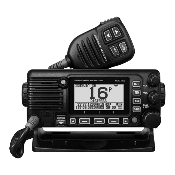
- Page 1 Owner’s Manual MATRIX NMEA2000 GPS GX2400GPS GX2400GPS/E European Version ) International ITU-R M.493-15 Class D DSC (Digital Selective Calling) Second Station Remote Microphone* TRIAL MODE − Click here for more information...
-
Page 2: Table Of Contents
TABLE OF CONTENTS QUICK REFERENCE ........... 2 9.11 PRESET CHANNELS: INSTANT ACCESS ......36 9.11.1 Programming ............36 1 GENERAL INFORMATION ......3 9.11.2 Operation .............. 36 2 PACKING LIST ..........4 9.11.3 Deletion ..............37 3 OPTIONAL ACCESSORIES ......4 9.12 MOB OPERATION .............. - Page 3 26 FCC RADIO LICENSE INFORMATION ..139 17.4 SCAN TYPE ................. 106 27 FCC NOTICE ..........140 17.5 SCAN RESUME ..............106 STANDARD HORIZON Limited Warranty ..142 17.6 MULTI WATCH ..............106 TEMPLATE for the GX2400 series ....143 17.7 PRIORITY CHANNEL ............107...
-
Page 4: Quick Reference
QUICK REFERENCE Rotate the VOL Rotate the SQL un-squelch the radio. Rotate the DIAL operating channel. 16/S 16/S 16/S channel. TRIAL MODE − Click here for more information... -
Page 5: General Information
1 GENERAL INFORMATION GX2400 channels. The GX2400 The GX2400 GX2400 The GX2400 The GX2400 receiving calls on the voice channels. The GX2400 16/S GX2400 RAM4 RAM4X RAM4 RAM4X TRIAL MODE − Click here for more information... -
Page 6: Packing List
2 PACKING LIST Transceiver T9101648 3 OPTIONAL ACCESSORIES ..............MMB-84 Remote-Access Microphone (RAM4 Microphone)* ....SSM-70H ..SSM-72H * .......... SCU-30 ... SDD-14 ......SCU-38 ........CT-100 ..............MLS-300 ........... 220SW ........240SW ..............HC2400 4 ONLINE WARRANTY REGISTRATION www.standardhorizon.com to register the GX2400 NOTE... -
Page 7: Safety Precautions (Be Sure To Read)
5 Safety Precautions (Be Sure to Read) Be sure to read these important precautions, and use this product safely. Types and meanings of the marks DANGER WARNING CAUTION Types and meanings of symbols DANGER Do not operate the device when flammable gas If thunder and lightning develop nearby when is generated. - Page 8 When smoke or strange odors are emitted Do not bend, twist, pull, heat and modify the from the radio, turn off the power and discon- power cord and connection cables in an un- nect the power cord from the socket. reasonable manner.
-
Page 9: Getting Started
6 GETTING STARTED 6.1 ABOUT VHF RADIO 6.2 SELECTING AN ANTENNA the additional gain. 6.3 COAXIAL CABLE construction. TRIAL MODE − Click here for more information... -
Page 10: Distress And Hailing (Channel 16)
tions. 6.4 DISTRESS AND HAILING (CHANNEL 16) Mayday Mayday Mayday. This is Mayday OVER NOTE The transceiver DIGITAL SELECTIVE CALLING (DSC) TRIAL MODE − Click here for more information... -
Page 11: Calling Another Vessel (Channel 16 Or 9)
6.5 CALLING ANOTHER VESSEL (CHANNEL 16 OR 9) Use of channel 16 for hailing must be limited to initial contact only. Call- channel 9 over call the other vessel. over (PTT TRIAL MODE − Click here for more information... -
Page 12: What Is The Range For Ais Receivers
6.6 WHAT IS THE RANGE FOR AIS RECEIVERS? NOTE 6.7 Accuracy of COG Speed range (knots) Accuracy of COG output to user ±3° ±1° TRIAL MODE − Click here for more information... -
Page 13: Controls And Indicators
7 CONTROLS AND INDICATORS 9 BASIC OPERATION 7.1 FRONT PANEL ⑨ ⑧ ⑦ ⑥ ⑤ ④ ③ ② ① ⑩ ⑪ ⑫ ⑬ ⑭ ⑮ ON or OFF DIAL/ENT knob to select the menu item. VOL knob (Volume control) phone volume. SQL knob (Squelch control) TRIAL MODE −... - Page 14 H/L key MENU/SET key 9.4 BASIC OPERATION OF THE SETUP MENU CLEAR key GPS Antenna BUSY Indicator LED DATA jack NOTE DISTRESS key 11.2.1 Transmitting a Distress Alert & Soft keys 16.8 SOFT KEYS 16/S key TRIAL MODE − Click here for more information...
-
Page 15: Microphone
7.2 MICROPHONE ③ ① ④ ② ⑤ ⑥ SSM-70H Microphone or SSM-72H SSM-70H Micro- phone or the SSM-72H menu items. 16/S key H/L key TRIAL MODE − Click here for more information... -
Page 16: Rear Panel
Microphone Microphone speaker microphone. 7.3 REAR PANEL ⑨ ⑥ ⑦ ⑧ ① ② ③ ④ ⑤ VHF ANT Jack GPS ANT Connector Connects the optional SCU-38 NMEA 2K Connector GND Terminal TRIAL MODE − Click here for more information... - Page 17 RAM Remote Access Microphone Connector Connects the GX2400 to the SSM-70H (RAM4) Remote Station Microphone or the SCU-30 SSM-72H (RAM4X 21 SSM-70H (RAM4) REMOTE MIC OPERATION EXTERNAL Speaker Connection Cable See section 3 OPTIONAL ACCESSORIES PA/HAIL Speaker Connection Cable (Red & Shield) 3 OPTIONAL ACCESSORIES DC Input Cable...
-
Page 18: Installation
8 INSTALLATION 8.1 SAFETY / WARNING INFORMATION Antenna Installation: 8.2 LOCATION Transceiver Unit NOTE 8.3 MOUNTING THE RADIO 8.3.1 Supplied Mounting Bracket TRIAL MODE − Click here for more information... -
Page 19: Optional Mmb-84 Flush Mount Bracket
Desktop Mounting Overhead Mounting 8.3.2 Optional MMB-84 Flush Mount Bracket GX2400. In SCU-38 to accommodate the transceiver (at least TRIAL MODE − Click here for more information... -
Page 20: Electrical Connections
8.4 ELECTRICAL CONNECTIONS CAUTION Reverse polarity battery connections will damage the radio! GPS Navigation Receiver Optional MLS-300 Optional SSM-70H External Speaker Optional MLS-300 (RAM4) Remote MIC External Speaker Optional SCU-38 External GPS Antenna Antenna Water proof Deck Outlet Fuse Black E n s u r e t h a t t h e S C U - 3 8 , t h e MLS-300 and the SSM-70H are located at a distance that does not... -
Page 21: Connection Of External Devices To The Radio
8.5 CONNECTION OF EXTERNAL DEVICES TO THE RADIO 8.5.1 Connecting the NMEA 0183/NMEA 0183-HS to the Radio External GPS Device Connections (NMEA 0183 4800 baud or NMEA 0183-HS 38400 baud) The GX2400 19.9 NMEA 0183 IN/OUT NMEA Input (GPS Information) •... -
Page 22: Internal Gps (Dsc Output) To Chart Plotter
8.5.3 Internal GPS (DSC Output) to Chart Plotter Radio Wires Plotter Connection GPS Chart Plotter Yellow: NMEA IN (+) No Connection Green: NMEA IN ( ) No Connection White: NMEA OUT (+) NMEA IN (+) Brown: NMEA OUT ( ) NMEA IN ( ) NMEA-HS OUT (+) NMEA-HS IN (+) -
Page 23: Connection To External Pa/Hail Speaker
8.5.5 Connection to External PA/HAIL Speaker White External Speaker Shield PA Speaker (horn) Shield Wire Color/Description Connection Examples 8.5.6 Connecting optional SCU-38 External GPS Antenna Connect the SCU-38 at the right). NOTE SCU-38 8.5.7 Connecting optional SCU-31 External GPS Antenna External GPS Antenna SCU-31 Radio Wires... -
Page 24: Optional Ssm-70H (Ram4) Microphone
8.5.8 Optional SSM-70H (RAM4) Microphone NOTE SSM-70H (RAM4) Remote Station Micro- SSM-70H microphone and the transceiver. WARNING Do not connect or remove the SSM-70H (RAM4) microphone while the radio is powered ON. This may result in equipment failure. SSM-70H) to the RAM SSM-70H Remote Station CT-100 External Speaker... - Page 25 Ferrite Core the nut. WARNING Connecting an External Speaker to the RAM4 Mic Cable MLS-300 RAM4 RAM4 can drive RAM4 RAM4 RAM4 MENU/ DIAL/ENT CONFIGURA- TION SELECT 3. Rotate the DIAL/ENT SPEAKER SELECT SELECT]. 4. Rotate the DIAL/ENT INTERNAL EXTERNAL SELECT CLEAR TRIAL MODE −...
-
Page 26: Optional Scu-30 Wireless Access Point Installation
8.5.9 Optional SCU-30 Wireless Access Point Installation NOTE The GX2400 SSM-72H (RAM4X addition the GX2400 the RAM4X and the GX2400. The optional SCU-30 RAM4X GX2400. WARNING Do not connect or remove the SCU-30 Wireless Access Point while the radio is powered ON. This could result in damage to the equipment. 1. - Page 27 WARNING The MMSI can be input only once, be careful not to input the incorrect MMSI number. 16.9.1 Reset the USER MMSI and ATIS CODE Programming the MMSI MENU/SET MENU DIAL/ENT MMSI/POS INFO SELECT BACK MMSI INPUT ********* SELECT SELECT FINISH FINISH *********...
-
Page 28: Confirming Gps Signal (Gps Status Display)
8.7 CONFIRMING GPS SIGNAL (GPS STATUS DISPLAY) GX2400 (GPS Status Display mode) NOTE MENU/SET MENU DIAL/ENT SELECT 3. Rotate the DIAL/ENT GPS STATUS ENTER CLEAR NOTE TRIAL MODE − Click here for more information... -
Page 29: Gps Configuration
8.8 GPS CONFIGURATION 8.8.1 Setting the GPS Time MENU/SET DIAL/ENT GPS SETUP SELECT 3. Rotate the DIAL/ENT TIME OFFSET SELECT 4. Rotate the DIAL/ENT 00:00 ENTER CLEAR 8.8.2 Setting the Time Area MENU/SET DIAL/ENT GPS SETUP SELECT 3. Rotate the DIAL/ENT TIME AREA SELECT 4. -
Page 30: Setting The Time Format
8.8.3 Setting the Time Format MENU/SET DIAL/ENT GPS SETUP SELECT 3. Rotate the DIAL/ENT TIME FORMAT SELECT 4. Rotate the DIAL/ENT 24hour 12hour ENTER setting. CLEAR 8.8.4 Setting COG to True or Magnetic MENU/SET DIAL/ENT GPS SETUP SELECT 3. Rotate the DIAL/ENT MAGNETIC VARIATION SELECT... -
Page 31: Basic Operation
9 BASIC OPERATION 9.1 TURNING THE TRANSCEIVER ON AND OFF 9.2 RECEPTION 1. Rotate the SQL 3. Rotate the SQL 4. Rotate the DIAL/ENT to select the desired desired listening level. The BUSY BUSY 9.3 TRANSMISSION THIS IS AN FCC REQUIREMENT! phone PTT NOTE normal voice. -
Page 32: Transmit Power
9.3.1 Transmit Power transceiver NOTE 9.4 BASIC OPERATION OF THE SETUP MENU transceiver MENU/SET mode screen. DIAL/ENT SELECT 3. Rotate the DIAL/ENT SELECT 4. Rotate the DIAL/ENT to select the desired setting. ENTER setting. CLEAR BACK DSC SETUP INDIVIDUAL DIRECTORY TRIAL MODE −... -
Page 33: Transmit Time-Out Timer (Tot)
9.5 TRANSMIT TIME-OUT TIMER (TOT) NOTE 9.6 SIMPLEX/DUPLEX CHANNEL USE VHF MARINE CHANNEL CHART NOTE 9.7 CHANNEL GROUP CHANNEL SETUP CHANNEL GROUP DIAL/ENT CAN * INTL insert sheet. ENTER CLEAR 24 CHANNEL ASSIGNMENTS nels in each mode. TRIAL MODE − Click here for more information... -
Page 34: Noaa Weather Channels (In Usa And Canada Only)
9.8 NOAA WEATHER CHANNELS (in USA and Canada only) the screen. NOTE 16.8 SOFT KEYS 3. Rotate the DIAL/ENT 9.8.1 NOAA Weather Alert (USA version only) The GX2400GPS 17.2 WEATHER ALERT (USA version only) NO] to return to the marine channel. NOTE TRIAL MODE −... -
Page 35: Noaa Weather Alert Testing
9.8.2 NOAA Weather Alert Testing 9.8.1 NOAA Weather Alert (USA version only) 9.9 MULTI WATCH (TO PRIORITY CHANNEL) 9.9.1 Setup the Multi Watch Operation CHANNEL SETUP MULTI WATCH DIAL/ENT DUAL TRIPLE ENTER CLEAR 9.9.2 Starting Dual Watch DIAL/ENT DUAL WATCH DUAL WATCH transceiver DUAL WATCH... -
Page 36: Scanning
NOTE 17.7 PRIORITY CHAN- 17.8 SUB CHANNEL 9.10 SCANNING The transceiver 9.10.1 Selecting Scan Type CHANNEL SETUP “SCAN TYPE” DIAL/ENT PRIORITY MEMORY ENTER setting. CLEAR CH1001 CH1001 CH88 CH09 CH88 CH09 CH1078 CH12 CH1078 CH12 Priority Channel CH68 CH15 CH68 CH15 CH1061 CH1018... -
Page 37: Memory Scanning (M-Scan)
CLEAR to radio operation. NOTE SCAN MEMORY 9.10.3 Memory Scanning (M-SCAN) MEMORY 9.10.1 Selecting Scan Type SCAN MEM SCAN received. SCAN 16/S CLEAR 9.10.4 Priority Scanning (P-SCAN) PRIORITY 9.10.1 Selecting Scan Type SCAN PRI SCAN SCAN 16/S CLEAR TRIAL MODE − Click here for more information... -
Page 38: Preset Channels: Instant Access
NOTE 17.7 PRIORITY CHANNEL 9.11 PRESET CHANNELS: INSTANT ACCESS PRESET PRESET] sound. 16.8 SOFT KEYS 9.11.1 Programming 1. Rotate the DIAL/ENT PRESET PRESET P-SET P-SET appear. 5. Repeat steps 1 through 3 to program the desired 9.11.2 Operation PRESET P-SET 3. -
Page 39: Deletion
9.11.3 Deletion P-SET 3. Rotate the DIAL/ENT PRESET P-SET DELETE 6. Repeat steps 3 through 5 to delete the undesired QUIT 9.12 MOB OPERATION The GX2400 TO WPT 12 NAVIGATION POS/TM Editing a Waypoint DISTRESS 11.2.1 Transmitting a Distress Alert TRIAL MODE −... -
Page 40: Pa/Fog Operation
9.13 PA/FOG OPERATION The GX2400 220SW 240SW GX2400 to the main radio). NOTE GX2400 Then the GX2400 PA HAIL mode: PA HAIL 220SW or 240SW FOG HORN mode: GX2400 HORN mode: GX2400 listens 9.13.1 Operating the PA HAIL mode PA VOL DIAL/ ENTER CLEAR... -
Page 41: Operating The Fog Horn Mode
9.13.2 Operating the FOG HORN mode Underway Stop Sail Towing Aground Anchor Horn Siren FOG HORN 3. Rotate the DIAL/ENT SELECT] FOG VOL DIAL/ ENTER HORN SIREN HORN HORN VOL DIAL/ ENTER CLEAR 9.13.3 Fog Signal Timing Chart TYPE PATTERN USAGE Listen Back 120s... -
Page 42: Intercom Operation
TYPE PATTERN USAGE Vessel is aground. 250ms Listen Back Vessel is at anchor. 250ms 5.25s Listen Back 9.14 INTERCOM OPERATION The optional SSM-70H (RAM4) or SSM-72H (RAM4X) remote station micro- GX2400 and the SSM-70H (RAM4) or SSM-72H (RAM4X). NOTE SSM-70H (RAM4) or SSM-72H (RAM4X) Remote Station Microphone to the transceiver. -
Page 43: Calling
NOTE PTT and RAM4 PTT CLEAR 9.14.2 Calling BELL RAM4 9.15 INTERCOM OPERATION The optional SSM-70H (RAM4) or SSM-72H (RAM4X) remote station micro- GX2400 and the SSM-70H (RAM4) or SSM-72H (RAM4X). NOTE SSM-70H (RAM4) or SSM- 72H (RAM4X) Remote Station Microphone to the GX2400. 9.15.1 Communication DIAL/ENT SELECT... -
Page 44: Calling
CLEAR 9.15.2 Calling BELL RAM4 9.16 VOICE SCRAMBLER NOTE 3. Transmit the voice message. The transmission sent 9.17 DEMO MODE NOTE ABOUT... DEMO OPERATION DIAL/ENT DEMO POSITION INPUT SELECT TRIAL MODE − Click here for more information... - Page 45 SELECT character. SELECT FINISH 6. Rotate the DIAL/ENT DEMO START SELECT DIAL/ENT START ENTER NOTE STOP TRIAL MODE − Click here for more information...
-
Page 46: Gps Operation
10 GPS OPERATION The GX2400 19.1 ORDER OF PRIORITY 10.1 DISPLAYING POSITION INFORMATION 10.1.1 GPS Information Numerical Display GPS INFO CLEAR 10.1.2 GPS Information Compass Display COMPASS CLEAR NOTE COMP 10.2 CHECKING GPS STATUS GPS STATUS CLEAR TRIAL MODE − Click here for more information... -
Page 47: Gps Logger Operation
10.3 GPS LOGGER OPERATION The GX2400 LOGGER 19.10.4 Logger Interval ). NOTE GX2400 22 CONNECTING A USB DATA TERMINAL TO THE PC Logger operation alert • • • 19.10.5 Log Erase ). TRIAL MODE − Click here for more information... -
Page 48: Digital Selective Calling (Dsc)
11 DIGITAL SELECTIVE CALLING (DSC) 11.1 GENERAL WARNING This GX2400 nautical miles. 11.2 DISTRESS ALERT The GX2400 11.2.1 Transmitting a Distress Alert NOTE 8.6.1 Maritime Mobile Service Identity (MMSI) GX2400 must receive 8.5.2 Accessory Cables TRIAL MODE − Click here for more information... - Page 49 Basic Operation DISTRESS DISTRESS received. ment is received. distress alarm sounds and Channel 16 is automati- over 16/S QUIT Transmitting a Distress Alert with Nature of Distress The transceiver DSC CALL DIST ALERT MSG NATURE NATURE OF 3. Rotate the DIAL/ENT SELECT DISTRESS TRIAL MODE −...
- Page 50 Transmitting a Distress Alert by Manually Inputting Location and Time In case the transceiver DSC CALL DIST ALERT MSG POS/TM SELECT 4. Repeat step 3 to set the position and time. SELECT FINISH DISTRESS Pausing a Distress Alert again. The transceiver TX IN: 02:10 distress alert.
-
Page 51: Receiving A Distress Alert
Canceling a Distress Alert transceiver CANCEL YES] FINISH QUIT 11.2.2 Receiving a Distress Alert sounds. 3. Rotate the DIAL/ENT the vessel in distress. ACCEPT NOTE AUTO CHANNEL CHANGE PAUSE QUIT TO WPT NOTE TRIAL MODE − Click here for more information... -
Page 52: All Ships Call
5. Rotate the DIAL/ENT SELECT STOP NOTE • assistance in the rescue attempt. • 11.10.2 Reviewing a Logged DSC RX Distress Alert and acknowledgement 11.3 ALL SHIPS CALL SAFETY URGENCY aid or an important meteorological message. This call is the a distress situation. -
Page 53: Receiving An All Ships Call
DIAL/ENT SELECT MANUAL QUIT menu. 11.3.2 Receiving an All Ships Call 3. Monitor the requested channel until the all ships voice communication is completed. ACCEPT NOTE change to the requested channel. PAUSE requested channel. NOTE QUIT TRIAL MODE − Click here for more information... -
Page 54: Individual Call
QUIT NOTE 11.10.2 Reviewing a Logged DSC RX Distress Alert and acknowledge- ment 11.4 INDIVIDUAL CALL GX2400 11.4.1 Setting up the Individual / Position Call Directory DSC SETUP INDIVIDUAL DIRECTORY DIAL/ENT SELECT 3. Rotate the DIAL/ENT NAME: SELECT SELECT TRIAL MODE − Click here for more information... -
Page 55: Setting Up The Individual Call Reply
space in the name. SELECT FINISH DIAL/ENT MMSI: SELECT SELECT SELECT FINISH DIAL/ENT SAVE ENTER through 11. CLEAR 11.4.2 Setting up the Individual Call Reply caller ID on a cellular phone. DSC SETUP INDIVIDUAL REPLY DIAL/ENT AUTO MANUAL ENTER setting. CLEAR TRIAL MODE −... -
Page 56: Enabling The Individual Call Acknowledgment
11.4.3 Enabling the Individual Call Acknowledgment ABLE UNABLE DSC SETUP INDIVIDUAL ACK. DIAL/ENT ABLE UNABLE ENTER setting. CLEAR 11.4.4 Transmitting an Individual Call channel. Individual Call using the Individual/Position Directory DSC CALL INDIVIDUAL CALL DIAL/ENT HISTORY MEMORY SELECT 3. Rotate the DIAL/ENT SELECT DIAL/ENT SELECT... - Page 57 QUIT Individual Call by Manually Entering an MMSI DSC CALL INDIVIDUAL CALL DIAL/ENT NEW ID SELECT SELECT SELECT FINISH DIAL/ENT SELECT] . To select MANUAL DSC call. ringing tone sounds. QUIT TRIAL MODE − Click here for more information...
-
Page 58: Receiving An Individual Call
11.4.5 Receiving an Individual Call 11.4.2 Setting up the Individual Call Reply Manual reply (Default setting): sounds. the individual call. ACCEPT PAUSE NOTE received. QUIT NOTE change to radio operation. ABLE UNABLE CHG CH QUIT TRIAL MODE − Click here for more information... -
Page 59: Setting Up The Individual Call Ringer
Automatic reply: sounds. 3. Monitor the requested channel until the message is completed. QUIT NOTE 11.10.2 Reviewing a Logged DSC RX Distress Alert and acknowledgement 11.4.6 Setting up the Individual Call Ringer DSC SETUP INDIVIDUAL RING DIAL/ENT ringing time. ENTER CLEAR The GX2400 DSC SETUP... -
Page 60: Group Call
3. Rotate the DIAL/ENT ENTER CLEAR DIAL/ENT 11.5 GROUP CALL 11.5.1 Setting up a Group Call Ship MMSI Ship MMSI Example Group MMSI The ITU (International Telecommunication Union) recommends program- tant step as all radios in the group must contain the same group MMSI in TRIAL MODE −... - Page 61 DSC SETUP GROUP DIRECTORY DIAL/ENT SELECT 3. Rotate the DIAL/ENT GP NAME: SELECT SELECT space in the name. SELECT FINISH DIAL/ENT GP MMSI: SELECT SELECT SELECT FINISH SAVE SELECT CLEAR TRIAL MODE − Click here for more information...
-
Page 62: Transmitting A Group Call
11.5.2 Transmitting a Group Call Group Call using the Group Directory DSC CALL GROUP CALL DIAL/ENT HISTORY MEMORY SELECT 3. Rotate the DIAL/ENT SELECT DIAL/ENT SELECT MANUAL signal. press the microphone PTT Group Call by Manually Entering an MMSI DSC CALL GROUP CALL DIAL/ENT NEW ID... -
Page 63: Receiving A Group Call
3. Rotate the DIAL/ENT SELECT SELECT FINISH DIAL/ENT SELECT MANUAL signal. press the microphone PTT 11.5.3 Receiving a Group Call produce a ringing alarm sound. ACCEPT PAUSE QUIT TRIAL MODE − Click here for more information... -
Page 64: Setting Up The Group Call Ringer
press the microphone PTT QUIT NOTE NOTE 11.10.3 Reviewing Other Logged Calls 11.5.4 Setting up the Group Call Ringer DSC SETUP DSC BEEP DIAL/ENT GROUP CALL SELECT 3. Rotate the DIAL/ENT ENTER CLEAR DIAL/ENT 11.6 POSITION REQUEST GX2400. chart plotter is connected to the GX2400 TRIAL MODE −... -
Page 65: Setting Up A Position Request Reply
NOTE 11.4 INDIVIDUAL CALL 11.6.1 Setting up a Position Request Reply DSC SETUP POSITION REPLY DIAL/ENT AUTO MANUAL the transceiver ENTER CLEAR 11.6.2 Transmitting a Position Request to Another Vessel Position Request using the Individual/Position Directory 11.4 INDIVIDUAL CALL DSC CALL POS REQUEST DIAL/ENT HISTORY... - Page 66 SELECT YES] QUIT NOTE --.--.---- _ ---.--.---- _ Position Request by Manually Entering an MMSI ing the MMSI. DSC CALL POS REQUEST DIAL/ENT NEW ID SELECT SELECT SELECT FINISH request DSC call. TRIAL MODE − Click here for more information...
-
Page 67: Receiving A Position Request
QUIT NOTE 11.6.3 Receiving a Position Request REPLY QUIT QUIT NOTE 11.10.3 Reviewing Other Logged Calls 11.6.4 Manual Input of Position Information MMSI/POS INFO POS/TM TRIAL MODE − Click here for more information... -
Page 68: Setting Up A Position Request Ringer
SELECT 4. Repeat step 3 to set the position and time. SELECT FINISH CLEAR 11.6.5 Setting up a Position Request Ringer DSC SETUP DSC BEEP DIAL/ENT POS REQUEST SELECT 3. Rotate the DIAL/ENT ENTER setting. CLEAR DIAL/ENT 11.7 POSITION REPORT 11.7.1 Transmitting a DSC Position Report Call DSC Position Report Call using the Individual/Position Directory 11.4 INDIVIDUAL CALL... - Page 69 DIAL/ENT HISTORY MEMORY SELECT 3. Rotate the DIAL/ENT SELECT POS/TM FINISH selected vessel. QUIT DSC Position Report Call by Manually Entering an MMSI DSC CALL POS REPORT DIAL/ENT NEW ID SELECT 3. Rotate the DIAL/ENT SELECT SELECT FINISH POS/TM FINISH TRIAL MODE −...
-
Page 70: Receiving A Dsc Position Report Call
selected vessel. QUIT 11.7.2 Receiving a DSC Position Report Call GX2400 QUIT 11.7.3 Navigating to the Reported Position TO WPT ENTER Stopping Navigation to the Reported Position STOP TRIAL MODE − Click here for more information... -
Page 71: Saving The Reported Position As A Waypoint
11.7.4 Saving the Reported Position as a Waypoint SAVE the DIAL/ENT NAME SELECT 11.4.1 Setting up the Individual / Position Call Directory ENTER Navigating to a Saved Waypoint 12.1.1 Starting and Stopping Navigation 11.7.5 Setting up a Position Report Ringer DSC SETUP DSC BEEP DIAL/ENT... -
Page 72: Auto Position Polling
11.8 AUTO POSITION POLLING to the programmed stations. 11.8.1 Setting up the Polling Operation DSC SETUP AUTO POSITION POLLING DIAL/ENT ENTER CLEAR 11.8.2 Setting up the Polling Time Interval DSC SETUP AUTO POS INTERVAL DIAL/ENT ENTER CLEAR 11.8.3 Selecting Vessels to be Automatically Polled NOTE 11.4.1 Setting up the Individual / Position Call Directory... -
Page 73: Enabling/Disabling Auto Pos Polling
DIAL/ENT ENTER DIAL/ENT SELECT step 4. CLEAR radio mode. 11.8.4 Enabling/Disabling Auto POS Polling DSC CALL AUTO POS POLLING DIAL/ENT ACTIVATION SELECT 3. Rotate the DIAL/ENT START STOP ENTER CLEAR 11.9 DSC TEST NOTE 11.9.1 Programming MMSI into Individual Directory 11.4.1 Setting up the Individual / Position Call Directory TRIAL MODE −... -
Page 74: Transmitting A Dsc Test To Another Vessel
11.9.2 Transmitting a DSC Test to Another Vessel DSC Test call using the Individual/Position Directory DSC CALL DSC TEST CALL DIAL/ENT HISTORY MEMORY SELECT 3. Rotate the DIAL/ENT SELECT to the other vessel. QUIT DSC Test Call by Manually Entering an MMSI DSC CALL DSC TEST CALL MANUAL... -
Page 75: Receiving A Dsc Test Call
NOTE RX TEST CALL called radio has received the test call. 11.9.3 Receiving a DSC Test Call GX2400 QUIT] 11.10 DSC LOG OPERATION The GX2400 GX2400 NOTE DSC LOG 11.10.1 Reviewing and Resending a Transmitted Logged Call DSC CALL DSC LOG DIAL/ENT TRANSMIT- SELECT... -
Page 76: Reviewing A Logged Dsc Rx Distress Alert
CALL BACK ted DSC call list. 11.10.2 Reviewing a Logged DSC RX Distress Alert and acknowledgement DSC CALL DSC LOG RX DISTRESS DIAL/ENT NOTE SELECT selected station. INFO BACK received DSC distress call list. 11.10.3 Reviewing Other Logged Calls DSC CALL DSC LOG RX OTHER CALL DIAL/ENT... -
Page 77: Deleting Logged Calls From The Dsc Log Directory
11.10.4 Deleting Logged Calls from the DSC Log Directory DSC CALL DSC LOG LOG DELETE DIAL/ENT SELECT Do you want to delete the LOG? CLEAR NOTE one time. DELETE 11.11 DSC LOOP BACK OPERATION The GX2400 DSC CALL DSC LOOP BACK CLEAR TRIAL MODE −... -
Page 78: Navigation
12 NAVIGATION The GX2400 the compass page. 12.1 WAYPOINT OPERATION 12.1.1 Starting and Stopping Navigation Navigation Using the Waypoint Directory NAVI WAYPOINT DIAL/ENT HISTORY MEMORY SELECT 3. Rotate the DIAL/ENT SELECT The navigation screen includes the distance and ( ) inside the compass. STOP Navigation by Manually Entering a Waypoint NAVI... -
Page 79: Setting Up Waypoint Directory
5. Rotate the DIAL/ENT SELECT 6. Repeat step 5 to set the position. SELECT step 5. FINISH DIAL/ENT SELECT The screen includes the distance and direction to ( ) inside the compass. STOP 12.1.2 Setting Up Waypoint Directory Marking a Position WAYPOINT SETUP MARK POSITION DIAL/ENT... - Page 80 Adding a Waypoint WAYPOINT SETUP WAYPOINT DIRECTORY DIAL/ENT SELECT 3. Rotate the DIAL/ENT NAME: SELECT SELECT FINISH 5. Rotate the DIAL/ENT POSITION: SELECT] FINISH 6. Rotate the DIAL/ENT SAVE SELECT CLEAR Editing a Waypoint WAYPOINT SETUP WAYPOINT DIRECTORY DIAL/ENT EDIT SELECT 3.
-
Page 81: Selecting The Display Range
Deleting a Waypoint WAYPOINT SETUP WAYPOINT DIRECTORY DIAL/ENT DELETE SELECT 3. Rotate the DIAL/ENT SELECT DIAL/ENT SELECT CLEAR Saving a DSC Position Call as a Waypoint GX2400 11.7.4 Saving the Reported Position as a Waypoint 12.1.3 Selecting the Display Range WAYPOINT SETUP DISPLAY RANGE DIAL/ENT... -
Page 82: Routing Operation
12.2 ROUTING OPERATION The GX2400 Via29 Via3 Via30 Via2 Current Via1 position Routing to a Waypoint 12.2.1 Setting Up Routing Directory NOTE Adding a Route WAYPOINT SETUP ROUTE DIRECTORY DIAL/ENT SELECT 3. Rotate the DIAL/ENT NAME: SELECT DIAL/ENT SELECT FINISH 5. - Page 83 BACK DIAL/ENT SAVE ENTER CLEAR Editing a Route WAYPOINT SETUP ROUTE DIRECTORY DIAL/ENT EDIT SELECT 3. Rotate the DIAL/ENT SELECT route is updated. 5. Rotate the DIAL/ENT SAVE SELECT CLEAR Deleting a Route WAYPOINT SETUP ROUTE DIRECTORY DIAL/ENT DELETE SELECT 3.
-
Page 84: Starting And Stopping Route Navigation
12.2.2 Starting and Stopping Route Navigation NAVI ROUTE DIAL/ENT HISTORY MEMORY SELECT 3. Rotate the DIAL/ENT SELECT ARRIVED target point is reached. YES] STOP 12.2.3 Changing the Destination NEXT TG DIAL/ENT SELECT appears. 12.2.4 Selecting Automatic or Manual Routing WAYPOINT SETUP ROUTING OPERATION DIAL/ENT AUTO... -
Page 85: Gm Operation
13 GM OPERATION GX2400 locations. 13.1 SETTING UP GM OPERATION 13.1.1 Setting Up GM Group Directory NOTE • 11.5.1 Setting up a Group Call • 11.4.1 Setting up the Individual / Position Call Directory GM SETUP GM GROUP DIRECTORY DIAL/ENT SELECT 3. -
Page 86: Setting Up The Polling Time Interval
DIAL/ENT SELECT DIAL/ENT SELECT BACK BACK NAME: GM ID: 11. Rotate the DIAL/ENT SAVE ENTER through 11. CLEAR 13.1.2 Setting Up the Polling Time Interval GM SETUP INTERVAL DIAL/ENT ENTER CLEAR 13.1.3 Enabling/Disabling Transmission during GM Operation GM SETUP GM TX DIAL/ENT ENTER CLEAR... -
Page 87: Starting Gm Operation
13.2 STARTING GM OPERATION NOTE 13.1.1 Setting Up GM Group Directory DIAL/ENT SELECT appears. CLEAR 13.2.1 Changing the GM Group Being Monitored TG LIST CHG GRP 3. Rotate the DIAL/ENT SELECT] CLEAR TRIAL MODE − Click here for more information... -
Page 88: Transmitting A Dsc Call To A Group Member
13.2.2 Transmitting a DSC Call to a Group Member TG LIST DIAL/ENT SELECT CALL 13.2.3 Starting Navigation to a Group Member TG LIST 3. Rotate the DIAL/ENT SELECT TO WPT BACK TRIAL MODE − Click here for more information... -
Page 89: Automatic Identification System (Ais)
14 AUTOMATIC IDENTIFICATION SYSTEM (AIS) 14.1 GENERAL NOTE The GX2400 transmissions. The GX2400 Classes of AIS: (and others in some countries). The GX2400 the internal Dual Channel AIS receiver. 14.2 AIS OPERATION The GX2400 NOTE AIS targets. TRIAL MODE − Click here for more information... -
Page 90: Displaying The Ais Target Information Screen
Vessel Location Range Ring AIS Target Selected AIS Target DIAL/ENT Rotating the DIAL/ENT DIAL/ENT Information of the AIS Target icon. NOTE CLEAR 14.2.1 Displaying the AIS Target Information Screen RANGE TG LIST received. FUNC TG LIST 3. Rotate the DIAL/ENT SELECT DANGER DIAL/... -
Page 91: Changing The Ais Range
14.2.2 Changing the AIS Range RANGE the center and right side to select the radius range to BACK NOTE 19.7 UNITS OF MEASURE 14.2.3 Transmitting an Individual Call to an AIS Ship GX2400 to transmit a DSC individual call to a received AIS TG LIST 3. -
Page 92: Cpa/Tcpa Alarm Functions
GX2400 vessel. QUIT CLEAR 14.2.4 CPA/TCPA Alarm Functions 14.3.1 14.3.2 TCPA NOTE to the AIS mode. INFO CALL calls. EXIT 14.2.3 Transmitting an Individual Call to an AIS Ship TRIAL MODE − Click here for more information... -
Page 93: Changing The Compass Display
14.2.5 Changing the Compass Display 19.2 COMPASS DIRECTION 14.3 AIS SETUP 14.3.1 CPA alarm distance. AIS SETUP DIAL/ENT 0.1nm 20nm ENTER setting. CLEAR 14.3.2 TCPA alarm. AIS SETUP TCPA DIAL/ENT 1min 60min ENTER setting. CLEAR TRIAL MODE − Click here for more information... -
Page 94: Cpa/Tcpa Alarm
14.3.3 CPA/TCPA Alarm AIS SETUP CPA/TCPA ALARM DIAL/ENT TCPA SELECT 3. Rotate the DIAL/ENT ENTER setting. CLEAR NOTE and optional RAM4 and RAM4X 14.3.4 IGNORE VESSELS AIS SETUP CPA/TCPA ALARM DIAL/ENT IGNORE VESSELS SELECT 3. Rotate the DIAL/ENT SELECT 4. Rotate the DIAL/ENT NAME: SELECT TRIAL MODE −... - Page 95 in the ignore vessel. SELECT SELECT FINISH 9. Rotate the DIAL/ENT MMSI: SELECT SELECT entered. SELECT FINISH DIAL/ENT SAVE SELECT CLEAR TRIAL MODE − Click here for more information...
-
Page 96: Nmea 2000 Setup
15 NMEA 2000 SETUP 15.1 SELECT DEVICE NMEA2000 SETUP SELECT DEVICE DIAL/ENT SELECT CLEAR NOTE SEARCH 15.2 DEVICE NUMBER GX2400 15.1 SELECT DEVICE NMEA2000 SETUP DEVICE NUMBER DIAL/ENT SELECT SELECT FINISH CLEAR TRIAL MODE − Click here for more information... -
Page 97: System Number
15.3 SYSTEM NUMBER 15.1 SELECT DEVICE NMEA2000 SETUP SYSTEM NUMBER SELECT SELECT FINISH CLEAR 15.4 SUMMARY OF THE NMEA 2000 SETUP Item Description Default Value Page 15.5 COMPATIBLE NMEA 2000 PGN LIST Receive Transmit Magnetic Variation Speed TRIAL MODE − Click here for more information... - Page 98 Receive Transmit Report Report Station) Related Data Message Message TRIAL MODE − Click here for more information...
-
Page 99: Configuration Setup
16 CONFIGURATION SETUP 16.1 DISPLAY MODE the radio. CONFIGURATION DISPLAY MODE DIAL/ENT DAY MODE NIGHT MODE setting. use. ENTER CLEAR 16.2 DIMMER ADJUSTMENT CONFIGURATION DIMMER DIAL/ENT ENTER CLEAR 16.3 DISPLAY CONTRAST CONFIGURATION CONTRAST DIAL/ENT ENTER CLEAR TRIAL MODE − Click here for more information... -
Page 100: Key Beep
16.4 KEY BEEP CONFIGURATION KEY BEEP DIAL/ENT ENTER CLEAR 16.5 FOG ALERT TONE FREQUENCY CONFIGURATION FOG FREQUENCY DIAL/ENT 200Hz 850Hz ENTER setting. CLEAR NOTE TRIAL MODE − Click here for more information... -
Page 101: Listen Back
16.6 LISTEN BACK CONFIGURATION LISTEN BACK DIAL/ENT ENTER setting. CLEAR 16.7 STATION NAME microphone. CONFIGURATION STATION NAME the DIAL/ENT SELECT 3. Rotate the DIAL/ENT SELECT 5. Repeat steps 3 and 4 until the name is complete. The DIAL/ENT SELECT FINISH DIAL/ENT SSM-70H SELECT... -
Page 102: Soft Keys
SELECT space in the name. DIAL/ENT SELECT FINISH CLEAR 16.8 SOFT KEYS 16.8.1 Key Assignment CONFIGURATION SOFT KEY DIAL/ENT KEY ASSIGN- MENT SELECT 3. Rotate the DIAL/ENT SELECT 4. Rotate the DIAL/ENT ENTER CLEAR TRIAL MODE − Click here for more information... - Page 103 SOFT KEY DISPLAY FUNCTION ICON scan Starts and stops logging position data nighttime mode TRIAL MODE − Click here for more information...
-
Page 104: Key Timer
16.8.2 Key Timer CONFIGURATION SOFT KEY DIAL/ENT KEY TIMER SELECT 3. Rotate the DIAL/ENT ENTER CLEAR 16.9 RESET CONFIGURATION RESET DIAL/ENT DSC/GM SETUP WAYPOINT SETUP CHANNEL SETUP GPS SETUP CONFIGURA- TION FACTORY USER MMSI ATIS CODE . USER MMSI ATIS CODE 16.9.1 Reset the USER MMSI and ATIS CODE SELECT... -
Page 105: Reset The User Mmsi And Atis Code
16.9.1 Reset the USER MMSI and ATIS CODE To request the Reset Code The Information Necessary to obtain the Reset Code: • Model name 8.6.1 Maritime Mobile Service Identity (MMSI) 20 ATIS SETUP Checking the Request code Contact Information USA/Canada Europe Checking the Request code CONFIGURATION... - Page 106 Resetting the USER MMSI and ATIS codes Check- ing the Request code DIAL/ENT PASSWORD SELECT SELECT SELECT FINISH Completed! on the screen. code again. NOTE TRIAL MODE − Click here for more information...
-
Page 107: Summary Of The Configuration Setup
16.10 SUMMARY OF THE CONFIGURATION SETUP Item Description Default Value Page horn TRIAL MODE − Click here for more information... -
Page 108: Channel Function Setup
17 CHANNEL FUNCTION SETUP 17.1 CHANNEL GROUP 9.7 CHANNEL GROUP 17.2 WEATHER ALERT (USA version only) CHANNEL SETUP WX ALERT DIAL/ENT ENTER CLEAR 17.3 SCAN MEMORY 9.10.2 Programming Scan Memory 17.4 SCAN TYPE MEMORY PRIORITY 9.10.1 Selecting Scan Type 17.5 SCAN RESUME CHANNEL SETUP SCAN RESUME DIAL/ENT... -
Page 109: Priority Channel
17.7 PRIORITY CHANNEL CHANNEL SETUP PRIORITY CHANNEL DIAL/ENT ENTER CLEAR 17.8 SUB CHANNEL CHANNEL SETUP SUB CHANNEL DIAL/ENT ENTER CLEAR 17.9 CHANNEL NAME Example CHANNEL SETUP CHANNEL NAME DIAL/ENT SELECT SELECT TRIAL MODE − Click here for more information... -
Page 110: Rx Led Dimmer Adjustment
SELECT FINISH CLEAR NOTE NAME 17.10 RX LED DIMMER ADJUSTMENT CHANNEL SETUP RX LED DIMMER DIAL/ENT ENTER CLEAR 17.11 NOISE CANCELLATION CHANNEL SETUP NOISE CANCEL DIAL/ENT TX MODE SELECT 3. Rotate the DIAL/ENT ENTER TRIAL MODE − Click here for more information... -
Page 111: Audio Filter Operation
4. Rotate the DIAL/ENT RX MODE SELECT 5. Rotate the DIAL/ENT LEVEL1 LEVEL4 ENTER CLEAR 17.12 AUDIO FILTER OPERATION CHANNEL SETUP AF PITCH CONTROL DIAL/ENT operation. ENTER CLEAR 17.13 SCRAMBLER SETUP CVS2500A (FVP-42 NOTE • • CHANNEL SETUP SCRAMBLER DIAL/ENT TYPE SELECT 3. -
Page 112: Summary Of The Cannel Function Setup
4. Rotate the DIAL/ENT CODE SELECT 5. Rotate the DIAL/ENT SELECT NOTE 6. Rotate the DIAL/ENT ENTER CLEAR 17.14 SUMMARY OF THE CANNEL FUNCTION SETUP Item Description Default Value Page Selects the channel group (Depending on the transceiver version) scan 3 sec cation settings TRIAL MODE −... -
Page 113: Dsc Setup
18 DSC SETUP 18.1 INDIVIDUAL DIRECTORY The GX2400 11.4.1 Setting up the Individual / Position Call Directory 18.2 INDIVIDUAL REPLY to caller ID on a cellular phone. 11.4.2 Setting up the Individual Call Reply 18.3 INDIVIDUAL ACKNOWLEDGMENT 11.4.3 Enabling the Individual Call Acknowledgment details. -
Page 114: Position Reply
18.6 POSITION REPLY The GX2400 11.6.1 Setting up a Position Request Reply 18.7 AUTO POSITION POLLING The GX2400 11.8 AUTO POSITION POLLING 18.8 AUTO POSITION INTERVAL 11.8.2 Setting up the Polling Time Interval 18.9 AUTO CHANNEL CHANGE the GX2400 DSC SETUP AUTO CHANNEL CHANGE DIAL/ENT ENTER... -
Page 115: Action Timer
18.10 NO ACTION TIMER DSC SETUP NO ACTION TIMER DIAL/ENT ENTER CLEAR 18.11 WAIT TIME FOR POSITION FIX DSC SETUP POS UNFIX WAITING TIME DIAL/ENT ENTER CLEAR 18.12 DSC BEEP 11.5.4 Setting up the Group Call Ringer TRIAL MODE − Click here for more information... -
Page 116: Summary Of The Dsc Setup Menu
18.13 SUMMARY OF THE DSC SETUP MENU Item Description Default Value Page individual call call an individual call or a position request is received group calling ing a position call TRIAL MODE − Click here for more information... -
Page 117: Gps Setup
19 GPS SETUP 19.1 ORDER OF PRIORITY GPS SETUP ORDER OF PRIORITY DIAL/ENT NMEA2000 NMEA-0183 ENTER CLEAR NOTE 19.2 COMPASS DIRECTION GPS SETUP COMPASS DIRECTION DIAL/ENT COURSE-UP NORTH-UP ENTER CLEAR 19.3 LOCATION FORMAT GPS SETUP LOCATION FORMAT DIAL/ENT ddd°mm.mmmm ddd°mm’ss” ENTER CLEAR TRIAL MODE −... -
Page 118: Time Offset
19.4 TIME OFFSET 8.8.1 Setting the GPS Time 19.5 TIME AREA 8.8.2 Setting the Time Area 19.6 TIME FORMAT 8.8.3 Setting the Time Format 19.7 UNITS OF MEASURE GPS SETUP UNIT OF MEASURE DIAL/ENT set. SELECT 4. Rotate the DIAL/ENT ENTER CLEAR 19.8 MAGNETIC VARIATION... -
Page 119: Nmea 0183 In/Out
19.9 NMEA 0183 IN/OUT 19.9.1 Data Speed GPS SETUP NMEA 0183 IN/OUT DIAL/ENT DATA SPEED SELECT 3. Rotate the DIAL/ENT 4800bps 38400bps ENTER CLEAR 19.9.2 Output Sentences GPS SETUP NMEA 0183 IN/OUT DIAL/ENT OUTPUT SENTENCES SELECT 3. Rotate the DIAL/ENT SELECT 4. -
Page 120: Internal Gps Unit
NOTE • 19.1 ORDER OF PRIORITY • • • 19.10 INTERNAL GPS UNIT SCU-38 19.10.1 Position Data Output GPS SETUP INTERNAL GPS UNIT DIAL/ENT POS DATA OUTPUT SELECT 3. Rotate the DIAL/ENT NMEA 2000 NMEA 0183 SELECT 4. Rotate the DIAL/ENT ENTER CLEAR TRIAL MODE −... -
Page 121: Pinning
19.10.2 Pinning GPS SETUP INTERNAL GPS UNIT DIAL/ENT PINNING SELECT 3. Rotate the DIAL/ENT not update its position unless the ENTER CLEAR operation. 19.10.3 GPS SETUP INTERNAL GPS UNIT DIAL/ENT D-GPS SELECT 3. Rotate the DIAL/ENT ENTER CLEAR TRIAL MODE − Click here for more information... -
Page 122: Logger Interval
19.10.4 Logger Interval GPS SETUP INTERNAL GPS UNIT DIAL/ENT LOGGER INTERVAL SELECT 3. Rotate the DIAL/ENT ENTER NOTE: CLEAR 19.10.5 Log Erase GPS SETUP INTERNAL GPS UNIT DIAL/ENT LOG ERASE SELECT CLEAR TRIAL MODE − Click here for more information... -
Page 123: Summary Of The Gps Setup
19.11 SUMMARY OF THE GPS SETUP Item Description Default Value Page Selects the compass direction to ddd°mm.mmmm altitude nm (nautical mile) Selects the connection device TRIAL MODE − Click here for more information... -
Page 124: Atis Setup
20 ATIS SETUP The GX2400GPS/E WARNING The ATIS code can be inputted only once, please be careful not to input the incorrect ATIS code. 16.9.1 Reset the USER MMSI and ATIS CODE 20.1 ATIS CODE PROGRAMMING ATIS SETUP ATIS CODE SELECT to th SELECT]... -
Page 125: Atis Ch Group
20.2 ATIS CH GROUP The GX2400GPS/E channel group. ATIS SETUP ATIS GROUP DIAL/ENT SELECT *(Depending on the region setting.) 3. Rotate the DIAL/ENT ENTER BACK NOTE • • TRIAL MODE − Click here for more information... -
Page 126: Ssm-70H ( Ram4 ) Remote Mic Operation
21 SSM-70H ( RAM4 ) REMOTE MIC OPERATION NOTE GX2400 SSM-70H operation is the same as the GX2400 SSM-70H SSM-70H SSM-70H CT-100. The Intercom SSM-70H and the GX2400 21.1 REMOTE MIC CONTROLS Power/VOL knob TRIAL MODE − Click here for more information... - Page 127 DIAL/ENT knob DIAL/ENT to select the desired menu item. SQL key (Squelch control) switch CLEAR/ Microphone NOTE MENU key Display MMSI and ATIS Display Area (Fixed) Channel and Operation status Display area TRIAL MODE − Click here for more information...
-
Page 128: Ram4 Soft Key Assignment
Soft keys 21.2 RAM4 SOFT KEY ASSIGNMENT Strobe Light STROBE 16/S key channel. Speaker DATA jack SSM-70H (RAM4 NOTE DISTRESS key 11 DIGITAL SELECTIVE CALLING (DSC) 21.2 RAM4 SOFT KEY ASSIGNMENT RAM4 DISPLAY SOFT KEY ICON FUNCTION and marine TRIAL MODE − Click here for more information... -
Page 129: Key Assignment
DISPLAY SOFT KEY ICON FUNCTION channel scan channel settings. Starts and stops logging position data and marine and nighttime mode NOTE optional SSM-70H (RAM4) remote microphone. 21.2.1 Key Assignment SSM-70H (RAM4 NOTE DIAL/ENT the SSM-70H (RAM4). CONFIGURATION SOFT KEY (RAM4) TRIAL MODE −... -
Page 130: Connecting A Usb Data Terminal To The Pc
DIAL/ENT KEY ASSIGN- MENT SELECT 3. Rotate the DIAL/ENT SELECT 4. Rotate the DIAL/ENT ENTER] NONE assignment is removed. CLEAR/ 22 CONNECTING A USB DATA TERMINAL TO THE PC The GX2400 ® DATA GX2400. USB Cable (Supplied with GX2400GPS) CAUTION The DATA TRIAL MODE −... -
Page 131: Maintenance
• Mounting Bracket Knob • Microphone Hanger • SSM-70H (RAM4 Microphone) Routing Cable Assembly • USB Cable 23.2 FACTORY SERVICE In USA and Canada Standard Horizon Attention Marine Repair Department Telephone ( ) 366-4566 In Europe Yaesu ( UK ) Ltd... -
Page 132: Troubleshooting Chart
23.3 TROUBLESHOOTING CHART SYMPTOM PROBABLE CAUSE REMEDY to turn the radio on. T r a n s c e i v e r c o n n e c t e d t o engine runs. Sound is not emit- Receiving station Antenna. -
Page 133: Channel Assignments
24 CHANNEL ASSIGNMENTS 24.1 GX2400GPS VHF MARINE CHANNEL CHART CHANNEL USE VTS in selected areas U.S. Government Only, Coast Guard 156.150 Commercial Commercial ( ( Recreational ) Commercial Commercial. VTS in selected areas. - - - movement ( State Controlled ( Commercial Commercial (USA) U.S. - Page 134 VHF MARINE CHANNEL CHART CHANNEL USE on channel 16 (USA) on channel 16 (Canada) 1023 157.150 U.S. Government Only - - - - - - - - - Public Coast: Coast Guard; 1061 156.075 VTS in selected areas. Public Correspondence ( Marine Operator ) , 1064 156.225 Port operation, ship movement...
- Page 135 VHF MARINE CHANNEL CHART CHANNEL USE ( Recreational ) and Ship movement and Ship movement ( Recreational ) Commercial Commercial U.S. Government Only - Environmental 1081 157.075 protection operations. (USA) Canadian Coast Guard Only (Canada) U.S. Government Only (USA) 1082 157.125 Canadian Coast Guard Only (Canada) U.S.
-
Page 136: Gx2400Gps/E
24.2 GX2400GPS/E CHANNEL USE TX (MHz) RX (MHz) SIMPLEX/DUPLEX LOW PWR All countries Germany (except Germany) – – – – – – – – – – – – – – – – – – – – – – – – –... - Page 137 CHANNEL USE TX (MHz) RX (MHz) SIMPLEX/DUPLEX LOW PWR All countries Germany (except Germany) – – – – – – – – – – – – – – – – – – – – – – – – – – –...
-
Page 138: Specifications
25 SPECIFICATIONS GENERAL Channels ..........*(Depending on the region setting) ..........................11 V to 16.5 V Current Drain ..............................Transmit ....................................................................................................................................................... Dimensions ( ) ......Flush-Mount Dimensions ( ) .................. - Page 139 RECEIVER (for Voice and DSC) ..........................................................................Audio Response ............. Channel Spacing ................. DSC Format ................ITU-R M.493-15 ..............RECEIVER (for AIS) ............................................. INTERNAL GPS RECEIVER Receiver Channels ..............66 Channels ...............
-
Page 140: Dimensions
25.1 DIMENSIONS 6.3” (159mm) 6.2” (156mm) 1.7” (44mm) 4.8” (121.8mm) 7.1” (180mm) 1.2” (30.8mm) 3.8” (97.4mm) 7.1” (180mm) 1.5” (36.9mm) 7.8” (197.4mm) 6.3” (159mm) 6.2” (156mm) 7.1” (180mm) 1.7” (44mm) 4.8” (121.8mm) 1.2” (30.8mm) 3.8” (97.4mm) 7.1” (180mm) 1.5” (36.9mm) 6.8”... -
Page 141: Fcc Radio License Information
26 FCC RADIO LICENSE INFORMATION (FCC) requirements that regulate the Maritime Radio Service. 26.1 STATION LICENSE 26.2 RADIO CALL SIGN 26.3 CANADIAN SHIP STATION LICENSING 26.4 FCC / IC INFORMATION license application................................................................FCC ID ..................IC .................. -
Page 142: Fcc Notice
27 FCC NOTICE NOTICE NOTICE Reorient or relocate the receiving antenna. WARNING TRIAL MODE − Click here for more information... - Page 143 FCC APPLICATION ISED APPLICATION TRIAL MODE − Click here for more information...
-
Page 144: Standard Horizon Limited Warranty
STANDARD HORIZON Limited Warranty On-line Warranty Registration: www.standardhorizon.com Warranty Terms: Limitations of Warranty: Warranty Procedures: purchased. ( or a replacement product ) Other conditions: TRIAL MODE − Click here for more information... -
Page 145: Template For The Gx2400 Series
cut here TEMPLATE for the GX2400 series 161 mm Use this template to mark the location where the... - Page 146 TRIAL MODE − Click here for more information...
- Page 147 Declaration of Conformity EU Declaration of Conformity Disposal of Electronic and Electrical Equipment ATTENTION – Conditions of usage equipment. – – – – TRIAL MODE − Click here for more information...
- Page 148 Copyright 2020 Y Y ESU MUSEN CO., LTD. All rights reserved. No portion of this manual may be reproduced without the permission of Y Y ESU MUSEN CO., LTD. YAESU MUSEN CO., LTD. Tennozu Parkside Building 2-5-8 Higashi-Shinagawa, Shinagawa-ku, Tokyo 140-0002 Japan YAESU USA 2005M-BC Printed in China...