Table of Contents
Advertisement
Advertisement
Table of Contents

Related Manuals for Foxconn FlamingBlade GTI


Summary of Contents for Foxconn FlamingBlade GTI
- Page 1 Flaming Blade Series Motherboard User’s Manual...
- Page 2 Statement: This manual is the intellectual property of Foxconn, Inc. Although the information in this manual may be changed or modified at any time, Foxconn does not obligate itself to inform the user of these changes. Trademark: All trademarks are the property of their respective owners.
-
Page 3: Declaration Of Conformity
Declaration of conformity HON HAI PRECISION INDUSTRY COMPANY LTD 66 , CHUNG SHAN RD., TU-CHENG INDUSTRIAL DISTRICT, TAIPEI HSIEN, TAIWAN, R.O.C. declares that the product Motherboard Flaming Blade/Flaming Blade GTI is in conformity with (reference to the specification under which conformity is declared in accordance with 89/336 EEC-EMC Directive) ■... - Page 4 Declaration of conformity Trade Name: FOXCONN Model Name: Flaming Blade/Flaming Blade GTI Responsible Party: PCE Industry Inc. Address: 458 E. Lambert Rd. Fullerton, CA 92835 Telephone: 714-738-8868 Facsimile: 714-738-8838 Equipment Classification: FCC Class B Subassembly Type of Product: Motherboard Manufacturer:...
-
Page 5: Installation Precautions
Installation Precautions ■ Electrostatic discharge (ESD) is the sudden and momentary electric current that flows between two objects at different electrical potentials. Normally it comes out as a spark which will quickly damage your electronic equipment. Please wear an electrostatic discharge (ESD) wrist strap when handling components such as a motherboard, CPU or memory. -
Page 6: Table Of Contents
TABle oF CoNTeNTS Chapter 1 Product Introduction Package List ....................2 Product Specifications ...................3 Layout ......................5 Back Panel Connectors .................6 Chapter 2 Hardware Install Install the CPU and CPU Cooler ..............9 Install the Memory ..................12 Install an Expansion Card................14 Install other Internal Connectors..............15 Jumpers .......................19 Onboard Button ...................21 Onboard LED....................22... - Page 7 OC Gear ....................60 Configuration ..................61 FOX LiveUpdate Local Update ..................62 Online Update ..................64 Configure ....................67 About & Help ..................69 FOX LOGO ....................70 FOX DMI ......................71 Chapter 5 RAID Configuration RAID Configuration Introduction ..............74 Intel Matrix Storage Manager ..............76 ® Create a RAID Driver Diskette..............77 BIOS Configuration..................79 Create RAID in BIOS ...................79 Install a New Windows XP .................103...
- Page 8 Thank you for buying Flaming Blade/Flaming Blade GTI, a Foxconn Quantum Force series motherboard. Quantum Force products are Foxconn's high end enthusiast products engineered to maximize computing power, providing all you need for break-through performance. With advanced overclocking capabilities and a range of connectivity...
-
Page 9: Package List
Package list Check your product package for the following items: Motherboard Foxconn Flaming Blade/Flaming Blade GTI motherboard Cables 1 X Ultra DMA cable 3 X SATA Signal cables Accessory I/O Shield Quantum Force SLI Bridge(Only for Flaming Blade) Application CD Foxconn motherboard support CD Documentation User’s Manual... -
Page 10: Product Specifications
1-1 Product Specifications Support LGA1366 Intel ® CPU: Core i7 and Core i7 Extreme Series processors Supports Intel ® Hyper-Threading Technology Up to 6.4GT/s North Bridge: Intel ® X58 chipset Chipset South Bridge: Intel ® ICH10R(Flaming Blade) Intel ® ICH10(Flaming Blade GTI) Memory 3 x 240-pin DDR3 DIMM sockets Supports up to 12GB of system memory... - Page 11 1 x Power fan header (3-pin)(NB_FAN1) 1 x IDE connector (Controlled by JMicron JMB363, for Flaming Blade/ Controlled by JMicron JMB368, for Flaming Blade GTI) 6 x SATA connectors 2 x USB 2.0 connectors (Supporting 4 x USB devices) Back Panel 1 x PS/2 Keyboard port Connectors 1 x Optical S/PDIF out connector...
-
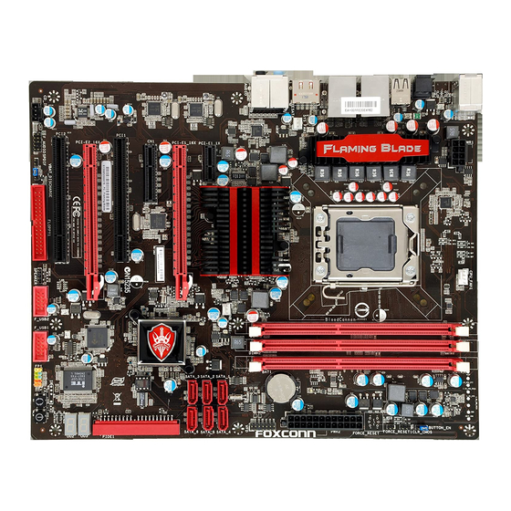
Page 12: Layout
1-2 layout 1. 8-pin ATX 12V Power Connector 17. IDE Connector 2. System Fan Header 18. SATA Connectors 3. PCI Express x1 Slot(Only for Flaming Blade) 19. South Bridge: Intel® ICH10R(Flaming 4. PCI Express x16 Slots Blade)/ Intel® ICH10(Flaming Blade GTI) 5. -
Page 13: Back Panel Connectors
1-3 Back Panel Connectors Back Panel of Flaming Blade PS/2 Keyboard Port LAN Ports Line Out Line In Clear CMOS Button Rear Speaker Subwoofer Side Speaker Microphone In USB Ports Optical USB Ports External SATA Audio Ports S/PDIF Out Ports Back Panel of Flaming Blade GTI PS/2 Keyboard Port LAN Port... - Page 14 ■ Make sure the power supply is turned off before pressing the CLR_CMOS button to clear CMOS. ■ Push down the CLR_CMOS button and hold it there for a couple of seconds to clear the CMOS completely, then release. 4. optical S/PDIF out Connector This connector provides digital audio out to an external audio system that supports digital optical audio.
- Page 15 This chapter introduces the hardware installation process, including the installation of the CPU, memory, power supply, slots, pin headers and the mounting of jumpers. Caution should be exercised during the installation of these modules. Please refer to the motherboard layout prior to any installation and read the contents in this chapter carefully.
-
Page 16: Install The Cpu And Cpu Cooler
2-1 Install the CPU and CPU Cooler Read the following guidelines before you begin to install the CPU : ■ Make sure that the motherboard supports the CPU. ■ Always turn off the computer and unplug the power cord from the power supply before installing the CPU to prevent hardware damage. - Page 17 Follow the steps to install the CPU onto the CPU socket : Before installing the CPU, make sure to turn off the computer and unplug the power cord from the power outlet to prevent damage to the CPU. 1. Release the CPU socket lever. 2.
-
Page 18: Install The Cpu Cooler
Install the CPU Cooler Follow the steps below to correctly install the CPU cooler on the motherboard. The Foxconn QuantumForce Flaming Blade series come equipped with socket 1366 and socket 775 mounting holes to support current heatsinks. Socket 775 Push-Pin Heatsinks like the Intel 775 stock Heatsinks will NOT fit properly since the 1366 CPU socket is slightly higher than the 775 CPU socket! 2. -
Page 19: Install The Memory
■ Use caution when removing the CPU cooler because the thermal grease may stick it to the CPU. If the Heatsink is stuck slightly twist it left and right until you can remove it. Be patient and do not use a lot of force. ■... -
Page 20: Installing A Memory
Installing a Memory Before installing a memory module, make sure to turn off the computer and unplug the power cord from the power outlet to prevent damage to the memory module. Be sure to install DDR3 DIMMs on this motherboard. Notch If you take a look at front side of memory module, it has asymmetric pin counts on both sides separated by a notch in the middle, so it can only fit in one direction. -
Page 21: Install An Expansion Card
2-3 Install an expansion Card ■ Make sure the motherboard supports the expansion card. Carefully read the manual that came with your expansion card. ■ Always turn off the computer and unplug the power cord from the power outlet before installing an expansion card to prevent hardware damage. -
Page 22: Install Other Internal Connectors
2-4 Install other Internal Connectors Power Connectors This motherboard uses an ATX power supply. In order not to damage any device, make sure all the devices have been installed properly before applying the power supply. 24-pin ATX power connector : PWR2 PWR2 is the ATX power supply connector. - Page 23 8-pin ATX 12 V Power Connector : PWR1 The 8-pin ATX 12V power supply connects to PWR1 and provides power to the CPU. Pin # Definition Pin # Definition +12V +12V +12V +12V +12V PWR1 Connect a 4-pin power plug We recommend you using an 8-pin ATX 12V power supply.
- Page 24 Front Panel Connector : FP1 This motherboard includes one connector for connecting the front panel switch and LED Indicators. HDD-LED PWR-LED RESET-SW PWR-SW Hard Disk leD Connector (HDD-leD) EMPTY Connect to the chassis front panel IDE indicator LED. It indicates the active status of the hard disks. This 2-pin connector is directional with +/- sign.
- Page 25 POWER SENSE CONTROL CPU_FAN1 VFD Connector : VFD The VFD Connector can be connected to the Foxconn Quantum Force OC Panel, which can be installed in RESET any standard 5.25" optical drive bay. It can be used GPIO to display the Port80 Debug codes during Bootup,...
-
Page 26: Jumpers
2-5 Jumpers For some features needed, users can change the jumper settings on this motherboard to modify them. This section explains how to use the various functions of this motherboard by changing the jumper settings. Users should read the following content carefully prior to modifying any jumper setting. Description of Jumpers 1. - Page 27 Clear CMoS Jumper: ClR_CMoS The motherboard uses CMOS RAM to store the basic hardware information (such as BIOS data, date, time information, hardware password...etc.). Clear CMOS data is the fast way to go back to factory default when the BIOS settings were mistakenly modified. The steps to clear CMOS data are : 1.
-
Page 28: Onboard Button
Force Reset Jumper: FoRCe_ReSeT1 (only for Flaming Blade) When set the jumper to1-2 closed, the system will shutdown and auto power on after 4 seconds. Enable Disable (Default) FORCE_RESET1 2-6 onboard Button(only for Flaming Blade) Power on Button: PoWeR_oN Push the power on button to power on the system. Reset Button: ReSeT Push the reset button to reboot the system. -
Page 29: Onboard Led
2-7 onboard leD DRAM Power leD: The LED lights up indicating the system is on or the system is staying at S1 or S3 sleeping state. +5V Standby leD: It will light whenever the power supply that connected to the motherboard is switched on. DIMM3 SPD Detect leD: The Normal status is on. - Page 30 This chapter explains how to change system settings through the BIOS Setup menus. Detailed descriptions of the BIOS parameters are also provided. You have to run the Setup Program when the following cases occur : 1. An error message appears on the screen during the system Power On Self Test (POST) process.
-
Page 31: Enter Bios Setup
enter BIoS Setup The BIOS is the communication bridge between hardware and software, correctly setting up the BIOS parameters is critical to maintain optimal system performance. Power on the computer, when the message "Press TAB to show PoST screen, Del to enter SeTUP" appears at the bottom of the screen, you can press <Del>... - Page 32 PCI/PnP features, such as O/S supporting, IRQ/DMA settings and bus master enabling/ disabling...etc. can be modified through this menu. ► Hardware Monitor This setup enables you to read/change fan speeds, and displays temperatures and voltages of your CPU/System. ► Quantum BIOS Some special proprietary features (such as overclocking) can be set up through this menu.
-
Page 33: Standard Cmos Features
Standard CMoS Features This submenu is used to set up the standard BIOS features, such as the date, time, floppy drive and so on. Use the arrow up/down keys to select an item, then use the <+> or <-> keys to change the setting. - Page 34 Award (Phoenix) BIOS can support 3 HDD modes: CHS, LBA and Large. For HDD <528MB For HDD >528MB & Supporting LBA (Logical Block Addressing) Large For HDD>528MB but not supporting LBA Note: Set to [Auto] , the system can detect the hard disk and select the HDD mode automati- cally.
-
Page 35: Boot Setting Configuration
Boot Setting Configuration Phoenix - AwardBIOS CMOS Setup Utility Boot Setting Configuration ► HDD Boot Priority Press Enter Press Enter Item Help ► Removable Boot Priority Press Enter 1st Boot Device Hard Disk Menu Level ► 2nd Boot Device CDROM 3rd Boot Device Removable Select Hard Disk Boot... - Page 36 ► APIC Mode (Advanced Programmable Interrupt Controller) This item is used to enable or disable APIC function. APIC interrupt subsystems can have as many IRQs as are required in a specific machine. APICs are beneficial for the following reasons : •...
-
Page 37: Advanced Chipset Features
Advanced Chipset Features Phoenix - AwardBIOS CMOS Setup Utility Advanced Chipset Features ICH10 SB PCIe Lane 1 Auto Auto Item Help ICH10 SB PCIe Lane 2 Auto ICH10 SB PCIe Lane 3 Auto Menu Level ► ICH10 SB PCIe Lane 4 Auto ICH10 SB PCIe Lane 5 Auto... -
Page 38: Integrated Peripherals
Integrated Peripherals Phoenix - AwardBIOS CMOS Setup Utility Integrated Peripherals ► OnChip IDE Device Press Enter Item Help Press Enter ► OnBoard Device Press Enter ► USB Device Setting Press Enter Menu Level ► ITE8720 FDC Enabled ↑↓→←:Move Enter:Select +/-/PU/PD:Value F10:Save ESC:Exit F1:General Help F5:Previous Values F7:Optimized Defaults... -
Page 39: Onchip Ide Device
onChip IDe Device Phoenix - AwardBIOS CMOS Setup Utility OnChip IDE Device Intel ICH10 SATA Mode Item Help Legacy Mode Support Disabled x Turbo Memory Support Disabled Menu Level ► Jmicron 363 PATA and eSATA IDE Mode ↑↓→←:Move Enter:Select +/-/PU/PD:Value F10:Save ESC:Exit F1:General Help F5:Previous Values F7:Optimized Defaults... -
Page 40: Onboard Device
onBoard Device Phoenix - AwardBIOS CMOS Setup Utility OnBoard Device Sonar X-Fi HD Audio Enabled Enabled Item Help Realtek 8111C LAN1 Enabled Realtek 8111C LAN2 Enabled Menu Level ► Realtek 8111C LAN Teaming Enabled Realtek 8111C LAN Boot ROM Disabled ↑↓→←:Move Enter:Select +/-/PU/PD:Value F10:Save ESC:Exit F1:General Help... -
Page 41: Usb Device Setting
USB Device Setting Phoenix - AwardBIOS CMOS Setup Utility USB Device Setting USB 1.0 Controller Enabled Enabled Item Help USB 2.0 Controller Enabled USB Operation Mode High Speed Menu Level ► USB Storage Function Enabled [Enable] or [Disable] *** USB Mass Storage Device Boot Setting *** Universal Host Controller Interface for Universal Serial... -
Page 42: Power Management Setup
Power Management Setup Phoenix - AwardBIOS CMOS Setup Utility Power Management Setup ► Power-On Function Press Enter Press Enter Item Help ACPI Function Enabled ACPI Suspend Type S3(STR) Menu Level ► Soft-Off by PWR-BTTN Instant-off Resume by Alarm Disabled x Date(Months from now) Alarm x Time(hh:mm:ss) Alarm 0 : 0 : 0 HPET Support... - Page 43 ► ACPI Suspend Type This item is used to set the energy saving mode of the ACPI function. When you select “S1 (POS)” mode, the power is always on and computer can be resumed at any time. When you select “S3 (STR)” mode, the power will be down after a period of time. The status of the computer before it entering STR will be saved in memory, and the computer can quickly return to previous state when the STR function wakes.
- Page 44 Power-on Function Phoenix - AwardBIOS CMOS Setup Utility Power-On Function Wake-Up by PCI/PCIe Enabled Enabled Item Help USB KB/MS Wake-Up From S3 Disabled Power-On Function Button Only Menu Level ► x PS2 KB Power-On Password Enter x PS2 Hot Key Power-On Ctrl-F1 If enabled any PCI or PCIe device can wake...
-
Page 45: Pnp/Pci Configurations
PnP/PCI Configurations Phoenix - AwardBIOS CMOS Setup Utility PnP/PCI Configurations PCI Slot Init Display First PCI Slot Item Help Reset Configuration Data Disabled Menu Level ► Resources Controlled By Auto (ESCD) x IRQ Resources Press Enter INT Pin 1 Assignment Auto INT Pin 2 Assignment Auto... -
Page 46: Hardware Monitor
Hardware Monitor Phoenix - AwardBIOS CMOS Setup Utility Hardware Monitor Shutdown Temperature Disabled Item Help Disabled 35 ○ C Core i7 CPU Temperature 35 ○ C X58 I0H Temperature Menu Level ► 37 ○ C System Temperature CPU Core Voltage 1.21V CPU VTT (Uncore) Voltage 1.18V... - Page 47 ► System Fan Duty Cycle It allows you to control the system fan by using Duty-Cycle. You can input a value ranging from 0 to 99. ► System Fan Speed This item shows the system fan speed detected by the system.
-
Page 48: Quantum Bios
Quantum BIOS Phoenix - AwardBIOS CMOS Setup Utility Quantum BIOS ► CPU Features Press Enter Press Enter Item Help ► Memory Settings Press Enter ► All Voltage Settings Press Enter Menu Level ► ► OC Gear Press Enter CPU Turbo Enabled System Turbo Disabled... - Page 49 ► CPU Uncore Target Speed This item shows CPU uncore target speed. ► Memory Bus Multiplier When "System Turbo" is set to "Enabled", this item allows you to adjust memory bus multiplier. Configuration options are: Auto, from 6 to 16 by 2 step. ►...
-
Page 50: Cpu Features
CPU Features Phoenix - AwardBIOS CMOS Setup Utility CPU Features Enabled Enabled Item Help EIST Enabled Auto Menu Level ► Execute Disable Bit Enabled Virtualization Enabled PPM Enable/ Hyper Threading Enabled Disable Active Processor Cores ↑↓→←:Move Enter:Select +/-/PU/PD:Value F10:Save ESC:Exit F1:General Help F5:Previous Values F7:Optimized Defaults ►... - Page 51 ► Virtualization Virtualization (i.e. Intel ® Vanderpool Technology) allows a platform to run multiple operating systems and applications in independent partitions or “containers.” One physical compute system can function as multiple “virtual” systems. Vanderpool Technology can help improve future virtualization solutions. This item will be displayed only when the CPU is supporting this feature and the setting is used to enable/disable it.
-
Page 52: Channel Interleaving
Memory Settings Phoenix - AwardBIOS CMOS Setup Utility Memory Settings ******** Memory Controller Settings ******** Item Help IMC Configuration Enabled Enabled Channel Configuration Independent Menu Level ► Channel Interleaving 6 way Rank Interleaving 4 way ************** Memory Timings ************** Virtual XMP Disabled x DRAM Timing Control By SPD... - Page 53 ► CR (Command Delay) This item allows you to select a delay time (in clock cycles) between sending the last data from a write operation to the memory and issuing a read command. ► tRFC (Refresh Cycle Time) This item allows you to set Row Refresh Cycle (in clock cycles). ►...
- Page 54 All Voltage Settings Phoenix - AwardBIOS CMOS Setup Utility All Voltage Settings *********** CPU Voltages *********** Item Help x CPU Core Voltage Default CPU Target Core Voltage 1.08750 Menu Level ► x CPU Vdroop Compensation Disabled x CPU VTT (UnCore) Voltage Default x 1.8V PLL Voltage Setting 1.800V...
- Page 55 ► DIMM1/2/3 Vref CA (Address) & DIMM1/2/3 Vref DQ (Data) CA (Command-address) and DQ (Data line) reference voltage is reference DRAM voltage, the actual reference voltage will be DRAM voltage multiply this item value. ********* Chipset Voltages ********* ► X58 IOH Core Voltage Isolated power for X58 IOH Core, default voltage is 1.1V.
- Page 56 Choose storage section Clear Backup Slot Clear 1 or 2 or 3 or 4 or 5 or or 7 or 8 to store your ********** Foxconn Features ********** clock setting. If you store Smart Boot Menu Disabled your setting to...
-
Page 57: Spread Spectrum
multiple boot devices user from pressing [Esc] key to enter boot menu. ► Smart Power LED Smart Power LED is a feature built on your motherboard to indicate different states during Power On Self Test (POST). The LED is located at the front panel, and it displays POST state by different long-short blinking intervals. -
Page 58: Board Information
Board Information Phoenix - AwardBIOS CMOS Setup Utility Board Information Model Name Flaming Blade Item Help BIOS ID X58A02.F1 BIOS Version Menu Level ► BIOS Build Date 02/17/2009 OnBoard LAN1 MAC Address 00-1F-E2-0E-3C-9B OnBoard LAN2 MAC Address 00-1F-E2-0E-3C-9A Genuine Intel (R) CPU 000 @ 2.93GHz Hyper-Threading Technology CPU (HTT Supported) EM64T 64bit Supported... -
Page 59: Load Optimized Defaults
Load Optimized Defaults Select this option and press <Enter>. A dialogue pops out, select <Y> then press <Enter> to load the defaults; press <N> to skip. Load Optimized Defaults (Y/N)? N By this default, BIOS have set the optimized performance parame- ters of system to improve the performances of system components. - Page 60 The utility CD that came with the motherboard contains useful software and several utility drivers that enhance the motherboard features. This chapter includes the following information : ■ Utility CD Introduction ■ AEGIS PANEL ■ FOX LiveUpdate ■ FOX LOGO ■...
-
Page 61: Utility Cd Introduction
Utility CD introduction This motherboard comes with one Utility CD. To begin with, simply insert the CD into your CD drive. The CD will automatically run and display the main menu on the screen. 1. Driver Click on "Driver", then use these options to install all the necessary drivers for your motherboard. You need to restart your computer after finishing all the installations of drivers. - Page 62 AeGIS PANel Foxconn new utility software for monitoring system information. See “AEGIS PANEL” for details. Fox liveUpdate The Fox LiveUpdate allows you to backup or update the system BIOS, drivers and utilities in Windows environment.
- Page 63 Intel RAID Utility Use it to install Intel RAID utility. 3. Foxconn WebSite Click it to visit Foxconn’s Website. 4. Browse CD Click it to browse the CD content.
-
Page 64: Aegis Panel
AeGIS PANel Aegis Panel, is a Windows innovation tool which provides settings of OC gear, overclocking, fan control and alarm function. It also displays system monitoring information such as fan spped, temperature, voltage and CPU clock etc.. The powerful features are: HW Monitor(Hardware Monitor Information) Overclocking OC Gear... -
Page 65: Hw Monitor
2. HW Monitor Click on "HW Monitor" icon , its panel appears. By moving the mouse on the voltage icon, it will display voltage information. Move the mouse on fan or temperature icon will show relative information accordingly. Voltage icon Fan icon Temperature icon 2.1 HW Monitor - Voltage... - Page 66 2.2 HW Monitor - Fan Move the mouse on the fan icon , its menu appears. Click on the fan icon to get into the fan setting menu. It allows you to set the low/high limits of the CPU, NB and System fan speeds, and to enable the alert function.
-
Page 67: Overclocking
3. overclocking Click "Overclocking" icon to enter the overclok setting menu. It allows you to adjust CPU clock, and to change the voltages of CPU, chipset and memory. After you set the values, click [Apply] button to apply it. Click these buttons to adjust the CPU clock Click these buttons to adjust the PCIe... -
Page 68: Configuration
5. Configuration Click "Configuration" icon to configure Aegis function. You can enable or disable the launch of "Aegis Panel Ex" on startup. If enabled, the Aegis Panel will be automatically activated when the Windows operating system is running. -
Page 69: Fox Liveupdate
FoX liveUpdate FOX LiveUpdate is a useful utility to backup and update your system BIOS, drivers and utilities by local or online. Supporting Operating Systems : ■ Windows 2000 ■ Windows XP (32-bit and 64-bit) ■ Windows 2003 (32-bit and 64-bit) ■... - Page 70 1-2 local Update - Backup This page can backup your system BIOS. You can click “Backup”, and key in a file name, then click “Save” to finish the backup operation. The extension of this backup file is ".BIN" for Award BIOS and ".ROM"...
-
Page 71: Online Update
2. online Update 2-1 online Update - Update BIoS This page lets you update your system BIOS from Internet. Click “start”, it will search the new BIOS from Internet. Then follow the wizard to finish the update operation. Click here Current information Search new BIOS from Internet... - Page 72 Select the driver to update Browse detailed information Install the selected driver Close the window 2-3 online Update - Update Utility This page lets you update utilities from Internet. Click “start”, it will search the new utilities from Internet. Then follow the wizard to finish the update operation. Click here Current information Search new utilities...
- Page 73 2-4 online Update - Update All This page lets you update your system drivers from Internet. Click “start”, it will search all new BIOS/drivers/utilities from Internet. Then follow the wizard to finish the update operation. Click here Current information Search all new BIOS/ drivers/utilities from Internet Browse detailed...
-
Page 74: Configure
3. Configure 3-1 Configure - option This page lets you set auto search options. After you enable the auto search function, FOX LiveUpdate will start its searching from Internet and if any qualified item found, it will pop out a message on the task bar to inform you to do the next step. - Page 75 When you enable "Auto Search FOX LiveUpdate", if your FOX LiveUpdate version is older, it will auto search from internet and prompt you to install the new version. Prompt you to install the new FOX LiveUpdate 3-2 Configure - System This page lets you set the backup BIOS location and change different skin of the FOX LiveUpdate utility.
-
Page 76: About & Help
3-3 Configure - Advance This page lets you select to flash BIOS / Boot Block and clear CMOS. If you choose Flash Boot Block, it means BIOS is not protective, and you must make sure the flash process is continuous and without any interruption. -
Page 77: Fox Logo
FoX loGo FOX LOGO is a simple and useful utility to backup, change and delete the boot time Logo. The boot Logo is the image that appears on screen during POST (Power-On Self-Test). You can prepare a bitmap image (640x480) file, then use FOX LOGO to open it and change the boot time Logo. -
Page 78: Fox Dmi
FoX DMI FOX DMI is a full Desktop Management Interface viewer, and it provides three DMI data formats : Report, Data Fields and Memory Dump. With DMI information, system maker can easily analyze and troubleshoot your mother- board if there is any problem occurred. Supporting Operating Systems : ■... -
Page 79: Chapter 5 Raid Configuration
This chapter will cover two topics : ■ Installing a new Windows XP (Vista) in a brand new RAID system. ■ Existing Windows XP (Vista) system with new RAID built as data storage. It includes the following information : ■ RAID Configuration Introduction ■... -
Page 80: Data Storage
Installing a new Windows XP (Vista) in a brand new RAID system. 1. Follow 5-1 to create a RAID driver diskette. (Windows Vista has in-box driver by its own and can skip this step). 2. Follow 5-2 to set BIOS setting "SATA Mode" to RAID or AHCI. 3. -
Page 81: Raid Configuration Introduction
RAID Configuration Introduction RAID (Redundant Array of Independent Disks) is a method for computer data storage schemes that divide and/or replicate data among multiple hard drives. RAID can be designed to provide increased data reliability (fault tolerance) or increased I/O (input/ output) performance, or both. - Page 82 RAID 0 (Stripe) RAID 0 reads and writes sectors of data interleaved among multiple drives. If any disk member fails, it affects the entire array. The disk array data capacity is equal to the number of drive members times the capacity of the smallest member. The striping block size can be set from 4KB to 128KB.
-
Page 83: Intel ® Matrix Storage Manager
Intel Matrix Storage Manager ® The Intel Matrix Storage technology supports RAID 0 ,RAID 1, RAID 5, and RAID 10 ® (0+1) functions. It allows you to get high performance with fault tolerance, big capacity, or data safety provided by different RAID functions. In this section, we will use four SATA hard disks as an example to guide you how to configure your RAID system. -
Page 84: Create A Raid Driver Diskette
5-1 Create a RAID driver diskette If you want to install a brand new Windows XP on a AHCI or RAID system, you need to configure the SATA Mode in BIOS to either AHCI or RAID first. You also need to create a RAID driver diskette for use in installing your Windows XP system. - Page 85 6. You can input a volume label for this diskette, click on "Start" to format. 7. Click on "OK" to go through this warning message. 8. Format finished. Click "OK" to continue copying of RAID driver into this diskette. 9. Check if the diskette contains the driver files. Later, when in the process of installing Windows XP in your RAID system, it will ask you to use this floppy diskette to provide driver for additional specific devices, for example, a RAID device.
-
Page 86: Bios Configuration
5-2 BIOS Configuration 1. Enter the BIOS setup by pressing <DEL> key during the POST(Power On Self Test). 2. Select the “Integrated Peripherals” from the “Main menu”, then select the “OnChip IDE Device” item and press <Enter> to go to the configuration items. 3. -
Page 87: Create Raid Volume
Create RAID Volume Create RAID 0 (1st Volume) 1. Select “1. Create RAID Volume” from the menu and press <Enter>. The menu appears : Intel(R) Matrix Storage Manager option ROM v8.0.0.1039 ICH10R wRAID5 Intel(R) Matrix Storage Manager option ROM v5.0.0.1011 ICH9R wRAID5 Copyright(C) 2003-08 Intel Corporation. -
Page 88: Creating Raid 1
4. It then goes to “Disks” item. Press <Enter> to choose the hard disks for this RAID0 system. Intel(R) Matrix Storage Manager option ROM v8.0.0.1039 ICH10R wRAID5 Intel(R) Matrix Storage Manager option ROM v5.0.0.1011 ICH9R wRAID5 Copyright(C) 2003-08 Intel Corporation. All Rights Reserved. Copyright(C) 2003-04 Intel Corporation All Rights Reserved. - Page 89 6. It is now entering “Strip Size” menu. Use Up or Down arrow key to select the desired strip size. The available values range from 4KB to 128KB. The strip value should be selected based on different applications. Some suggested choices are : 16K - Best for sequential transfer.
- Page 90 8. In “Create Volume” item, press <Enter>. Intel(R) Matrix Storage Manager option ROM v8.0.0.1039 ICH10R wRAID5 Intel(R) Matrix Storage Manager option ROM v5.0.0.1011 ICH9R wRAID5 Copyright(C) 2003-08 Intel Corporation. All Rights Reserved. Copyright(C) 2003-04 Intel Corporation All Rights Reserved. CREATE VOLUME MENU Name: TryRAID0 RAID Level:...
- Page 91 Create RAID0 (2nd Volume) 1. Select “1. Create RAID Volume” from the menu and press <Enter>. The menu appears : Intel(R) Matrix Storage Manager option ROM v8.0.0.1039 ICH10R wRAID5 Intel(R) Matrix Storage Manager option ROM v5.0.0.1011 ICH9R wRAID5 Copyright(C) 2003-08 Intel Corporation. All Rights Reserved. Copyright(C) 2003-04 Intel Corporation All Rights Reserved.
- Page 92 4. It then goes to “Disks” item. Press <Enter> to choose the hard disks for this RAID0 second volume system. Intel(R) Matrix Storage Manager option ROM v8.0.0.1039 ICH10R wRAID5 Intel(R) Matrix Storage Manager option ROM v5.0.0.1011 ICH9R wRAID5 Copyright(C) 2003-08 Intel Corporation. All Rights Reserved. Copyright(C) 2003-04 Intel Corporation All Rights Reserved.
- Page 93 6. It goes to “Strip Size” menu directly. Capacity automatically displays 265.8GB, and at this time, you can not input any value in capacity as there is no additional volume available. The available values of Strip Size range from 4KB to 128KB. The strip value should be selected based on different applications.
- Page 94 A message will appear : Are you sure you want to create this volume ? (Y/N) : Press <Y> to create the volume and return to the main menu. Two RAID0 volumes were configured. Intel(R) Matrix Storage Manager option ROM v8.0.0.1039 ICH10R wRAID5 Intel(R) Matrix Storage Manager option ROM v5.0.0.1011 ICH9R wRAID5 Copyright(C) 2003-08 Intel Corporation.
-
Page 95: Create Raid
Create RAID 1 1. Select “1.Create RAID Volume” from the main menu and press <Enter>. 2. In "Name" item, you can input a device name for the RAID1 system and press <Enter> to apply it. Here, we name it as TryRAID1 to replace the default Volume0. Intel(R) Matrix Storage Manager option ROM v8.0.0.1039 ICH10R wRAID5 Intel(R) Matrix Storage Manager option ROM v5.0.0.1011 ICH9R wRAID5 Copyright(C) 2003-08 Intel Corporation. - Page 96 4. It then goes to “Disks” item. Press <Enter> to choose the hard disks for this RAID1 system. Intel(R) Matrix Storage Manager option ROM v5.0.0.1011 ICH9R wRAID5 Intel(R) Matrix Storage Manager option ROM v8.0.0.1039 ICH10R wRAID5 Copyright(C) 2003-04 Intel Corporation All Rights Reserved. Copyright(C) 2003-08 Intel Corporation.
- Page 97 6. It will skip “Strip Size” menu for RAID1. Intel(R) Matrix Storage Manager option ROM v8.0.0.1039 ICH10R wRAID5 Intel(R) Matrix Storage Manager option ROM v5.0.0.1011 ICH9R wRAID5 Copyright(C) 2003-08 Intel Corporation. All Rights Reserved. Copyright(C) 2003-04 Intel Corporation All Rights Reserved. CREATE VOLUME MENU Name: TryRAID0...
- Page 98 Create RAID 10 (0+1) 1. Select “1.Create RAID Volume” from the main menu and press <Enter>. 2. In "Name" item, you can input a device name for the RAID10 system and press <Enter> to apply it. Here, we name it as TryRAID10 to replace the default Volume0. Intel(R) Matrix Storage Manager option ROM v8.0.0.1039 ICH10R wRAID5 Intel(R) Matrix Storage Manager option ROM v5.0.0.1011 ICH9R wRAID5 Copyright(C) 2003-08 Intel Corporation.
- Page 99 4. After exiting from "RAID level", it goes directly to "Stripe Size" item. Because all four disks are selected for RAID10, so there is no need to go to Disks option. 5. Use Up or Down arrow key to select the desired strip size when entering “Strip Size”...
- Page 100 Create RAID5 (Parity) 1. Select “1.Create RAID Volume” from the main menu and press <Enter>. 2. In "Name" item, you can input a device name for the RAID5 system and press <Enter> to apply it. Here, we name it as TryRAID5 to replace the default Volume0. Intel(R) Matrix Storage Manager option ROM v8.0.0.1039 ICH10R wRAID5 Intel(R) Matrix Storage Manager option ROM v5.0.0.1011 ICH9R wRAID5 Copyright(C) 2003-08 Intel Corporation.
- Page 101 4. It then goes to “Disks” item. Press <Enter> to choose the hard disks for this RAID5 system. Intel(R) Matrix Storage Manager option ROM v8.0.0.1039 ICH10R wRAID5 Intel(R) Matrix Storage Manager option ROM v5.0.0.1011 ICH9R wRAID5 Copyright(C) 2003-08 Intel Corporation. All Rights Reserved. Copyright(C) 2003-04 Intel Corporation All Rights Reserved.
- Page 102 6. Use Up or Down arrow key to select the desired strip size when entering “Strip Size” menu. The default value is 64K. Press <Enter>. Intel(R) Matrix Storage Manager option ROM v8.0.0.1039 ICH10R wRAID5 Intel(R) Matrix Storage Manager option ROM v5.0.0.1011 ICH9R wRAID5 Copyright(C) 2003-08 Intel Corporation.
-
Page 103: Delete Raid Volume
Delete RAID Volume 1. Take TryRAID5 for example. Select “2. Delete RAID Volume” in main menu and press <Enter>. Intel(R) Matrix Storage Manager option ROM v8.0.0.1039 ICH10R wRAID5 Intel(R) Matrix Storage Manager option ROM v5.0.0.1011 ICH9R wRAID5 Copyright(C) 2003-08 Intel Corporation. All Rights Reserved. Copyright(C) 2003-04 Intel Corporation All Rights Reserved. - Page 104 3. After <DEL> key is pressed, the screen appears as below: Press <Y> key to confirm the volume deletion. Intel(R) Matrix Storage Manager option ROM v8.0.0.1039 ICH10R wRAID5 Intel(R) Matrix Storage Manager option ROM v5.0.0.1011 ICH9R wRAID5 Copyright(C) 2003-08 Intel Corporation. All Rights Reserved. Copyright(C) 2003-04 Intel Corporation All Rights Reserved.
-
Page 105: Reset Disks To Non-Raid
Reset Disks to Non-RAID Reset RAID volume allows you to replace a failed disk with a new one, and the operating system will rebuild the data later. For RAID0, reset a hard disk would totally crash the system, but for RAID1, RAID10 and RAID5, they all can be rebuilt. When rebuild is needed, you must first install a new hard disk in your system before getting into Intel Matrix Storage Manager utility, because the utility will ask you which... - Page 106 3. Select WDC hard disk as the one to be reset. Press <Enter>. A double confirmation message pops out, press <Y> to confirm. Intel(R) Matrix Storage Manager option ROM v8.0.0.1039 ICH10R wRAID5 Intel(R) Matrix Storage Manager option ROM v5.0.0.1011 ICH9R wRAID5 Copyright(C) 2003-08 Intel Corporation.
- Page 107 example 2. Reset a RAID5 system 1. A TryRAID5 volume was built with three hard disks, we want to reset one of them. Select “3. Reset Disks to Non-RAID” in main menu and press <Enter>. Intel(R) Matrix Storage Manager option ROM v8.0.0.1039 ICH10R wRAID5 Intel(R) Matrix Storage Manager option ROM v5.0.0.1011 ICH9R wRAID5 Copyright(C) 2003-08 Intel Corporation.
- Page 108 4. A "DeGRADeD VolUMe DeTeCTeD" screen pops out asking you to select a new hard disk for rebuilding. Here, we select WDC 232.9GB. Press <Enter> to select it. Intel(R) Matrix Storage Manager option ROM v5.0.0.1011 ICH9R wRAID5 Intel(R) Matrix Storage Manager option ROM v8.0.0.1039 ICH10R wRAID5 Copyright(C) 2003-08 Intel Corporation.
-
Page 109: Exit Raid Bios
exit RAID BIoS 1. Take TryRAID5 as an example, select “4. exit” in main menu and press <Enter>. The screen displays : Intel(R) Matrix Storage Manager option ROM v8.0.0.1039 ICH10R wRAID5 Intel(R) Matrix Storage Manager option ROM v5.0.0.1011 ICH9R wRAID5 Copyright(C) 2003-08 Intel Corporation. -
Page 110: Install A New Windows Xp
5-4 Install a New Windows XP hen you set the SATA Mode in BIOS to either AHCI or RAID, you need to follow these steps to install your Windows XP system. 1. Press <DEL> to enter BIOS Setup during POST. 2. - Page 111 5. After some files are copied to your system, the following picture appears, press <S> to continue the specific driver installation. Windows Setup Setup could not determine the type of one or more mass storage devices installed in your system, or you have chosen to manually specify an adapter. Currently, Setup will load support for the following mass storage device(s): <none>...
- Page 112 7. Depending on South Bridge chip of your system, select appropriate driver for it. Here, we choose Intel ICH8R/ICH9R/ICH10R SATA RAID Controller. Press <Enter> ® to select it. Windows Setup You have chosen to configure a SCSI Adapter for use with Windows, using a device support disk provided by an adapter manufacturer.
- Page 113 9. Windows will display the partition of your system, you have to create partitions as many as you wish, assign them C:, D: or E: drive names. After partitions were done, you can press <Enter> to continue. It will ask you to format your hard disk, then copy files...etc., until the whole Windows is setup.
-
Page 114: Existing Windows Xp With Raid Built As Data Storage
5-5 existing Windows XP with RAID built as data storage When you already have a Windows XP system running at a traditional IDE hard disk, and you want to keep it unchanged, but you also want to expand the system with some SATA hard disks, to come out a new RAID system for data storage. - Page 115 2. Copy section 5-2, BIOS Configuration. Shut down the computer, connect SATA hard disks to SATA ports, power on computer again. Press <Del> key, get into BIOS, set "SATA Mode" to [RAID], press <F10> to save and exit BIOS. PC will reboot. Phoenix - AwardBIOS CMOS Setup Utility OnChip IDE Device SATA Mode...
- Page 116 ® 5. Use Explorer to get into the Intel driver directory which was previously copied to the desktop. ® 6. Click on Setup.exe to install Intel Matrix Storage Manager driver.
- Page 117 7. Install complete. 8. In Windows Explorer, right click on My Computer, click on Manage, then click on Disk Management to format these new RAID disks. Follow the Wizard to finish the job.
-
Page 118: Ati ® Crossfirex Tm Technology
Catalyst Control Center : ■ CrossFireX Ready motherboard, such as Foxconn’s Flaming Blade/ Flaming Blade GTI. ■ 2, 3 or 4 CrossFireX graphics cards For the detailed CrossFireX Graphic Card support list on this motherboard, please visit the website: http://www.foxconnchannel.com... - Page 119 6. Power on your computer and get into OS (Windows XP 32-bit with SP2 or ® Windows XP Professional 64-bit Edition). ® 7. Install Microsoft’s .NET Framework Version 1.1. Without it, The ATI Catalyst Control Center can not launch properly. 8.
-
Page 120: Nvidia ® Sli Tm Technology
NVIDIA ® Technology (only for Flaming Blade) 1. Introduction NVIDIA ® (Scalable Link Interface) technology takes advantage of the increased bandwidth of the PCI Express bus architecture, and features intelligent hardware and software solutions to deliver earth-shattering PC performance in a multi NVIDIA ®... - Page 121 3. Connect power extension cable from the power supply to the graphics card power connector separately. 4. Connect a monitor DVI-I cable to the graphics card. 2-2 Installing the graphics cards drivers 1. Power on your computer and boot into Operating System. 2.
- Page 122 Click "Advanced Settings" from the dialog box. Select the NVIDIA GeForce tab, then click "Start the NVIDIA Control Panel". 2. When using two graphics cards: Select “Set SLI Configuration”, then click "Enable 2-way NVIDIA SLI", when done, click Apply to enable it. Select the “3D Setting”...