Table of Contents
Advertisement
Statement:
This manual is the intellectual property of Foxconn, Inc. Although the
information in this manual may be changed or modified at any time,
Foxconn does not obligate itself to inform the user of these changes.
Trademark:
All trademarks are the property of their respective owners.
Version:
User's Manual V1.0 for K8M890M2MA motherboard.
P/N:91-181K8MM30E-00-G
Symbol description:
Note: refers to important information that can help you to use motherboard
better.
Attention: indicates that it may damage hardware or cause data loss,
and tells you how to avoid such problems.
Warning: means that a potential risk of property damage or physical
injury exists.
More information:
If you want more information about our products, please visit Foxconn's
website:
http://www.foxconnchannel.com
Advertisement
Table of Contents

Related Manuals for Foxconn K8M890M2MA


Summary of Contents for Foxconn K8M890M2MA
-
Page 1: More Information
This manual is the intellectual property of Foxconn, Inc. Although the information in this manual may be changed or modified at any time, Foxconn does not obligate itself to inform the user of these changes. Trademark: All trademarks are the property of their respective owners. -
Page 2: Declaration Of Conformity
HON HAI PRECISION INDUSTRY COMPANY LTD 66 , CHUNG SHAN RD., TU-CHENG INDUSTRIAL DISTRICT, TAIPEI HSIEN, TAIWAN, R.O.C. declares that the product Motherboard K8M890M2MA is in conformity with (reference to the specification under which conformity is declared in accordance with 89/336 EEC-EMC Directive) þ... - Page 3 Declaration of conformity Trade Name: WinFast K8M890M2MA Model Name: Industry Inc. Responsible Party: Address: 458 E. Lambert Rd. Fullerton, CA 92835 Telephone: 714-738-8868 Facsimile: 714-738-8838 Equipment Classification: FCC Class B Subassembly Type of Product: Motherboard Manufacturer: HON HAI PRECISION INDUSTRY...
-
Page 4: Table Of Contents
Table of Contents Chapter Product Introduction Main Features ..................... 2 Motherboard Layout ................... 4 Rear I/O Ports ..................... 5 Installation Instructions Chapter CPU ......................7 Memory ...................... 8 Power Supply ..................... 9 Other Connectors ..................10 Expansion Slots ..................14 Jumpers .................... - Page 5 Table of Contents Chapter Driver CD Introduction Utility CD content ................. 47 Start to Install drivers ................48 Chapter Directions for Bundled Software FOX ONE ....................50 Fox LiveUpdate..................56...
- Page 6 Warning: 1. Attach the CPU and heatsink using silica gel to ensure full contact. 2. It is suggested to select high-quality, certified fans in order to avoid damage to the motherboard and CPU due high temperatures. 3. Never turn on the machine if the CPU fan is not properly installed. 4.
- Page 7 This manual is suitable for motherboard of K8M890M2MA. Each motherboard is carefully designed for the PC user who wants diverse features. with onboard 10/100M LAN with onboard Gigabit LAN with 6-Channel audio with 8-Channel audio with 1394 function with SATA function...
- Page 8 Chapter Than k you for yo ur buying W inFast’s K8M890K8MA se- ries motherboard. This series of motherboard is one of our new products and offers superior performance, reliability and quality, at a reasonable price. This motherboard adopts the advanced VIA ®...
-
Page 9: Main Features
Chapter 1 Product Introduction Main Features Size · mATX form factor of 9.6 inch x 8.8 inch Microprocessor · Supports socket AM2 for AMD ® Athlon 64 FX / Athlon 64 X2 Dual-Core / Athlon processors 64/ Sempron · Supports HyperTransport up to 2000MT/s Chipset ·... -
Page 10: Chapter 1 Product Introduction
Chapter 1 Product Introduction Onboard LAN (-L/-K)(optional) · Supports 10/100/1000 Mbit/sec Ethernet · LAN interface built-in on board Onboard Audio (-6)(optional) · AC’97 2.3 Specification Compliant · Supports SPDIF output · Onboard Line-in jack, Microphone-in jack, Line-out jack · Supports 6 channels audio (setting via software) Onboard Audio (-8)(optional) ·... -
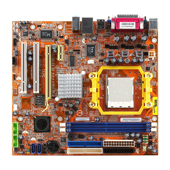
Page 11: Motherboard Layout
Chapter 1 Product Introduction Motherboard Layout 27 26 14. Speaker Connector 1. Front Audio Connector 15. IDE Connectors 2. CD_IN Connector 3. AUX_IN Connector (optional) 16. FDD Connector 17. 24-pin ATX Power Connector 4. S/PDIF OUT Connector 5. System Fan Connector 18. -
Page 12: Rear I/O Ports
Chapter 1 Product Introduction Rear I/O Ports This motherboard provides the ports as below: For -6 models Parallel Port 1394 Connector Connector (Printer Port) Line-in jack PS/2 Mouse Connector Line-out jack PS/2 Keyboard Microphone jack Connector Serial Port VGA Port USB 2.0 Ports (COM1) For -8 models... - Page 13 Chapter 2 Installation Instructions Chapter This chapter introduces the hardware installation process, including the installation of the CPU and memory. It also addresses the connection of your power supply, connec- tion of hard drive and floppy drive data cables, and setting up various other feature of the motherboard.
-
Page 14: Installation Of Cpu
Chapter 2 Installation Instructions This motherboard Supports socket AM2 for AMD ® Athlon 64 FX / Athlon 64 X2 Dual-Core / Athlon 64/ Sempron processors. For the detailed CPU support list on this motherboard, please visit the website: http://www.foxconnchannel.com Attention: The CPU pins must be properly aligned with the holes in the socket, otherwise the CPU may be damaged. -
Page 15: Memory
Chapter 2 Installation Instructions Memory This motherboard includes two 240-pin slots for DDRII. You must install at least one memory module to ensure normal operation. Installation of DDR Memory 1. There is only one gap in the center of the DIMM socket, and the memory module can be fixed in one direction only. -
Page 16: Power Supply
Chapter 2 Installation Instructions Power Supply This motherboard uses an ATX power supply. In order to avoid damaging any devices, make sure that they have been installed properly prior to connecting the power supply. 24-pin ATX power connector 24-pin ATX power connector: PWR1 RSVD PS-ON PWR1 is the ATX power supply connector. -
Page 17: Other Connectors
Chapter 2 Installation Instructions Other Connectors This motherboard includes connectors for FDD devices, IDE devices, Serial ATA devices, USB devices, IR module, and others. FDD Connector: FLOPPY This motherboard includes a standard FDD connector, supporting 360K, 720K, 1.2M, 1.44M, and 2.88M FDDs. HDD Connectors: PIDE &... -
Page 18: Installation Instructions
Chapter 2 Installation Instructions Front Panel Connector: FP1 This motherboard includes one connector for connecting the front panel switch and LED indicators. Hard Disk LED Connector (HDD_LED) The connector connects to the case’s IDE indicator LED indicating the activity status of IDE hard disk. Reset Switch (RESET) Attach the connector to the Reset switch on the front panel of the case;... - Page 19 Chapter 2 Installation Instructions IrDA Header: IR This connector supports wireless transmitting E m p t y and receiving device. Before using this function, configure the settings of IR Address, IR Mode and IR IRQ from the “Integrated Peripherals” section of the CMOS Setup. USB Headers: F_USB1, F_USB2 Besides four USB ports on the rear panel, the series of motherboards also have two 10-pin...
- Page 20 Chapter 2 Installation Instructions Front Audio Connector: F_AUDIO The audio connector provides two kinds of audio output choices: the Front Audio, the Rear Audio. Their priority is sequenced from high to low (Front MIC_IN MIC_GND MIC_PWR +5VA Audio to Rear Audio). If headphones are plugged AUD_OUT_R AUD_RET_R into the front panel of the chassis (using the Front...
-
Page 21: Expansion Slots
Chapter 2 Installation Instructions Expansion Slots This motherboard includes two 32-bit master PCI bus slots, one PCI Express x1 slot,one PCI Express x16 slot. PCI Slots The expansion cards can be installed in the two PCI slots. W hen you install or take out such cards, you must make sure that the power plug has been pulled out. -
Page 22: Jumpers
Chapter 2 Installation Instructions Jumpers The users can change the jumper settings on this motherboard if needed. This section explains how to use the various functions of this motherboard by changing the jumper settings. Users should read the following contents carefully prior to modifying any jumper settings. - Page 23 Chapter 3 BIOS Description Chapter This chapter tells how to change system settings through the BIOS Setup menus. Detailed descriptions of the BIOS param- eters are also provided. You have to run the Setup Program when the following cases occur: 1.
-
Page 24: Enter Bios Setup
Chapter 3 BIOS Description Enter BIOS Setup The BIOS is the communication bridge between hardware and software, correctly setting up the BIOS parameters is critical to maintain optimal system performance. Power on the computer, when the following message briefly appears at the bottom of the screen during the POST (Power On Self Test), press <Del>... - Page 25 Chapter 3 BIOS Description Central Control Unit The special features can be set up through this menu. Advanced BIOS Features The advanced system features can be set up through this menu. Advanced Chipset Features The values for the chipset can be changed through this menu, and the sys- tem performance can be optimized.
-
Page 26: Standard Cmos Features
Chapter 3 BIOS Description Standard CMOS Features This sub-menu is used to set up the standard CMOS features, such as the date, time, HDD model and so on. Use the arrow keys select the item to set up, and then use the <PgUp> or <PgDn> keys to choose the setting values. Standard CMOS Features Menu Date This option allows you to set the desired date (usually as the current day) with... - Page 27 Chapter 3 BIOS Description Award(Phoenix)BIOS can support 3 HDD modes:CHS, LBA and Large or Auto mode. For HDD<528MB For HDD>528MB & supporting LBA (Logical Block Addressing) Large For HDD>528MB but not supporting LBA Auto Recommended mode Floppy Drive A This option allows you to select the kind of FDD to be installed, including “None”, [360K, 5.25 in], [1.2M, 5.25 in], [720K, 3.5 in], [1.44M, 3.5 in] and [2.88 M, 3.5 in].
- Page 28 Chapter 3 BIOS Description Memory This is a Display-Only Category, determined by POST (Power On Self Test) of the BIOS. Base Memory The BIOS POST will determine the amount of base (or conventional) memory installed in the system. Extended Memory The BIOS determines how much extended memory is present during the POST.
-
Page 29: Central Control Unit
Chapter 3 BIOS Description Central Control Unit Central Control Unit Menu [Smart BIOS] vSmart Power LED Smart debug LED function within power LED. Enable this function, the power LED status can show the system status of POST process. System Status Power LED Status Normal No CPU Fan... - Page 30 Chapter 3 BIOS Description vSpread Spectrum If you enable spread spectrum, it can significantly reduce the EMI (Electro- Magnetic Interference) generated by the system. The setting values are Disabled and Enabled. vCPU Clock This option is used to set the CPU clock. vAsync AGP/PCI Clock This option is used to set the Async AGP/PCI Clock.
-
Page 31: Advanced Bios Features
Chapter 3 BIOS Description Advanced BIOS Features Advanced BIOS Features Menu vHard Disk Boot Priority This option is used to select the priority for HDD startup. After pressing <Enter>, you can select the HDD using the <PageUp>/<PageDn> or Up/ Down arrow keys, and change the HDD priority using <+> or <->; you can exit this menu by pressing <Esc>. - Page 32 Chapter 3 BIOS Description vFirst/Second/Third Boot Device This option allows you to set the boot device’s sequence. vBoot From Other Device W ith this function set to enable, the system will boot from some other de- vices if the first/second/third boot devices failed. The setting values are: Dis- abled and Enabled.
- Page 33 Chapter 3 BIOS Description vOS Select For DRAM > 64MB This option is only required if you have installed more than 64 MB of memory and you are running the OS/2 operating system. Otherwise, leave this option at the default. vReport No FDD For WIN 95 If you are using the Windows 95 and running a system with on floppy drive.
-
Page 34: Advanced Chipset Features
Chapter 3 BIOS Description Advanced Chipset Features Advanced Chipset Features Menu vAGP & P2P Bridge Control Press enter to set the items about AGP & P2P bridge. vDRAM Configuration Press enter to set the items about DRAM Configuration. vLDT & PCI Bus Control Press enter to set the items about CPU &... - Page 35 Chapter 3 BIOS Description AGP & P2P Bridge Control Menu vAGP Aperture Size This option defines the size of the aperture if you use an AGP graphics adapter. The aperture is a portion of the PCI memory address range dedicated for graphic memory address space.
- Page 36 Chapter 3 BIOS Description vTV Output Connector This option is used to set the TV Output Connector. vAnti-DotCrawl This option is used to set the Anti-DotCrawl. DRAM Configuration Menu vCurrent FSB Frequency This option is used to set the Current FSB Frequency. vCurrent DRAM Frequency This option is used to set the Current DRAM Frequency.
- Page 37 Chapter 3 BIOS Description vMemory hole Remapping This item is used to enable or disable the Memory hole Remapping. vBottom of UMA DRAM [31:24] This item is used to set Bottom of UMA DRAM [31:24]. LDT & PCI Bus Control Menu vUpstream/Downstream LDT Bus Width This option allows you to select upstream/downstream LDT(Lightning Data Transport) bus width.
-
Page 38: Integrated Peripherals
Chapter 3 BIOS Description Integrated Peripherals Integrated Peripherals Menu vVIA OnChip IDE Function Setup Press enter to VIA OnChip IDE Function Setup. vVIA OnChip PCI Setup Press enter to VIA OnChip PCI Setup. vVIA SuperIO Device Press enter to set VIA SuperIO device. vOn board Lan Device This option is used to set On board Lan Device. - Page 39 Chapter 3 BIOS Description VIA OnChip IDE Device Menu OnChip SATA This option is used to enable or disable onchip SATA. vSATA Mode This option is used to select SATA mode. vIDE DMA transfer access This option is used to enable or disable IDE DMA transfer access. vOnChip IDE Channel 0/1 The integrated peripheral controller contains an IDE interface with support for two IDE channels.
- Page 40 Chapter 3 BIOS Description OnChip PCI Device Menu vVIA-3058 AC’97 Audio “Auto” allows the motherboard’s BIOS to detect whether you’re using any audio devices. If so, the onboard audio controller will be enabled. If not, the onboard audio controller will be disabled. If you want to use different control- ler cards to connect audio connectors, set the option to “Disabled”.
- Page 41 Chapter 3 BIOS Description SuperIO Device Menu vOnboard FDC Controller This option is used to set whether the Onboard FDC Controller is enabled. The available setting values are: Disabled and Enabled. vOnboard Serial Port1/2 This option is used to assign the I/O address and interrupt request (IRQ) for the onboard serial port 1/2.
-
Page 42: Power Management Setup
Chapter 3 BIOS Description Power Management Setup Power Management Setup Menu vACPI function ACPI stands for “Advanced Configuration and Power Interface”. ACPI is a standard that defines power and configuration management interfaces be- tween an operating system and the BIOS. In other words, it is a standard that describes how computer components work together to manage system hardware. - Page 43 Chapter 3 BIOS Description vVideo Off Option This option is used to set video off option. vVideo Off Method This option is used to define the video off method. “Blank Screen” mode means that after the computer enters into power saving mode, only the monitor will close, however, the vertical and horizontal scanning movement of the screen continues.
- Page 44 Chapter 3 BIOS Description IRQ/Event Activity Detect Menu vPS2KB Wakeup Select This option is used to select which action will wake up PS/2 keyboard from S3 /S4/S5 staus. Use <PgUp> or <PgDn> to select the desired item. The setting values are: Hot key, Password. vPS2KB Wakeup from S3/S4/S5 This option is used to select which hotkey will wake up by PS/2 keyboard from S3/S4/S5 staus or disable it.
- Page 45 Chapter 3 BIOS Description vRTC Alarm Resume This option is used to set alarm to power on the system by the date (1-31) or time (hh:mm:ss). The setting values are: Disabled and Enabled. vDate (of Month) This option is used to set the timing for the start-up day of the month. The setting values contain 0 –...
- Page 46 Chapter 3 BIOS Description IRQs Activity Monitoring Menu Primary INTR Selecting “ON” will cause the system to wake up from power saving modes if activity is detected from any enabled IRQ channels. The setting values are: ON and OFF. vIRQ3 (COM2) This option is used to enable or disable IRQ3 (COM2) activity monitoring.
- Page 47 Chapter 3 BIOS Description vIRQ10 (Reserved) This option is used to enable or disable IRQ10 (Reserved) activity monitoring. The setting values are: Disabled and Enabled. vIRQ11 (Reserved) This option is used to enable or disable IRQ11 (Reserved) activity monitoring. The setting values are: Disabled and Enabled. vIRQ12 (PS/2 Mouse) This option is used to enable or disable IRQ12 (PS/2 Mouse) activity monitoring.
-
Page 48: Pnp/Pci Configurations
Chapter 3 BIOS Description PnP/PCI Configurations PnP/PCI Configurations Menu PNP OS Installed Set this field to “Yes” if you are running W indows 95, which is PnP compatible. It is recommended to keep the default setting. The setting values are: No, Yes. Reset Configuration Data This option is used to set whether the system is permitted to automatically distribute IRQ DMA and I/O addresses when each time that the machine is... -
Page 49: Pc Health Status
Chapter 3 BIOS Description PC Health Status PC Health Status Menu vShutdown Temperature This option is used to set the system temperature upper limit. W hen the temperature exceeds the setting value, the motherboard will automatically cut off power to the computer. vWarning Temperature This option is used to enable or disable Warning Temperature. - Page 50 Chapter 3 BIOS Description vCPU Fan High Set Point This option is used to set the CPU Fan High Set Point vCPU Fan Intel PWM Value This option is used to set the CPU Fan Intel PW M Value. vCPU Fan Slope(PWM/ This option is used to set the CPU Fan Slope(PWM/...
-
Page 51: Load Fail-Safe Defaults
Chapter 3 BIOS Description Load Fail-Safe Defaults Press <Enter> to select this option. A dialogue box will pop up that allows you to load the default BIOS settings. Select <Y> and then press <Enter> to load the defaults. Select <N> and press <Enter> to exit without loading. The defaults set by BIOS set the basic system functions in order to ensure system stability. -
Page 52: Save & Exit Setup
Chapter 3 BIOS Description If you do not want to set a password, just press <Enter> when prompted to enter a password, and in the screen the following message will appear. If no password is keyed in, any user can enter the system and view/modify the CMOS settings. Password Disabled!!! Press any key to continue …... - Page 53 Chapter 4 Driver CD Introduction Chapter The utility CD that came with the motherboard contains use- ful software and several utility drivers that enhance the motherboard features. This chapter includes the following information: Utility CD content Start to install drivers...
-
Page 54: Utility Cd Content
Chapter 4 Driver CD Introduction Utility CD content This motherboard comes with one Utility CD. To begin using the CD, simply insert the CD into your CD-ROM drive. The CD will automatically displays the main menu screen. 1. Install Driver Using this choice, you can install all the drivers for your motherboard. - Page 55 Chapter 4 Driver CD Introduction Start to Install divers Select <Application Driver>and click to enter the install driver screen. You can select the driver that you want to install and begin the setup steps.
- Page 56 Chapter 4 Driver CD Introduction Chapter This chapter will introduce how to use attached software. This chapter provides the following information: TIGER ONE Fox LiveUpdate...
-
Page 57: Tiger One
Chapter 5 Directions for Bundled Software TIGER ONE TIGER ONE is a powerful utility for easily modifying system settings. It also allows users to monitor various temperature values, voltage values, frequency and fan speed at any time. With TIGER ONE, you can -Modify system performance settings, such as bus speeds, CPU voltages, fan speed, and other system performance options that are supported by the BIOS... - Page 58 Click this button to configurate the parameters for the program. It determines which items will be shown in shorten mode. Homepage Click this button to visit Foxconn motherboard website. 2. CPU Page - CPU Control This page lets you select and run the TIGER ONE developed benchmarks to determine the current performance level of the system.
- Page 59 Chapter 5 Directions for Bundled Software Go to CPU page Close this page Ajust by manual Reset the Apply the changes changes Select the different benchmarks 3. Freq. Page - Frequency Control This page lets you set memory and PCI Express frequency by manual. Go to Freq.
- Page 60 Chapter 5 Directions for Bundled Software 4.1 Limit Setting - CPU Temp. This page lets you to set CPU high limit temperature and enable the alert function. Show current CPU Go to Adjust page temperature value Enable alert function when the CPU temperature is higher than high limit value Show current high...
- Page 61 Chapter 5 Directions for Bundled Software 4.3 Limit Setting - CPU Fan This page lets you to set CPU fan low limit rpm and enable the alert function. Show current CPU fan rpm value Enable alert function when the CPU fan rev is lower than low limit rpm value Show current low limit...
- Page 62 Chapter 5 Directions for Bundled Software 5. Fan Page - Fan Control This page lets you enable smart Fan function or set fan speed by manual. Go to Fan page Enable or disable smart fan function Set fan speed by dragging the lever Apply the changes Reset the changes...
-
Page 63: Fox Liveupdate
Chapter 5 Directions for Bundled Software Fox LiveUpdate Fox LiveUpdate is a useful utility for backuping and updating the system BIOS, drivers and utilities by local or online. Supported Operating Systems: -W indows 2000 -Windows XP (32-bit and 64-bit) -W indows 2003 (32-bit and 64-bit) Using Fox LiveUpdate: 1.1 Local Update - BIOS Info. - Page 64 Chapter 5 Directions for Bundled Software 1.2 Local Update - Backup This page lets you backup your system BIOS. Click “Backup”, then give a name. Click “Save” to finish the backup operation. Key in a BIOS name Click here 1.3 Local Update - Update This page lets you update your system BIOS from Internet.
- Page 65 Chapter 5 Directions for Bundled Software 2.1 Online Update - Update BIOS This page lets you update your system BIOS from Internet. Click “start”, it will search the new BIOS from Internet. Then follow the wizard to finish the update operation.
- Page 66 Chapter 5 Directions for Bundled Software 2.2 Online Update - Update Driver This page lets you update your system drivers from Internet. Click “start”, it will search the new drivers from Internet. Then follow the wizard to finish the update operation.
- Page 67 Chapter 5 Directions for Bundled Software 2.3 Online Update - Update Utility This page lets you update utilities from Internet. Click “start”, it will search the new utilities from Internet. Then follow the wizard to finish the update operation. Click here Current information Search new utilities from Internet...
- Page 68 Chapter 5 Directions for Bundled Software 3.1 Configure - option This page lets you set auto search options. After your setting, the utility will start searching and related information will show on the task bar. Click here Set auto search options Select search which kind of versions...
- Page 69 Chapter 5 Directions for Bundled Software 3.2 Configure - System This page lets you set the backup BIOS location and change different skin of the utility. Click here Set the location of download files or auto backup BIOS Select different skin of the software Apply the changes Reset to default value...