Table of Contents
Advertisement
Advertisement
Table of Contents

Related Manuals for Foxconn Rattler


Summary of Contents for Foxconn Rattler
- Page 1 Rattler Series Motherboard User’s Manual...
- Page 2 Statement: This manual is the intellectual property of Foxconn, Inc. Although the information in this manual may be changed or modified at any time, Foxconn does not obligate itself to inform the user of these changes. Trademark: All trademarks are the property of their respective owners.
-
Page 3: Declaration Of Conformity
66 , CHUNG SHAN RD., TU-CHENG INDUSTRIAL DISTRICT, TAIPEI HSIEN, TAIWAN, R.O.C. declares that the product Motherboard Rattler / Rattler GTI is in conformity with (reference to the specification under which conformity is declared in accordance with 89/336 EEC-EMC Directive) ■... - Page 4 Declaration of conformity Trade Name: FOXCONN Model Name: Rattler / Rattler GTI Responsible Party: PCE Industry Inc. Address: 458 E. Lambert Rd. Fullerton, CA 92835 Telephone: 714-738-8868 Facsimile: 714-738-8838 Equipment Classification: FCC Class B Subassembly Type of Product: Motherboard Manufacturer:...
-
Page 5: Installation Precautions
Installation Precautions ■ Electrostatic discharge (ESD) is the sudden and momentary electric current that flows between two objects at different electrical potentials. Normally it comes out as a spark which will quickly damage your electronic equipment. Please wear an electrostatic discharge (ESD) wrist strap when handling components such as a motherboard, CPU or memory. -
Page 6: Table Of Contents
TAble of CoNTeNTS Chapter 1 Product Introduction Product Specifications ................2 Layout.......................4 Back Panel Connectors ................5 Chapter 2 Hardware Install Install the CPU and CPU Cooler ..............8 Install the Memory .................. 11 Install an Expansion Card ..............13 Install other Internal Connectors ............14 Jumpers ....................18 OnBoard Button..................19 OnBoard Debug LED ................20... - Page 7 BIOS Configuration ................66 Create RAID in BIOS................66 Install a New Windows XP ..............95 Existing Windows XP with RAID built as data storage ......99 Appendix - Crossfire Technology ............103 Technical Support : Support Website : http://www.foxconnchannel.com Support Website : http://www.foxconnsupport.com Worldwide online contact Support : http://www.foxconnsupport.com/inquiry.aspx CPU Support list : http://www.foxconnsupport.com/cpusupportlist.aspx...
- Page 8 Thank you for buying Foxconn Rattler Series motherboard. Foxconn products are engineered to maximize computing power, providing only what you need for break-through performance. With advanced overclocking capability and a range of connectivity features for today multi-media computing requirements, Rattler/Rattler GTI enables you to unleash more power from your computer.
-
Page 9: Product Specifications
3 x System fan headers (3-pin) 2 x Fan headers (3-pin) 3 x USB 2.0 connectors (supporting 6 x USB devices) 1 x 1394a connector (Only for Rattler, controlled by VIA VT6308S ) 1 x Front panel connector Continued on the next page... - Page 10 1 x Optical S/PDIF out connector 1 x Coaxial S/PDIF out connector 1 x 1394a port 2 x LAN ports 2 x USB 3.0 ports 2 x eSATA ports (Only for Rattler) 8-channel Audio ports Hardware Monitor System voltage detection CPU/System temperature detection...
-
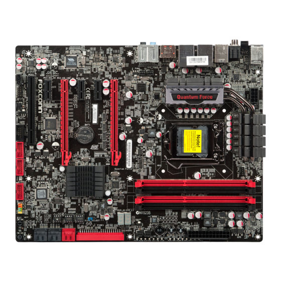
Page 11: Layout
1-2 layout 22 23 25 26 1. 8-pin ATX 12V Power Connector 16. Reset Button 2. SPDIF-OUT2 Connector 17. Power On Button 3. SYS_FAN3 Header 18. SATA Connectors 4. FAN1 Header 19. BIOS_Select Jumper 5. PCI Express x16 Slots 20. IDE Connector 6. -
Page 12: Back Panel Connectors
1-3 back Panel Connectors Optical S/PDIF Out External PS/2 Port LAN Ports Coaxial 1394a Port SATA Ports Line Out S/PDIF Out Line In Rear Speaker Subwoofer Side Speaker Microphone In Clear CMOS Button Audio Ports USB Ports 1. PS/2 Keyboard Port Use this port (purple) to connect a PS/2 keyboard. - Page 13 7. external SATA Ports (only for Rattler) To connect external SATA device(s) to your system by expanding the internal SATA port(s) to the chassis back panel. External SATA device shall provide power by its own. 8. Audio Ports For the definition of each audio port, please refer to the table below :...
- Page 14 This chapter introduces the hardware installation process, including the installation of the CPU, memory, power supply, slots, pin headers and the mounting of jumpers. Caution should be exercised during the installation of these modules. Please refer to the motherboard layout prior to any installation and read the contents in this chapter carefully.
-
Page 15: Install The Cpu And Cpu Cooler
2-1 Install the CPU and CPU Cooler Read the following guidelines before you begin to install the CPU : ■ Make sure that the motherboard supports the CPU. ■ Always turn off the computer and unplug the power cord from the power supply before installing the CPU to prevent hardware damage. - Page 16 Follow the steps to install the CPU onto the CPU socket : Before installing the CPU, make sure to turn off the computer and unplug the power cord from the power outlet to prevent damage to the CPU. 1. Release the CPU socket lever. 2.
-
Page 17: Install The Cpu Cooler
Install the CPU Cooler Follow the steps below to correctly install the CPU cooler on the motherboard. 1. Apply and spread an even thermal 2. Place the four bolts of the CPU grease on the surface of CPU. cooler to the holes of the motherboard, push them straight down from the top, and the bolts will be fastened on the motherboard. -
Page 18: Install The Memory
2-2 Install the Memory Read the following guidelines before you begin to install the memory : ■ Make sure that the motherboard supports the memory. It is recommended that memory of the same capacity, brand, speed, and chips be used. ■... -
Page 19: Installing A Memory
Installing a Memory ■ Before installing a memory module, make sure to turn off the computer and unplug the power cord from the power outlet to prevent damage to the memory module. Be sure to install DDR3 DIMMs on this motherboard. Notch If you take a look at front side of memory module, it has asymmetric pin counts on both sides separated by a notch in the middle, so it can only fit in one direction. -
Page 20: Install An Expansion Card
2-3 Install an expansion Card ■ Make sure the motherboard supports the expansion card. Carefully read the manual that came with your expansion card. ■ Always turn off the computer and unplug the power cord from the power outlet before installing an expansion card to prevent hardware damage. -
Page 21: Install Other Internal Connectors
2-4 Install other Internal Connectors Power Connectors This motherboard uses an ATX power supply. In order not to damage any device, make sure all the devices have been installed properly before applying the power supply. 24-pin ATX Power Connector : PWR1 PWR1 is the ATX power supply connector. - Page 22 Connect a 4-pin power plug We recommend you using an 8-pin ATX 12V power supply. If you are using a 4-pin power supply, you need to align the ATX power connector according to the picture on the right. CD_L GND CD_R Audio Connector : CD_IN CD_IN is a Sony standard audio connector, it can be connected to a CD/DVD-ROM drive through a...
- Page 23 front Panel Connector : fP1 This motherboard includes one connector for connecting the front panel switch and LED Indicators. HDD-LED PWR-LED Hard Disk leD Connector (HDD-leD) RESET-SW PWR-SW Connect to the chassis front panel IDE indicator LED. It EMPTY indicates the active status of the hard disks. This 2-pin connector is directional with +/- sign.
- Page 24 S/PDIf Connector : SPDIf_oUT3 The connector is used for S/PDIF output. SPDIF_OUT SPDIF_OUT3 fan Connectors : CPU_fAN, fAN1/2, SYS_fAN1/2/3 There are six main fan headers on this motherboard. The fan speed can be controlled and monitored in “Quantum BIOS” section of the BIOS Setup. These fans can be automatically turned off after the system enters S3, S4 and S5 sleeping states.
-
Page 25: Jumpers
2-5 Jumpers For some features needed, users can change the jumper settings on this motherboard to modify them. This section explains how to use the various functions of this motherboard by changing the jumper settings. Users should read the following content carefully prior to modifying any jumper setting. Description of Jumpers 1. -
Page 26: Onboard Button
bIoS Select Jumper: bIoS_SeleCT The jumper is used to select a BIOS ROM to boot from. You can refer to the following table for reference. How to recover BIOS When one of BIOS has been damaged, you can use another (Default) workable BIOS to boot to DOS. -
Page 27: Onboard Debug Led
oC Switch button: oC_SW1/2/3 You could press the three buttons to adjust the CPU clock directly, without to enter BIOS setup or any soft- ware. This process will not use any system resource, so there is no effect to the system performance. ■... - Page 28 This chapter tells how to change system settings through the BIOS Setup menus. Detailed descriptions of the BIOS parameters are also provided. You have to run the Setup Program when the following cases occur : 1. An error message appears on the screen during the system Power On Self Test (POST) process.
-
Page 29: Enter Bios Setup
enter bIoS Setup The BIOS is the communication bridge between hardware and software, correctly setting up the BIOS parameters is critical to maintain optimal system performance. Power on the computer, when the message "Press TAb to show PoST screen, Del to enter SeTUP" appears at the bottom of the screen, you can press <DEL>... -
Page 30: Main
Set the Date. Use Tab to BIOS Vendor American Megatrends switch between Date elements. BIOS Build Date 12/09/2010 09:44:32 System BIOS Version Model Name Rattler CPU Information Genuine Intel(R) CPU 0 @ 3.00GHz Processor Stepping 206a3 Microcode Revision Processor Cores Memory Information →... - Page 31 Only). Month—month from 1 to 12. Date—date from 1 to 31. Year—year, set up by users. Use [ENTER], [TAB] or [SHIFT-TAB] to select a field. Use [+] or [-] to input the value. ► System Time This item allows you to configure the desired time. Use [ENTER], [TAB] or [SHIFT-TAB] to select a field.
-
Page 32: Advanced
Advanced Aptio Setup Utility - Copyright (C) 2010 American Megatrends, Inc. Main Advanced Chipset Boot Power Health Security Save & Exit Advanced Enable or Disable Boot Option Legacy OpROM Support Launch LAN 1 PXE OpROM [Disabled] for Legacy Network Devices. Launch LAN 2 PXE OpROM [Disabled] Launch Storage OpROM... -
Page 33: Pci Subsystem Settings
PCI Subsystem Settings Aptio Setup Utility - Copyright (C) 2010 American Megatrends, Inc. Advanced PCI Bus Driver Version V 2.03.00 In case of multiple Option PCI ROM Priority [EFI Compatible ROM] ROMs(Legacy and EFI Compatible), specifies what PCI Common Settings PCI Option ROM to launch. -
Page 34: Maximum Read Request
► Maximum Read Request This item is used to set the maximum read request size of PCI Express Device, or you can set [Auto] to allow system BIOS to select the value. PCI Express Link Settings ► ASPM Support You can set the ASPM level here: [Force L0]: Force all links to L0 state. -
Page 35: Onboard Device
This item determines whether to invoke VGA BIOS post on S3/STR resume. ► S4 and S5 Wake-Up Power Supply when you select [Disabled], only the power button can wake up the system in S4 and S5 state. ► PS2 KB Wake-Up From S1 and S3 This item is used to enable or disable PS2 key board wake up from S1 and S3 state. -
Page 36: Sata Configuration
SATA Configuration Aptio Setup Utility - Copyright (C) 2010 American Megatrends, Inc. Advanced (1) IDE Mode. (2) AHCI Mode SATA Configuration (3) RAID Mode. SATA Mode [AHCI Mode] Aggressive Link Power Management [Enabled] SATA Port 0 Not Present Staggered Spin-up [Disabled] External SATA Port [Disabled]... -
Page 37: Usb Configuration
We will use SATA Port 0 as an example to explain the SATA ports features: ► SATA Port 0 This item shows the SATA device information connected to Port 0. ► Staggered Spin-up (Appears when “SATA Mode” is set to [AHCI Mode]) This item is used to select if the SATA controller supports staggered spin-up on its ports, for use in balancing power spikes. - Page 38 ► USB Transfer time-out This item is used to select a time-out value for Control,Bulk and Interrupt Transfers. Default value is [20 sec]. ► Device reset time-out This item is used to select the USB mass storage device start unit command time-out. Default value is [20 sec].
-
Page 39: Chipset
Chipset Aptio Setup Utility - Copyright (C) 2010 American Megatrends, Inc. Main Advanced Chipset Boot Power Health Security Save & Exit Chipset ►North Bridge North Bridge Parameters ►South Bridge ►ME Subsystem → ←: Select Screen ↑ ↓: Select Item Enter: Select +/-: Change Opt. -
Page 40: South Bridge
► Low MMIO Align This item is used to align resources to low MMIO. Default option is: [1024M]. ► DMI Gen2 This item is used to enable or disable the DMI Gen2. ► VT-d This item is used to enable or disable the VT-d feature. Intel Virtualization Technology for ®... -
Page 41: Audio Configuration
► SlP_S4 Assertion Stretch enable This item is used to enable or disable the SLP-S4 assertion strech. ► SLP-S4 Assertion Width This item is used to set the SLP_S4 assertion width. Audio Configuration ► Azalia HD Audio This item is used to enable or disable the Azalia HD audio. High Precision Event Timer Configuration ►... -
Page 42: All Usb Devices
USB Configuration Aptio Setup Utility - Copyright (C) 2010 American Megatrends, Inc. Chipset USB Configuration Enabled/Disabled All USB Devices All USB Devices [Enabled] EHCI Controller 1 [Enabled] EHCI Controller 2 [Enabled] USB Port 0 [Enabled] USB Port 1 [Enabled] USB Port 2 [Enabled] USB Port 3 [Enabled]... -
Page 43: Intel Me Subsystem Configuration
Me Subsystem Aptio Setup Utility - Copyright (C) 2010 American Megatrends, Inc. Chipset ME Subsystem Help Intel ME Subsystem Configuration ME Version ME System [Enabled] ME Temporary Disable [Disabled] End of Post Message [Enabled] → ←: Select Screen ↑ ↓: Select Item Enter: Select +/-: Change Opt. -
Page 44: Boot
boot Aptio Setup Utility - Copyright (C) 2010 American Megatrends, Inc. Main Advanced Chipset Boot Security Save & Exit Quantum BIOS Boot Boot Configuration Number of seconds to wait for Setup Prompt Timeout setup activation key. Bootup Numlock State [On] 65535(0xFFFF) means indefinite waiting. -
Page 45: Security
Security Aptio Setup Utility - Copyright (C) 2010 American Megatrends, Inc. Main Advanced Chipset Boot Security Save & Exit Quantum BIOS Security Set Setup Administrator Password Password Description If ONLY the Administrator’s password is set, then this only limits access to Setup and is only asked for when entering Setup. -
Page 46: Save & Exit
Save & Exit Aptio Setup Utility - Copyright (C) 2010 American Megatrends, Inc. Main Advanced Chipset Boot Security Save & Exit Quantum BIOS Save & Exit Exit system setup after saving Save Changes and Exit the changes. Discard Changes and Exit Save Changes and Reset Discard Changes and Reset Save Options... -
Page 47: Boot Override
Select <Yes> and then press <Enter> to load the defaults. Select <No> and press <Enter>, it will not load. By this default, BIOS have set the optimal performance parameters of system to improve the performances of system components. But if the optimal performance parameters to be set cannot be supported by your hardware devices (for example, too many expansion cards were installed), the system might fail to work. -
Page 48: Quantum Bios
Quantum bIoS Aptio Setup Utility - Copyright (C) 2010 American Megatrends, Inc. Main Advanced Chipset Boot Security Save & Exit Quantum BIOS Quantum BIOS ► CPU Configuration CPU Configuration Parameters. ► Memory Settings ► All Voltage Settings ► OC Gear ►... -
Page 49: Cpu Configuration
CPU Configuration Aptio Setup Utility - Copyright (C) 2010 American Megatrends, Inc. Quantum BIOS Quantum BIOS Enabled for Windows XP and Linux(OS CPU Configuration optimized for Hyper-Threading Technology) and Disabled for other Genuine Intel(R) CPU 0 @ 3.00GHz OS(OS not optimized for Hyper- Processor Stepping 206a3 Threading Technology). - Page 50 ► Adjacent Cache Line Prefetch (Appears only when CPU supports) The processor has a hardware adjacent cache line prefetch mechanism that automatically fetches an extra 64-byte cache line whenever the processor requests for a 64-byte cache line. This reduces cache latency by making the next cache line immediately available if the processor requires it as well.
- Page 51 Memory Settings Aptio Setup Utility - Copyright (C) 2010 American Megatrends, Inc. Quantum BIOS Cas Latency, Range 3-15. Memory Timing Configuration CAS# Latency(tCL) Row Precharge Time(tRP) RAS# to CAS# Delay(tRCD) RAS# Active Time(tRAS) Write Recovery Time(tWR) Row Refresh Cycle Time(tRFC) Write to Read Delay(tWTR) Active to Active Delay(tRRD) Read CAS# Precharege(tRTP)
-
Page 52: Cpu Pll Voltage
All Voltage Settings Aptio Setup Utility - Copyright (C) 2010 American Megatrends, Inc. Quantum BIOS CPU Core Power Voltage setting. CPU Core Voltage Mode [Standard Mode] CPU Voltage Offset(1/10000 Volt) CPU VTT (Uncore) Voltage [Default] CPU PLL Voltage [1.80V] CPU VccSA Voltage [Default] DRAM Voltage [1.598V]... - Page 53 oC Gear Aptio Setup Utility - Copyright (C) 2010 American Megatrends, Inc. Quantum BIOS You can backup your BIOS setting to slot Backup Slot [Not Use It] or restore your backup setting to BIOS or erase your backup slot. → ←: Select Screen ↑...
-
Page 54: Hardware Monitor
Hardware Monitor Aptio Setup Utility - Copyright (C) 2010 American Megatrends, Inc. Quantum BIOS Smart Fan, Full Speed, By Duty-Cycle, CPU_FAN1 Control [Smart Fan] Stop Fan. CPU_FAN1 Speed : 2501 RPM SYS_FAN1 Control [Smart Fan] SYS_FAN1 Speed : N/A SYS_FAN2 Control [Smart Fan] SYS_FAN2 Speed : N/A... - Page 55 The utility CD that came with the motherboard contains useful software and several utility drivers that enhance the mother- board features. This chapter includes the following information: ■ Utility CD content ■ Install driver and utility ■ AEGIS PANEL ■ FOX LOGO ■...
-
Page 56: Utility Cd Content
Utility CD content This motherboard comes with one DVD, after installing the Operating System, you can simply put it into your DVD-ROM drive, and the main menu will be displayed on your PC screen to guide you how to install. 1. -
Page 57: Install Driver And Utility
Step by Step Automatic Installation by One Click Drop to System Tray Exit the program Click to visit Select to Install Select to Browse CD View the Utility Help files Foxconn's Utilities Install Drivers website Choose the items you want to Install... -
Page 58: Install Utility
2. Install Utility Use these options to install additional software programs. 3. Utility Help Click this button to view the utility(AEGIS PANEL,FOX LOGO, FOX DMI, etc.) help manual. -
Page 59: Aegis Panel
AeGIS PANel Aegis Panel, is a Windows innovation tool which provides settings of OC gear, overclocking, fan control and alarm function. It also displays system monitoring information such as fan speed, temperature, voltage and CPU clock etc.. The powerful features are: HW Monitor(Hardware Monitor Information) Overclocking OC Gear (Optional) -
Page 60: Hw Monitor
2. HW Monitor Click on "HW Monitor" icon , its panel appears. By moving the mouse on the voltage icon, it will display voltage information. Move the mouse on fan or temperature icon will show relative information accordingly. Voltage icon Fan icon Temperature icon 2.1 HW Monitor - Voltage... - Page 61 2.2 HW Monitor - fan Move the mouse on the fan icon , its menu appears. Click on the fan icon to get into the fan setting menu. It allows you to set the low/high limits of the CPU, NB and System fan speeds, and to enable the alert function.
-
Page 62: Overclocking
3. Overclocking Click "Overclocking" icon to enter the overclok setting menu. It allows you to adjust CPU clock, and to change the voltages of CPU, chipset and memory. After you set the values, click [Apply] button to apply it. Click these buttons to adjust the CPU clock Click these buttons to adjust the CPU voltages... -
Page 63: Fox Logo
foX loGo FOX LOGO is a simple and useful utility to backup, change and delete the boot time Logo. The boot Logo is the image that appears on screen during POST (Power-On Self-Test). You can prepare a JPG image (1024x768) file, then use FOX LOGO to open it and change the boot time Logo. -
Page 64: Fox Dmi
foX DMI FOX DMI is a full Desktop Management Interface viewer, and it provides three DMI data formats : Report, Data Fields and Memory Dump. With DMI information, system maker can easily analyze and troubleshoot your mother- board if there is any problem occurred. Supporting Operating Systems : ■... -
Page 65: Browser Configuration Utility
Browser Configuration Utility Browser Configuration Utility is a browser search engine of Yahoo. We provide it to you for various choice. Supporting Operating Systems : ■ Windows XP (32-bit and 64-bit) ■ Windows Vista (32-bit and 64-bit) ■ Windows 7 (32-bit and 64-bit) Using Browser Configuration Utility: 1. -
Page 66: Chapter 5 Raid Configuration
This chapter will cover two topics : ■ Installing a new Windows XP (Vista) in a brand new RAID system. ■ Existing Windows XP (Vista) system with new RAID built as data storage. It includes the following information : ■ RAID Configuration Introduction ■... -
Page 67: Data Storage
Installing a new Windows XP (Vista) in a brand new RAID system. 1. Follow 5-1 to create a RAID driver diskette. (Windows Vista has in-box driver by its own and can skip this step). 2. Follow 5-2 to set BIOS setting "SATA Mode" to RAID or AHCI. 3. -
Page 68: Raid Configuration Introduction
RAID Configuration Introduction RAID (Redundant Array of Independent Disks) is a method for computer data storage schemes that divide and/or replicate data among multiple hard drives. RAID can be designed to provide increased data reliability (fault tolerance) or increased I/O ®... - Page 69 RAID 0 (Stripe) RAID 0 reads and writes sectors of data interleaved among multiple drives. If any disk member fails, it affects the entire array. The disk array data capacity is equal to the number of drive members times the capacity of the smallest member. The striping block size can be set from 4KB to 128KB.
-
Page 70: Intel® Matrix Storage Manager
Intel Matrix Storage Manager ® The Intel Matrix Storage Manager technology supports RAID 0 ,RAID 1, RAID 5, and ® RAID 10 (0+1) functions. It allows you to get high performance with fault tolerance, big capacity, or data safety provided by different RAID functions. In this section, we will use four SATA hard disks as an example to guide you how to configure your RAID system. -
Page 71: Create A Raid Driver Diskette
5-1 Create a RAID driver diskette If you want to install a brand new Windows XP on a AHCI or RAID system, you need to configure the SATA Mode in BIOS to either AHCI or RAID first. You also need to create a RAID driver diskette for use in installing your Windows XP system. - Page 72 6. You can input a volume label for this diskette, click on "Start" to format. 7.Click on "OK" to go through this warning message. 8. Format finished. Click "OK" to continue copying of RAID driver into this diskette. 9. Check if the diskette contains the driver files. Later, when in the process of installing Windows XP in your RAID system, it will ask you to use this floppy diskette to provide driver for additional specific devices, for example, a RAID device.
-
Page 73: Bios Configuration
5-2 BIOS Configuration 1. Enter the BIOS setup by pressing <DEL> key during the POST(Power On Self Test). 2. Use the arrow right/left keys to select the “Advanced” menu, then use the arrow up/down keys to select the “SATA Configuration” item and press <Enter> to go to the configuration items. -
Page 74: Create Raid Volume
Create RAID Volume Create RAID 0 (1st Volume) 1. Select “1. Create RAID Volume” from the menu and press <Enter>. The menu appears : Intel(R) Rapid Storage Technology - Option ROM - 10.0.0.1032 Intel(R) Matrix Storage Manager option ROM v5.0.0.1011 ICH9R wRAID5 Copyright(C) 2003-10 Intel Corporation. - Page 75 4. It then goes to “Disks” item. Press <Enter> to display the hard disks list for this RAID0 system. Intel(R) Rapid Storage Technology - Option ROM - 10.0.0.1032 Intel(R) Matrix Storage Manager option ROM v5.0.0.1011 ICH9R wRAID5 Copyright(C) 2003-10 Intel Corporation. All Rights Reserved. Copyright(C) 2003-04 Intel Corporation All Rights Reserved.
- Page 76 6. It is now entering “Strip Size” menu. Use Up or Down arrow key to select the desired strip size. The available values range from 4KB to 128KB. The strip value should be selected based on different applications. Some suggested choices are : 16K - Best for sequential transfer.
- Page 77 8. In “Create Volume” item, press <Enter>. Intel(R) Matrix Storage Manager option ROM v5.0.0.1011 ICH9R wRAID5 Intel(R) Rapid Storage Technology - Option ROM - 10.0.0.1032 Copyright(C) 2003-10 Intel Corporation. All Rights Reserved. Copyright(C) 2003-04 Intel Corporation All Rights Reserved. CREATE VOLUME MENU Name: TryRAID0 RAID Level:...
- Page 78 Create RAID0 (2nd Volume) 1. Select “1. Create RAID Volume” from the menu and press <Enter>. The menu appears : Intel(R) Rapid Storage Technology - Option ROM - 10.0.0.1032 Intel(R) Matrix Storage Manager option ROM v5.0.0.1011 ICH9R wRAID5 Copyright(C) 2003-10 Intel Corporation. All Rights Reserved. Copyright(C) 2003-04 Intel Corporation All Rights Reserved.
- Page 79 4. It then goes to “Disks” item. Press <Enter> to display the hard disks list for this RAID0 second volume system. Intel(R) Rapid Storage Technology - Option ROM - 10.0.0.1032 Intel(R) Matrix Storage Manager option ROM v5.0.0.1011 ICH9R wRAID5 Copyright(C) 2003-10 Intel Corporation. All Rights Reserved. Copyright(C) 2003-04 Intel Corporation All Rights Reserved.
- Page 80 6. It goes to “Strip Size” menu directly. Capacity automatically displays 148.1GB, and at this time, you can not input any value in capacity as there is no additional volume available. The available values of Strip Size range from 4KB to 128KB. The strip value should be selected based on different applications.
- Page 81 A message will appear : Are you sure you want to create this volume ? (Y/N) : Press <Y> to create the volume and return to the main menu. Two RAID0 volumes were configured. Intel(R) Matrix Storage Manager option ROM v5.0.0.1011 ICH9R wRAID5 Intel(R) Rapid Storage Technology - Option ROM - 10.0.0.1032 Copyright(C) 2003-10 Intel Corporation.
-
Page 82: Create Raid
Create RAID 1 1. Select “1.Create RAID Volume” from the main menu and press <Enter>. 2. In "Name" item, you can input a device name for the RAID1 system and press <Enter> to apply it. Here, we name it as TryRAID1 to replace the default Volume0. Intel(R) Matrix Storage Manager option ROM v5.0.0.1011 ICH9R wRAID5 Intel(R) Rapid Storage Technology - Option ROM - 10.0.0.1032 Copyright(C) 2003-10 Intel Corporation. - Page 83 4. It then goes to “Disks” item. Press <Enter> to dispaly the hard disks list for this RAID1 system. Intel(R) Rapid Storage Technology - Option ROM - 10.0.0.1032 Intel(R) Matrix Storage Manager option ROM v5.0.0.1011 ICH9R wRAID5 Copyright(C) 2003-10 Intel Corporation. All Rights Reserved. Copyright(C) 2003-04 Intel Corporation All Rights Reserved.
- Page 84 6. It will skip “Strip Size” menu for RAID1. Intel(R) Matrix Storage Manager option ROM v5.0.0.1011 ICH9R wRAID5 Intel(R) Rapid Storage Technology - Option ROM - 10.0.0.1032 Copyright(C) 2003-10 Intel Corporation. All Rights Reserved. Copyright(C) 2003-04 Intel Corporation All Rights Reserved. CREATE VOLUME MENU Name: TryRAID1...
- Page 85 Create RAID 10 (0+1) 1. Select “1.Create RAID Volume” from the main menu and press <Enter>. 2. In "Name" item, you can input a device name for the RAID10 system and press <Enter> to apply it. Here, we name it as TryRAID10 to replace the default Volume0. Intel(R) Rapid Storage Technology - Option ROM - 10.0.0.1032 Intel(R) Matrix Storage Manager option ROM v5.0.0.1011 ICH9R wRAID5 Copyright(C) 2003-10 Intel Corporation.
- Page 86 4. After exiting from "RAID Level", it goes directly to "Stripe Size" item. Because all four disks are selected for RAID10, so there is no need to go to Disks option. 5. Use Up or Down arrow key to select the desired strip size when entering “Strip Size”...
- Page 87 Create RAID5 (Parity) 1. Select “1.Create RAID Volume” from the main menu and press <Enter>. 2. In "Name" item, you can input a device name for the RAID5 system and press <Enter> to apply it. Here, we name it as TryRAID5 to replace the default Volume0. Intel(R) Rapid Storage Technology - Option ROM - 10.0.0.1032 Intel(R) Matrix Storage Manager option ROM v5.0.0.1011 ICH9R wRAID5 Copyright(C) 2003-10 Intel Corporation.
- Page 88 4. It then goes to “Disks” item. Press <Enter> to display the hard disks list for this RAID5 system. Intel(R) Rapid Storage Technology - Option ROM - 10.0.0.1032 Intel(R) Matrix Storage Manager option ROM v5.0.0.1011 ICH9R wRAID5 Copyright(C) 2003-10 Intel Corporation. All Rights Reserved. Copyright(C) 2003-04 Intel Corporation All Rights Reserved.
- Page 89 6. Use Up or Down arrow key to select the desired strip size when entering “Strip Size” menu. The default value is 64K. Press <Enter>. Intel(R) Matrix Storage Manager option ROM v5.0.0.1011 ICH9R wRAID5 Intel(R) Rapid Storage Technology - Option ROM - 10.0.0.1032 Copyright(C) 2003-10 Intel Corporation.
- Page 90 Create Recovery 1. Select “1.Create RAID Volume” from the main menu and press <Enter>. 2. In "Name" item, you can input a device name for the Recovery system and press <Enter> to apply it. Here, we name it as TryRecovery to replace the default Volume0. Intel(R) Rapid Storage Technology - Option ROM - 10.0.0.1032 Intel(R) Matrix Storage Manager option ROM v5.0.0.1011 ICH9R wRAID5 Copyright(C) 2003-10 Intel Corporation.
- Page 91 4. It then goes to “Disks” item. Press <Enter> to display the hard disks list for this Recovery system. Intel(R) Rapid Storage Technology - Option ROM - 10.0.0.1032 Intel(R) Matrix Storage Manager option ROM v5.0.0.1011 ICH9R wRAID5 Copyright(C) 2003-10 Intel Corporation. All Rights Reserved. Copyright(C) 2003-04 Intel Corporation All Rights Reserved.
- Page 92 6. It will skip “Strip size” and “Capacity” items. The default “Capacity” value is the smaller hard disk size, that is 74.5GB. In “Sync” item, we suggest you select the “Continuous” value and press <Enter>. Intel(R) Matrix Storage Manager option ROM v5.0.0.1011 ICH9R wRAID5 Intel(R) Rapid Storage Technology - Option ROM - 10.0.0.1032 Copyright(C) 2003-10 Intel Corporation.
-
Page 93: Delete Raid Volume
Delete RAID Volume 1. Take TryRAID5 for example. Select “2. Delete RAID Volume” in main menu and press <Enter>. Intel(R) Matrix Storage Manager option ROM v5.0.0.1011 ICH9R wRAID5 Intel(R) Rapid Storage Technology - Option ROM - 10.0.0.1032 Copyright(C) 2003-10 Intel Corporation. All Rights Reserved. Copyright(C) 2003-04 Intel Corporation All Rights Reserved. - Page 94 3. After <DEL> key is pressed, the screen appears as below: Press <Y> key to confirm the volume deletion. Intel(R) Matrix Storage Manager option ROM v5.0.0.1011 ICH9R wRAID5 Intel(R) Rapid Storage Technology - Option ROM - 10.0.0.1032 Copyright(C) 2003-10 Intel Corporation. All Rights Reserved. Copyright(C) 2003-04 Intel Corporation All Rights Reserved.
-
Page 95: Reset Disks To Non-Raid
Reset Disks to Non-RAID Reset RAID volume allows you to replace a failed disk with a new one, and the operating system will rebuild the data later. For RAID0, reset a hard disk would totally crash the system, but for RAID1, RAID10 and RAID5, they all can be rebuilt. When rebuild is needed, you must first install a new hard disk in your system before getting into Intel Matrix Storage Manager utility, because the utility will ask you which... - Page 96 3. Select Hitachi hard disk as the one to be reset. Press <Enter>. A double confirmation message pops out, press <Y> to confirm. Intel(R) Matrix Storage Manager option ROM v5.0.0.1011 ICH9R wRAID5 Intel(R) Rapid Storage Technology - Option ROM - 10.0.0.1032 Copyright(C) 2003-10 Intel Corporation.
- Page 97 example 2. Reset a RAID5 system 1. A TryRAID5 volume was built with three hard disks, we want to reset one of them. Select “3. Reset Disks to Non-RAID” in main menu and press <Enter>. Intel(R) Matrix Storage Manager option ROM v5.0.0.1011 ICH9R wRAID5 Intel(R) Rapid Storage Technology - Option ROM - 10.0.0.1032 Copyright(C) 2003-10 Intel Corporation.
- Page 98 4. A "DeGRADeD VolUMe DeTeCTeD" screen pops out asking you to select a new hard disk for rebuilding. Here, we select ST 74.5GB. Press <Enter> to select it. Intel(R) Matrix Storage Manager option ROM v5.0.0.1011 ICH9R wRAID5 Intel(R) Rapid Storage Technology - Option ROM - 10.0.0.1032 Copyright(C) 2003-10 Intel Corporation.
-
Page 99: Recovery Volume Options
Recovery Volume Options 1. “Recovery Volume Options” is only available when “Recovery” is built. Here, we take TryRecovery as an example, select “4. Recovery Volume Options” in main menu and press <Enter>. The screen displays: Intel(R) Matrix Storage Manager option ROM v5.0.0.1011 ICH9R wRAID5 Intel(R) Rapid Storage Technology - Option ROM - 10.0.0.1032 Copyright(C) 2003-10 Intel Corporation. - Page 100 4. Press <Space> key to select it and press <Enter>, it returns to the main menu. You can see the 74.5GB disk is offline, and actions of Recovery change from Contious Update mode to On-Request. Intel(R) Rapid Storage Technology - Option ROM - 10.0.0.1032 Intel(R) Matrix Storage Manager option ROM v5.0.0.1011 ICH9R wRAID5 Copyright(C) 2003-10 Intel Corporation.
-
Page 101: Exit Raid Bios
exit RAID bIoS 1. Take TryRAID5 as an example, select “5. exit” in main menu and press <Enter>. The screen displays : Intel(R) Rapid Storage Technology - Option ROM - 10.0.0.1032 Intel(R) Matrix Storage Manager option ROM v5.0.0.1011 ICH9R wRAID5 Copyright(C) 2003-10 Intel Corporation. -
Page 102: Install A New Windows Xp
5-4 Install a New Windows XP When set the SATA Mode in BIOS to IDE, you can install Windows XP directly. When set the SATA Mode in BIOS to either AHCI or RAID, you need to follow the following steps to install Windows XP. 1. - Page 103 5. After some files are copied to your system, the following picture appears, press <S> to continue the specific driver installation. Windows Setup Setup could not determine the type of one or more mass storage devices installed in your system, or you have chosen to manually specify an adapter. Currently, Setup will load support for the following mass storage device(s): <none>...
- Page 104 7. Depending on South Bridge chip of your system, select appropriate driver for it. Here, because the SATA mode is set to RAID, we choose "Intel(R) Desktop/ Workstation/Server Express Chipset SATA RAID Controller" . Press <Enter> to select it. If the SATA mode in BIOS is set to AHCI, this screen will show different drivers, and we need choose "Intel(R) Desktop/Workstation/Server Express Chipset SATA AHCI Controller”.
- Page 105 9. Windows will display the partition of your system, you have to create partitions as many as you wish, assign them C:, D: or E: drive names. After partitions were done, you can press <Enter> to continue. It will ask you to format your hard disk, then copy files...etc., until the whole Windows is setup.
-
Page 106: Existing Windows Xp With Raid Built As Data Storage
5-5 Existing Windows XP with RAID built as data storage When you already have a Windows XP system running at a traditional IDE hard disk, and you want to keep it unchanged, but you also want to expand the system with some SATA hard disks, to come out a new RAID system for data storage. - Page 107 2. Copy section 5-2, BIOS Configuration. Shut down the computer, connect SATA hard disks to SATA ports, power on computer again. Press <Del> key, get into BIOS, set "SATA Mode" to [RAID Mode], press <F4> to save and exit BIOS. PC will reboot. Aptio Setup Utility - Copyright (C) 2010 American Megatrends, Inc.
- Page 108 ® 5. Use Explorer to get into the Intel driver directory which was previously copied to the desktop. ® 6. Click on Setup.exe to install Intel Matrix Storage Manager.
- Page 109 7. Install complete. 8. In Windows Explorer, right click on My Computer, click on Manage, then click on Disk Management to format these new RAID disks. Follow the Wizard to finish the job.
-
Page 110: Tm Technology
Catalyst Control Center : ■ CrossFireX Ready motherboard, such as Foxconn’s Rattler Series. ■ 2 CrossFireX graphics cards For the detailed CrossFireX Graphic Card support list on this motherboard, please visit the website: http://www.foxconnchannel.com... - Page 111 5. Power on your computer and get into OS (Windows XP 32-bit with SP2 or ® Windows XP Professional 64-bit Edition). ® 6. Install Microsoft’s .NET Framework Version 1.1. Without it, the ATI Catalyst Control Center can not launch properly. 7.