Table of Contents
Advertisement
Advertisement
Table of Contents

Related Manuals for Foxconn Inferno Katana


Summary of Contents for Foxconn Inferno Katana
- Page 1 Inferno Katana Series Motherboard User’s Manual...
- Page 2 Statement: This manual is the intellectual property of Foxconn, Inc. Although the information in this manual may be changed or modified at any time, Foxconn does not obligate itself to inform the user of these changes. Trademark: All trademarks are the property of their respective owners.
-
Page 3: Declaration Of Conformity
66 , CHUNG SHAN RD., TU-CHENG INDUSTRIAL DISTRICT, TAIPEI HSIEN, TAIWAN, R.O.C. declares that the product Motherboard Inferno Katana/Inferno Katana GTI is in conformity with (reference to the specification under which conformity is declared in accordance with 89/336 EEC-EMC Directive) ■... - Page 4 Declaration of conformity Trade Name: FOXCONN Model Name: Inferno Katana/Inferno Katana GTI Responsible Party: PCE Industry Inc. Address: 458 E. Lambert Rd. Fullerton, CA 92835 Telephone: 714-738-8868 Facsimile: 714-738-8838 Equipment Classification: FCC Class B Subassembly Type of Product: Motherboard Manufacturer:...
-
Page 5: Installation Precautions
Installation Precautions ■ Electrostatic discharge (ESD) is the sudden and momentary electric current that flows between two objects at different electrical potentials. Normally it comes out as a spark which will quickly damage your electronic equipment. Please wear an electrostatic discharge (ESD) wrist strap when handling components such as a motherboard, CPU or memory. -
Page 6: Table Of Contents
TAble of CoNTeNTS Chapter 1 Product Introduction Product Specifications ................2 Layout.......................4 Back Panel Connectors ................5 Chapter 2 Hardware Install Install the CPU and CPU Cooler ..............8 Install the Memory .................. 11 Install an Expansion Card ..............13 Install other Internal Connectors ............14 Jumpers ....................18 OnBoard Button..................19 OnBoard Debug LED ................19... - Page 7 Online Update ..................63 Configure ..................66 About & Help ..................68 FOX LOGO .....................69 FOX DMI ....................70 Chapter 5 RAID Configuration RAID Configuration Introduction.............73 Intel® Matrix Storage Manager ..............75 Create a RAID Driver Diskette ...............76 BIOS Configuration ................78 Create RAID in BIOS................78 Install a New Windows XP ..............105 Existing Windows XP with RAID built as data storage ......109 Appendix - CrossfireX...
- Page 8 Thank you for buying Foxconn Inferno Katana Series motherboard. Foxconn products are engineered to maximize computing power, providing only what you need for break-through performance. With advanced overclocking capability and a range of connectivity features for today multi-media computing requirements, Inferno Katana/Inferno Katana GTI enables you to unleash more power from your computer.
-
Page 9: Product Specifications
1 x PS/2 keyboard port Connectors 1 x Clear CMOS button 2 x eSATA ports (Controlled by Marvell Chipset, Only for Inferno Katana) 1 x 1394a port (Only for Inferno Katana) 1 x RJ-45 LAN port 1 x Optical S/PDIF out port... - Page 10 1 x Coaxial S/PDIF out port 8 x USB 2.0 ports 8-channel Audio Ports Hardware Monitor System voltage detection CPU/System temperature detection CPU/System fan speed detection CPU/System overheating shutdown CPU/System fan speed control PCI Express x1 Support 250MB/s (500MB/s concurrent) bandwidth Low power consumption and power management features PCI Express x16 Gen1.0 Support 4GB/s (8GB/s concurrent) bandwidth Low power consumption and power management features...
-
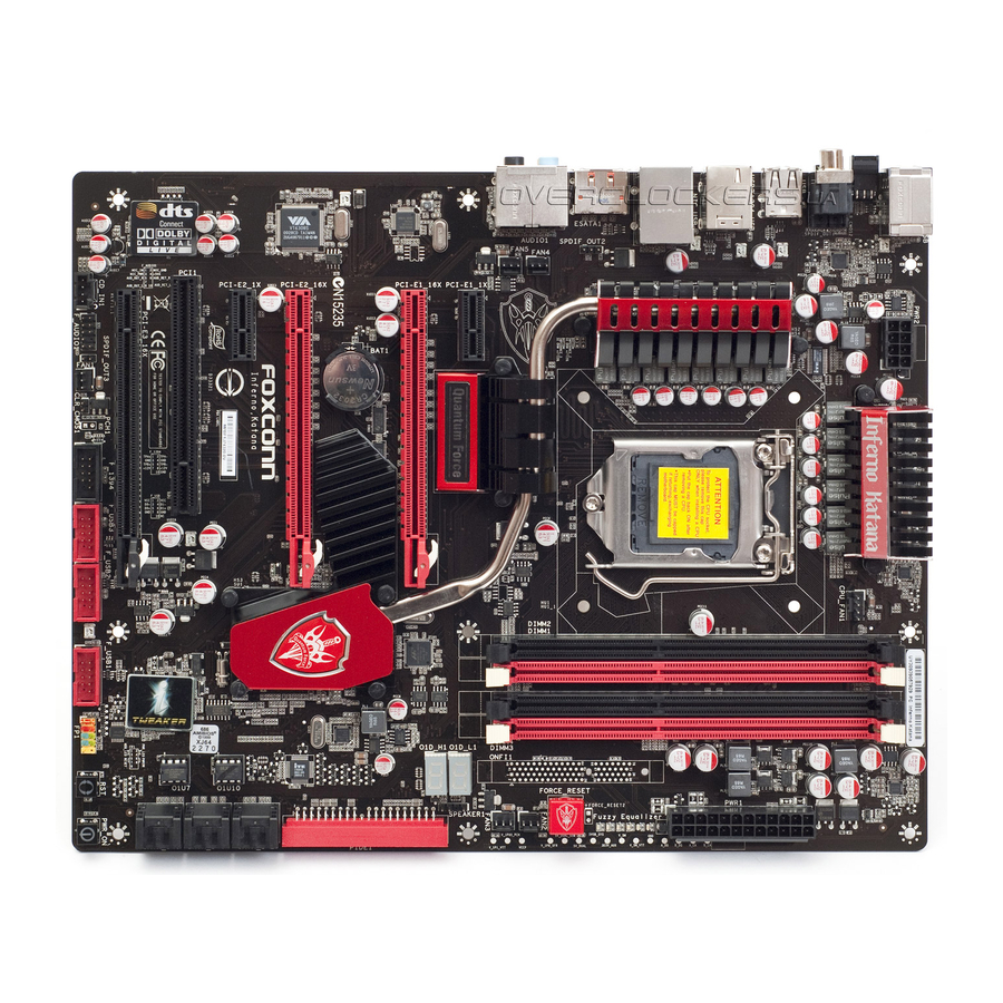
Page 11: Layout
7. PCI Slot 22. FAN3 Header 8. CD_IN Connector 23. FAN2 Header 9. Front Audio Connector 24. Force_Reset Button (Only for Inferno Katana) 10. S/PDIF Out 3 Connector 25. Fuzzy Equalizer 11. FAN1 Header 26. 24-pin ATX Power Connector 12. Clear CMOS Jumper 27. -
Page 12: Back Panel Connectors
6. 1394a Port (only for Inferno Katana) This port is used to connect a 1394a device. 7. external SATA Ports (only for Inferno Katana) To connect external SATA device(s) to your system by expanding the internal SATA port(s) to the chassis back panel. External SATA device shall provide power by its own. - Page 13 8. RJ-45 lAN Port The Ethernet LAN port provides Internet connection at up to 10/100/1000Mb/s data rate. Left: Active Right: Link LAN Type Active Link Status Description Status Description No Link No Link 10Mb/s Connection 1000M Green Data Green 100Mb/s Connection Blinking Activity Orange...
- Page 14 This chapter introduces the hardware installation process, including the installation of the CPU, memory, power supply, slots, pin headers and the mounting of jumpers. Caution should be exercised during the installation of these modules. Please refer to the motherboard layout prior to any installation and read the contents in this chapter carefully.
-
Page 15: Install The Cpu And Cpu Cooler
2-1 Install the CPU and CPU Cooler Read the following guidelines before you begin to install the CPU: ■ Make sure that the motherboard supports the CPU. ■ Always turn off the computer and unplug the power cord from the power supply before installing the CPU to prevent hardware damage. - Page 16 Follow the steps to install the CPU onto the CPU socket : Before installing the CPU, make sure to turn off the computer and unplug the power cord from the power outlet to prevent damage to the CPU. 2. Lift the metal cover on the CPU 1.
-
Page 17: Install The Cpu Cooler
Install the CPU Cooler Follow the steps below to correctly install the CPU cooler on the motherboard. 1. Apply and spread an even thermal 2. Place the four bolts of the CPU grease on the surface of CPU. cooler to the holes of the motherboard, push them straight down from the top, and the bolts will be fastened on the motherboard. -
Page 18: Install The Memory
2-2 Install the Memory Read the following guidelines before you begin to install the memory: ■ Make sure that the motherboard supports the memory. It is recommended that memory of the same capacity, brand, speed, and chips be used. ■ Always turn off the computer and unplug the power cord from the power outlet before installing the memory to prevent hardware damage. -
Page 19: Installing A Memory
Installing a Memory ■ Before installing a memory module, make sure to turn off the computer and unplug the power cord from the power outlet to prevent damage to the memory module. Be sure to install DDR3 DIMMs on this motherboard. Notch If you take a look at front side of memory module, it has asymmetric pin counts on both sides separated by a notch in the middle, so it can only fit in one direction. -
Page 20: Install An Expansion Card
2-3 Install an expansion Card ■ Make sure the motherboard supports the expansion card. Carefully read the manual that came with your expansion card. ■ Always turn off the computer and unplug the power cord from the power outlet before installing an expansion card to prevent hardware damage. -
Page 21: Install Other Internal Connectors
2-4 Install other Internal Connectors Power Connectors This motherboard uses an ATX power supply. In order not to damage any device, make sure all the devices have been installed properly before applying the power supply. 24-pin ATX Power Connector: PWR2 PWR2 is the ATX power supply connector. - Page 22 Connect a 4-pin power plug We recommend you using an 8-pin ATX 12V power supply. If you are using a 4-pin power supply, you need to align the ATX power connector according to the picture on the right. USb Connectors: f_USb1/2/3 In addition to the eight USB ports on the rear panel, this product also provides three 10-pin USB head- ers on its motherboard.
- Page 23 front Panel Connector: fP1 This motherboard includes one connector for connecting the front panel switch and LED Indicators. HDD-LED PWR-LED Hard Disk leD Connector (HDD-leD) RESET-SW PWR-SW Connect to the chassis front panel IDE indicator LED. It EMPTY indicates the active status of the hard disks. This 2-pin connector is directional with +/- sign.
- Page 24 EMPTY PORT2_L SENSE2_RETURN F_AUDIO 1394a Connector: f_1394 (only for Inferno Katana) The 1394a expansion cable can be connected to either the front (provided that the front panel of your chassis is equipped with the appropriate interface) or real panel of the chassis.
-
Page 25: Jumpers
2-5 Jumpers For some features needed, users can change the jumper settings on this motherboard to modify them. This section explains how to use the various functions of this motherboard by changing the jumper settings. Users should read the following content carefully prior to modifying any jumper setting. Description of Jumpers 1. -
Page 26: Onboard Button
CMOS. RESET POWER_ON CLS_CMOS force Reset button: foRCe_ReSeT (only for Inferno Katana) Simply rebooting after applying new OC settings can cause the system to fail because the hardware has not been reset properly. But with one press on the Force... -
Page 27: Onboard Led
2-8 onboard leD Core Nerve (Only for Inferno Katana): There are ten LEDs under the “Quantum Force” light. Their flashing frequency is following the power loading. The power loading is heavier, the leds flash faster. User can check the loading in time through this light. - Page 28 5.8. On power sequence, when Vdimm is ready. 5.9. On power sequence, but 1.05V PCH cannot ready. 5.A. On power sequence, when 1.05V PCH is ready. 5.B. On power sequence, but 1.1V VTT cannot ready. 5.D. On power sequence, when 1.1V VTT is ready. 5.F.
- Page 29 Both key sequence and OEM specific method is checked to determine if BIOS recovery is forced. If BIOS recovery is necessary, control flows to checkpoint E0. See Bootblock Recovery Code Checkpoints section of document for more information. Restore CPUID value back into register. The Bootblock-Runtime interface module is moved to system memory and control is given to it.
- Page 30 Make flash write enabled through chipset and OEM specific method. Detect proper flash part. Verify that the found flash part size equals the recovery file size. The recovery file size does not equal the found flash part size. Erase the flash part. Program the flash part.
- Page 31 Testing and initialization of different Input Devices. Also, update the Kernel Variables. Traps the INT09h vector, so that the POST INT09h handler gets control for IRQ1. Uncompress all available language, BIOS logo, and Silent logo modules. Early POST initialization of chipset registers. Relocate System Management Interrupt vector for all CPU in the system.
- Page 32 Execute BIOS setup if needed / requested. Check boot password if installed. Late POST initialization of chipset registers. Build ACPI tables (if ACPI is supported) Program the peripheral parameters. Enable/Disable NMI as selected Initialization of system management interrupt by invoking all handlers. Please note this checkpoint comes right after checkpoint 20h Clean-up work needed before booting to OS.
- Page 33 This chapter tells how to change system settings through the BIOS Setup menus. Detailed descriptions of the BIOS parameters are also provided. You have to run the Setup Program when the following cases occur : 1. An error message appears on the screen during the system Power On Self Test (POST) process.
-
Page 34: Enter Bios Setup
enter bIoS Setup The BIOS is the communication bridge between hardware and software, correctly setting up the BIOS parameters is critical to maintain optimal system performance. Power on the computer, when the message "Press Tab to show POST screen, Del to enter SETUP" appears at the bottom of the screen, you can press <DEL>... - Page 35 ► Power Management Setup All the items related with Green function features can be setup through this menu. ► PC Health Status This setup enables you to read/change fan speeds, and displays temperatures and voltages of your CPU/System. ► Quantum BIOS Some special proprietary features (such as overclocking) can be set up through this menu.
-
Page 36: System Information
System Information This sub-menu is used to set up the standard BIOS features, such as the date, time, memory and so on. Use the arrow up/down keys to select an item, then use the <+> or <-> keys to change the setting. - Page 37 System Memory ► System Memory Size This item displays the current memory size. The size is depending on how many memory mod- ules were installed in your system before powering on. ► OnBoard LAN MAC Address This item shows the onboard LAN MAC address.
-
Page 38: Advanced Bios Features
Advanced BIOS Features CMOS Setup Utility - Copyright (C) 1985-2009, American Megatrends, Inc. Advanced BIOS Features Advanced Settings Help Item Press Enter ► IDE configuration Press Enter Configure the IDE ► AHCI Configuration Press Enter device(s). ► MPS Configuration Press Enter ↑↓←→:Move Enter:Select +/-/:Value F10:Save ESC:Exit F1:General Help... - Page 39 AHCI provides more advanced features including SATA features, but some SATA drives may not support AHCI, unless they are labeled with AHCI support in its specification. If your motherboard supporting AHCI, and you have a SATA device, which also supports AHCI, then you can select IDE option to have fair performance (only PATA, SATA level), or you can select AHCI to get its best performance.
-
Page 40: Ahci Configuration
AHCI Configuration CMOS Setup Utility - Copyright (C) 1985-2009, American Megatrends, Inc. AHCI Configuration AHCI Settings Help Item AHCI BIOS Support Enables for supporting Enabled ► AHCI Port0 Not Detected ► AHCI Port1 Not Detected ► AHCI Port2 Not Detected ►... -
Page 41: Mps Configuration
MPS Configuration CMOS Setup Utility - Copyright (C) 1985-2009, American Megatrends, Inc. MPS Configuration MPS Configuration Help Item MPS Revision Select MPS Revision. ↑↓←→:Move Enter:Select +/-/:Value F10:Save ESC:Exit F1:General Help F9:Optimized Defaults ► MPS Revision This feature is only applicable to multiprocessor motherboards as it specifies the version of the MPS that the motherboard will use. -
Page 42: Advanced Chipset Features
Advanced Chipset Features CMOS Setup Utility - Copyright (C) 1985-2009, American Megatrends, Inc. Advanced Chipset Features Advanced Chipset Settings Help Item ► North Bridge Configuration Press Enter Configure North Bridge Press Enter ► South Bridge Configuration Press Enter features. ► OnBoard Device Configuration Press Enter ►... -
Page 43: South Bridge Configuration
South Bridge Configuration CMOS Setup Utility - Copyright (C) 1985-2009, American Megatrends, Inc. South Bridge Configuration South Bridge Chipset Configuration Help Item Options SMBUS Controller Enabled Enabled Debug Code Control Enabled SLP_S4# Min. Assertion Width 4 to 5 seconds Disabled PCIE Ports Configuration PCIE Port 0 Auto... -
Page 44: Onboard Device Configuration
OnBoard Device Configuration CMOS Setup Utility - Copyright (C) 1985-2009, American Megatrends, Inc. OnBoard Device Configuration OnBoard Device Configuration Help Item Options HDA Controller Enabled Enabled VIA 6308S 1394 Device Enabled Realtek 8111D LAN Device Enabled Enabled Realtek 8111D LAN BootROM Disabled Disabled Marvell 6121 PATA and eSATA eSATA + IDE ↑↓←→:Move Enter:Select... -
Page 45: Usb Configuration
USB Configuration CMOS Setup Utility - Copyright (C) 1985-2009, American Megatrends, Inc. USB Configuration USB Configuration Help Item Options Module Version - 2.24.3-13.4 USB Devices Enabled : Disabled None 2 USB Ports 4 USB Ports USB Functions 14 USB Ports 14 USB Ports 6 USB Ports Legacy USB Support... -
Page 46: Boot Configuration Features
Boot Configuration Features CMOS Setup Utility - Copyright (C) 1985-2009, American Megatrends, Inc. Boot Configuration Features Boot Settings Help Item ► Boot Settings Configuration Configure Settings [Press Enter] during System Boot. ► Boot Device Priority [Press Enter] ► Network Drives [Press Enter] ↑↓←→:Move Enter:Select +/-/:Value F10:Save ESC:Exit... -
Page 47: Quick Boot
Boot Settings Configuration CMOS Setup Utility - Copyright (C) 1985-2009, American Megatrends, Inc. Boot Settings Configuration Boot Settings Configuration Help Item Quick Boot Enabled Allows BIOS to Skip Enabled Quiet Boot Enabled certain tests while Bootup Num-Lock booting. This will Wait For ‘F1’... -
Page 48: Power Management Setup
Power Management Setup CMOS Setup Utility - Copyright (C) 1985-2009, American Megatrends, Inc. Power Management Setup Power Management Setup Help Item Suspend mode Auto Select the ACPI Auto Repost Video on S3 Resume state used for ACPI Version Features ACPI v1.0 System Suspend. - Page 49 computer before it entering STR will be saved in memory, and the computer can quickly return to previous state when the STR function wakes. When you select “Auto”, it means OS will automatically take care and assign which mode is the most suitable now.
-
Page 50: Pc Health Status
PC Health Status CMOS Setup Utility - Copyright (C) 1985-2009, American Megatrends, Inc. PC Health Status PC Health Status Help Item CPU Fan Ctrl Type Smart Fan Type Fan Ctrl Type: Smart Fan Type SYS Fan1 Ctrl Type Smart Fan Type Smart Fan Type Memory Fan2 Ctrl Type Smart Fan Type... -
Page 51: Quantum Bios
Quantum BIOS CMOS Setup Utility - Copyright (C) 1985-2009, American Megatrends, Inc. Quantum BIOS ► CPU Configuration Press Enter Help Item Press Enter ► Memory Timing Config Press Enter ► ALL Voltage Control Press Enter Configure CPU. ► OC Gear Press Enter *******Clockspeed Control Center******* CPU Bclock (FSB) -
Page 52: Cpu Configuration
CPU Configuration CMOS Setup Utility - Copyright (C) 1985-2009, American Megatrends, Inc. CPU Configuration CPU Core Current Speed : 2.93GHz Help Item Cache L1 : 128 KB Cache L2 : 1024 KB For UP platforms, Cache L3 : 8192 KB leave it enabled. - Page 53 Different processors support different numbers of C-states in which various parts of the CPU are turned off. This item is used to enable or disable C-State. ► C State package limit setting The selected option will be entered into C State package limit register. The default value is: [Auto]. ►...
- Page 54 Memory Timing Config CMOS Setup Utility - Copyright (C) 1985-2009, American Megatrends, Inc. Memory Timing Config PCI MMIO ALLocation: 4GB To 3328MB Help Item Memory Remap Feature Enabled Fast MRC Disabled Enabled: ALLow Configure DRAM Timing by SPD Auto remapping of DRAM Command Rate Auto over lapped PCI memory...
- Page 55 ALL Voltage Control CMOS Setup Utility - Copyright (C) 1985-2009, American Megatrends, Inc. ALL Voltage Control ******* CPU Voltages ******* Help Item CPU VCore Mode Dynamic Mode CPU Target Core Voltage Default Options CPU VTT (UnCore) Voltage 1.10V CPU VCore PWM VDroop Enabled Dynamic mode CPU Fuzzy Equalizer Control...
- Page 56 C-Addr (Command-address) reference voltage is reference DRAM voltage, the actual refer- ence voltage will be DRAM voltage multiply this item value. The default value is: [0.80V]. ► DIMM3,4 Vref C-Addr CA (Command-address) and DQ (Data line) reference voltage is reference DRAM voltage, the actual reference voltage will be DRAM voltage multiply this item value.
- Page 57 Press Enter or 6 or 7 or 8 to Clear Backup Slot Press Enter store your over clock setting. If you store ******* Foxconn Features ******* your setting to Over Clock Recovery Disabled current storage slot successfully, then the storage slot will turn to Green color.
-
Page 58: Bios Security Features
bIoS Security features CMOS Setup Utility - Copyright (C) 1985-2009, American Megatrends, Inc. BIOS Security Features Security Settings Help Item Supervisor Password :Not Installed Install or Change the User Password :Not Installed password. Press Enter Change Supervisor Password Press Enter Change User Password Press Enter Boot Sector Virus Protection... -
Page 59: Load Optimal Defaults
load optimal Defaults Optimal defaults are the best settings of this motherboard. Always load the Optimal defaults after updating the BIOS or after clearing the CMOS Load Optimal Defaults? values. Select this option and press Enter, it will pop out a dialogue box to let [OK] [OK] [Cancel]... - Page 60 The utility CD that came with the motherboard contains useful software and several utility drivers that enhance the motherboard features. This chapter includes the following information: ■ Utility CD Introduction ■ Aegis Panel ■ FOX LiveUpdate ■ FOX LOGO ■ FOX DMI Note : Because each module is independent, so the section number will be reorganized and unique to each...
-
Page 61: Utility Cd Introduction
Utility CD introduction This motherboard comes with one Utility CD. To begin with, simply insert the CD into your CD drive. The CD will automatically run and display the main menu on the screen. 1. Driver Select "Driver", then use these options to install all the necessary drivers for your motherboard. You must click "Intel Chipset Driver"... - Page 62 Use these options to install additional software programs. AeGIS PANel Foxconn new utility software for monitoring system information. See “AEGIS PANEL” for details. FOX LiveUpdate The Fox LiveUpdate allows you to backup or update the system BIOS, drivers and utilities in Windows environment.
- Page 63 Reader that is used for viewing and printing the PDF document. ® ® Norton Internet Security Installs Norton Internet Security to protect your PC from being affected by viruses. ® 3. foxconn WebSite Click it to visit Foxconn’s website. 4. browse CD Click it to browse the CD content.
-
Page 64: Aegis Panel
AeGIS PANel Aegis Panel, is a Windows innovation tool which provides settings of OC gear, overclocking, fan control and alarm function. It also displays system monitoring information such as fan speed, temperature, voltage and CPU clock etc.. The powerful features are: HW Monitor(Hardware Monitor Information) Overclocking OC Gear (Optional) -
Page 65: Hw Monitor
2. HW Monitor Click on "HW Monitor" icon , its panel appears. By moving the mouse on the voltage icon, it will display voltage information. Move the mouse on fan or temperature icon will show relative information accordingly. Voltage icon Fan icon Temperature icon 2.1 HW Monitor - Voltage... - Page 66 2.2 HW Monitor - fan Move the mouse on the fan icon , its menu appears. Click on the fan icon to get into the fan setting menu. It allows you to set the low/high limits of the CPU, NB and System fan speeds, and to enable the alert function.
-
Page 67: Overclocking
3. Overclocking Click "Overclocking" icon to enter the overclok setting menu. It allows you to adjust CPU clock, and to change the voltages of CPU, chipset and memory. After you set the values, click [Apply] button to apply it. Click these buttons to adjust the CPU clock Click these buttons to adjust the CPU voltages... -
Page 68: Fox Liveupdate
FOX LiveUpdate FOX LiveUpdate is a useful utility to backup and update your system BIOS, drivers and utilities by local or online. Supporting Operating Systems : ■ Windows XP (32-bit and 64-bit) ■ Windows Vista (32-bit and 64-bit) Using FOX LiveUpdate : 1. - Page 69 1-2 local Update - backup This page can backup your system BIOS. You can click “Backup”, and key in a file name, then click “Save” to finish the backup operation. The extension of this backup file is ".BIN" for Award BIOS and ".ROM"...
-
Page 70: Online Update
2. online Update 2-1 online Update - Update bIoS This page lets you update your system BIOS from Internet. Click “start”, it will search the new BIOS from Internet. Then follow the wizard to finish the update operation. Click here Current information Search new BIOS from Internet... - Page 71 Select the driver to update Browse detailed information Install the selected driver Close the window 2-3 online Update - Update Utility This page lets you update utilities from Internet. Click “start”, it will search the new utilities from Internet. Then follow the wizard to finish the update operation. Click here Current information Search new utilities...
- Page 72 2-4 online Update - Update All This page lets you update your system drivers from Internet. Click “start”, it will search all new BIOS/drivers/utilities from Internet. Then follow the wizard to finish the update operation. Click here Current information Search all new BIOS/ drivers/utilities from Internet Browse detailed...
-
Page 73: Configure
3. Configure 3-1 Configure - option This page lets you set auto search options. After you enable the auto search function, FOX LiveUpdate will start its searching from Internet and if any qualified item found, it will pop out a message on the task bar to inform you to do the next step. - Page 74 When you enable "Auto Search FOX LiveUpdate", if your FOX LiveUpdate version is older, it will auto search from internet and prompt you to install the new version. Prompt you to install the new FOX LiveUpdate 3-2 Configure - System This page lets you set the backup BIOS location and change different skin of the FOX LiveUpdate utility.
-
Page 75: About & Help
3-3 Configure - Advance This page lets you select to flash BIOS / Boot Block and clear CMOS. If you choose Flash Boot Block, it means BIOS is not protective, and you must make sure the flash process is continuous and without any interruption. -
Page 76: Fox Logo
Windows XP (32-bit and 64-bit) ■ Windows Vista (32-bit and 64-bit) Using FOX LOGO: Main Page Here use Inferno Katana as the example. The marketing name on Inferno Katana GTI's boot screen will show "Inferno Katana GTI". Main screen Exit Backup... -
Page 77: Fox Dmi
foX DMI FOX DMI is a full Desktop Management Interface viewer, and it provides three DMI data formats: Report, Data Fields and Memory Dump. With DMI information, system maker can easily analyze and troubleshoot your motherboard if there is any problem occurred. Supporting Operating Systems : ■... - Page 78 This chapter will cover two topics : ■ Installing a new Windows XP (Vista) in a brand new RAID system. ■ Existing Windows XP (Vista) system with new RAID built as data storage. It includes the following information : ■ RAID Configuration Introduction ■...
-
Page 79: Data Storage
Installing a new Windows XP (Vista) in a brand new RAID system. 1. Follow 5-1 to create a RAID driver diskette. (Windows Vista has in-box driver by its own and can skip this step). 2. Follow 5-2 to set BIOS setting "SATA Mode" to RAID or AHCI. 3. -
Page 80: Raid Configuration Introduction
RAID Configuration Introduction RAID (Redundant Array of Independent Disks) is a method for computer data storage schemes that divide and/or replicate data among multiple hard drives. RAID can be designed to provide increased data reliability (fault tolerance) or increased I/O ®... - Page 81 RAID 0 (Stripe) RAID 0 reads and writes sectors of data interleaved among multiple drives. If any disk member fails, it affects the entire array. The disk array data capacity is equal to the number of drive members times the capacity of the smallest member. The striping block size can be set from 4KB to 128KB.
-
Page 82: Intel® Matrix Storage Manager
Intel Matrix Storage Manager ® The Intel Matrix Storage Manager technology supports RAID 0 ,RAID 1, RAID 5, and ® RAID 10 (0+1) functions. It allows you to get high performance with fault tolerance, big capacity, or data safety provided by different RAID functions. In this section, we will use four SATA hard disks as an example to guide you how to configure your RAID system. -
Page 83: Create A Raid Driver Diskette
5-1 Create a RAID driver diskette If you want to install a brand new Windows XP on a AHCI or RAID system, you need to configure the SATA Mode in BIOS to either AHCI or RAID first. You also need to create a RAID driver diskette for use in installing your Windows XP system. - Page 84 6. You can input a volume label for this diskette, click on "Start" to format. 7.Click on "OK" to go through this warning message. 8. Format finished. Click "OK" to continue copying of RAID driver into this diskette. 9. Check if the diskette contains the driver files. Later, when in the process of installing Windows XP in your RAID system, it will ask you to use this floppy diskette to provide driver for additional specific devices, for example, a RAID device.
-
Page 85: Bios Configuration
5-2 BIOS Configuration 1. Enter the BIOS setup by pressing <DEL> key during the POST(Power On Self Test). 2. Select the “Advanced BIOS Features” from the “Main menu”, then select the “IDE Configuration” item and press <Enter> to go to the configuration items. 3. -
Page 86: Create Raid Volume
Create RAID Volume Create RAID 0 (1st Volume) 1. Select “1. Create RAID Volume” from the menu and press <Enter>. The menu appears : Intel(R) Matrix Storage Manager option ROM v8.9.0.1023 PCH-D wRAID5 Intel(R) Matrix Storage Manager option ROM v5.0.0.1011 ICH9R wRAID5 Copyright(C) 2003-09 Intel Corporation. -
Page 87: Creating Raid 1
4. It then goes to “Disks” item. Press <Enter> to display the hard disks list for this RAID0 system. Intel(R) Matrix Storage Manager option ROM v8.9.0.1023 PCH-D wRAID5 Intel(R) Matrix Storage Manager option ROM v5.0.0.1011 ICH9R wRAID5 Copyright(C) 2003-09 Intel Corporation. All Rights Reserved. Copyright(C) 2003-04 Intel Corporation All Rights Reserved. - Page 88 6. It is now entering “Strip Size” menu. Use Up or Down arrow key to select the desired strip size. The available values range from 4KB to 128KB. The strip value should be selected based on different applications. Some suggested choices are : 16K - Best for sequential transfer.
- Page 89 8. In “Create Volume” item, press <Enter>. Intel(R) Matrix Storage Manager option ROM v5.0.0.1011 ICH9R wRAID5 Intel(R) Matrix Storage Manager option ROM v8.9.0.1023 PCH-D wRAID5 Copyright(C) 2003-04 Intel Corporation All Rights Reserved. Copyright(C) 2003-09 Intel Corporation. All Rights Reserved. CREATE VOLUME MENU Name: TryRAID0 RAID Level:...
- Page 90 Create RAID0 (2nd Volume) 1. Select “1. Create RAID Volume” from the menu and press <Enter>. The menu appears : Intel(R) Matrix Storage Manager option ROM v8.9.0.1023 PCH-D wRAID5 Intel(R) Matrix Storage Manager option ROM v5.0.0.1011 ICH9R wRAID5 Copyright(C) 2003-09 Intel Corporation. All Rights Reserved. Copyright(C) 2003-04 Intel Corporation All Rights Reserved.
- Page 91 4. It then goes to “Disks” item. Press <Enter> to display the hard disks list for this RAID0 second volume system. Intel(R) Matrix Storage Manager option ROM v8.9.0.1023 PCH-D wRAID5 Intel(R) Matrix Storage Manager option ROM v5.0.0.1011 ICH9R wRAID5 Copyright(C) 2003-09 Intel Corporation. All Rights Reserved. Copyright(C) 2003-04 Intel Corporation All Rights Reserved.
- Page 92 6. It goes to “Strip Size” menu directly. Capacity automatically displays 512.2GB, and at this time, you can not input any value in capacity as there is no additional volume available. The available values of Strip Size range from 4KB to 128KB. The strip value should be selected based on different applications.
- Page 93 A message will appear : Are you sure you want to create this volume ? (Y/N) : Press <Y> to create the volume and return to the main menu. Two RAID0 volumes were configured. Intel(R) Matrix Storage Manager option ROM v5.0.0.1011 ICH9R wRAID5 Intel(R) Matrix Storage Manager option ROM v8.9.0.1023 PCH-D wRAID5 Copyright(C) 2003-04 Intel Corporation All Rights Reserved.
-
Page 94: Create Raid
Create RAID 1 1. Select “1.Create RAID Volume” from the main menu and press <Enter>. 2. In "Name" item, you can input a device name for the RAID1 system and press <Enter> to apply it. Here, we name it as TryRAID1 to replace the default Volume0. Intel(R) Matrix Storage Manager option ROM v5.0.0.1011 ICH9R wRAID5 Intel(R) Matrix Storage Manager option ROM v8.9.0.1023 PCH-D wRAID5 Copyright(C) 2003-04 Intel Corporation All Rights Reserved. - Page 95 4. It then goes to “Disks” item. Press <Enter> to dispaly the hard disks list for this RAID1 system. Intel(R) Matrix Storage Manager option ROM v8.9.0.1023 PCH-D wRAID5 Intel(R) Matrix Storage Manager option ROM v5.0.0.1011 ICH9R wRAID5 Copyright(C) 2003-09 Intel Corporation. All Rights Reserved. Copyright(C) 2003-04 Intel Corporation All Rights Reserved.
- Page 96 6. It will skip “Strip Size” menu for RAID1. Intel(R) Matrix Storage Manager option ROM v5.0.0.1011 ICH9R wRAID5 Intel(R) Matrix Storage Manager option ROM v8.9.0.1023 PCH-D wRAID5 Copyright(C) 2003-04 Intel Corporation All Rights Reserved. Copyright(C) 2003-09 Intel Corporation. All Rights Reserved. CREATE VOLUME MENU Name: TryRAID0...
- Page 97 Create RAID 10 (0+1) 1. Select “1.Create RAID Volume” from the main menu and press <Enter>. 2. In "Name" item, you can input a device name for the RAID10 system and press <Enter> to apply it. Here, we name it as TryRAID10 to replace the default Volume0. Intel(R) Matrix Storage Manager option ROM v8.9.0.1023 PCH-D wRAID5 Intel(R) Matrix Storage Manager option ROM v5.0.0.1011 ICH9R wRAID5 Copyright(C) 2003-09 Intel Corporation.
- Page 98 4. After exiting from "RAID Level", it goes directly to "Stripe Size" item. Because all four disks are selected for RAID10, so there is no need to go to Disks option. 5. Use Up or Down arrow key to select the desired strip size when entering “Strip Size”...
- Page 99 Create RAID5 (Parity) 1. Select “1.Create RAID Volume” from the main menu and press <Enter>. 2. In "Name" item, you can input a device name for the RAID5 system and press <Enter> to apply it. Here, we name it as TryRAID5 to replace the default Volume0. Intel(R) Matrix Storage Manager option ROM v8.9.0.1023 PCH-D wRAID5 Intel(R) Matrix Storage Manager option ROM v5.0.0.1011 ICH9R wRAID5 Copyright(C) 2003-09 Intel Corporation.
- Page 100 4. It then goes to “Disks” item. Press <Enter> to display the hard disks list for this RAID5 system. Intel(R) Matrix Storage Manager option ROM v5.0.0.1011 ICH9R wRAID5 Intel(R) Matrix Storage Manager option ROM v8.9.0.1023 PCH-D wRAID5 Copyright(C) 2003-04 Intel Corporation All Rights Reserved. Copyright(C) 2003-09 Intel Corporation.
- Page 101 6. Use Up or Down arrow key to select the desired strip size when entering “Strip Size” menu. The default value is 64K. Press <Enter>. Intel(R) Matrix Storage Manager option ROM v5.0.0.1011 ICH9R wRAID5 Intel(R) Matrix Storage Manager option ROM v8.9.0.1023 PCH-D wRAID5 Copyright(C) 2003-04 Intel Corporation All Rights Reserved.
- Page 102 Create Recovery 1. Select “1.Create RAID Volume” from the main menu and press <Enter>. 2. In "Name" item, you can input a device name for the Recovery system and press <Enter> to apply it. Here, we name it as TryRecovery to replace the default Volume0. Intel(R) Matrix Storage Manager option ROM v8.9.0.1023 PCH-D wRAID5 Intel(R) Matrix Storage Manager option ROM v5.0.0.1011 ICH9R wRAID5 Copyright(C) 2003-09 Intel Corporation.
- Page 103 4. It then goes to “Disks” item. Press <Enter> to display the hard disks list for this Recovery system. Intel(R) Matrix Storage Manager option ROM v5.0.0.1011 ICH9R wRAID5 Intel(R) Matrix Storage Manager option ROM v8.9.0.1023 PCH-D wRAID5 Copyright(C) 2003-04 Intel Corporation All Rights Reserved. Copyright(C) 2003-09 Intel Corporation.
- Page 104 6. It will skip “Strip size” and “Capacity” items. The default “Capacity” value is the smaller hard disk size, that is 74.5GB. In “Sync” item, we suggest you select the “Continuous” value and press <Enter>. Intel(R) Matrix Storage Manager option ROM v5.0.0.1011 ICH9R wRAID5 Intel(R) Matrix Storage Manager option ROM v8.9.0.1023 PCH-D wRAID5 Copyright(C) 2003-04 Intel Corporation All Rights Reserved.
-
Page 105: Delete Raid Volume
Delete RAID Volume 1. Take TryRAID5 for example. Select “2. Delete RAID Volume” in main menu and press <Enter>. Intel(R) Matrix Storage Manager option ROM v8.9.0.1023 PCH-D wRAID5 Intel(R) Matrix Storage Manager option ROM v5.0.0.1011 ICH9R wRAID5 Copyright(C) 2003-09 Intel Corporation. All Rights Reserved. Copyright(C) 2003-04 Intel Corporation All Rights Reserved. - Page 106 3. After <DEL> key is pressed, the screen appears as below: Press <Y> key to confirm the volume deletion. Intel(R) Matrix Storage Manager option ROM v5.0.0.1011 ICH9R wRAID5 Intel(R) Matrix Storage Manager option ROM v8.9.0.1023 PCH-D wRAID5 Copyright(C) 2003-04 Intel Corporation All Rights Reserved. Copyright(C) 2003-09 Intel Corporation.
-
Page 107: Reset Disks To Non-Raid
Reset Disks to Non-RAID Reset RAID volume allows you to replace a failed disk with a new one, and the operating system will rebuild the data later. For RAID0, reset a hard disk would totally crash the system, but for RAID1, RAID10 and RAID5, they all can be rebuilt. When rebuild is needed, you must first install a new hard disk in your system before getting into Intel Matrix Storage Manager utility, because the utility will ask you which... - Page 108 3. Select Maxtor hard disk as the one to be reset. Press <Enter>. A double confirmation message pops out, press <Y> to confirm. Intel(R) Matrix Storage Manager option ROM v5.0.0.1011 ICH9R wRAID5 Intel(R) Matrix Storage Manager option ROM v8.9.0.1023 PCH-D wRAID5 Copyright(C) 2003-04 Intel Corporation All Rights Reserved.
- Page 109 example 2. Reset a RAID5 system 1. A TryRAID5 volume was built with three hard disks, we want to reset one of them. Select “3. Reset Disks to Non-RAID” in main menu and press <Enter>. Intel(R) Matrix Storage Manager option ROM v5.0.0.1011 ICH9R wRAID5 Intel(R) Matrix Storage Manager option ROM v8.9.0.1023 PCH-D wRAID5 Copyright(C) 2003-04 Intel Corporation All Rights Reserved.
- Page 110 4. A "DeGRADeD VolUMe DeTeCTeD" screen pops out asking you to select a new hard disk for rebuilding. Here, we select WDC 232.9GB. Press <Enter> to select it. Intel(R) Matrix Storage Manager option ROM v5.0.0.1011 ICH9R wRAID5 Intel(R) Matrix Storage Manager option ROM v8.9.0.1023 PCH-D wRAID5 Copyright(C) 2003-04 Intel Corporation All Rights Reserved.
-
Page 111: Exit Raid Bios
exit RAID bIoS 1. Take TryRAID5 as an example, select “5. exit” in main menu and press <Enter>. The screen displays : Intel(R) Matrix Storage Manager option ROM v5.0.0.1011 ICH9R wRAID5 Intel(R) Matrix Storage Manager option ROM v8.9.0.1023 PCH-D wRAID5 Copyright(C) 2003-04 Intel Corporation All Rights Reserved. -
Page 112: Install A New Windows Xp
5-4 Install a New Windows XP hen you set the SATA Mode in BIOS to either AHCI or RAID, you need to follow these steps to install your Windows XP system. 1. Press <DEL> to enter BIOS Setup during POST. 2. - Page 113 5. After some files are copied to your system, the following picture appears, press <S> to continue the specific driver installation. Windows Setup Setup could not determine the type of one or more mass storage devices installed in your system, or you have chosen to manually specify an adapter. Currently, Setup will load support for the following mass storage device(s): <none>...
- Page 114 7. Depending on South Bridge chip of your system, select appropriate driver for it. Here, we choose Intel ICH8R/ICH9R/ICH10R/D0/PCH SATA RAID Controller. ® Press <Enter> to select it. Windows Setup You have chosen to configure a SCSI Adapter for use with Windows, using a device support disk provided by an adapter manufacturer.
- Page 115 9. Windows will display the partition of your system, you have to create partitions as many as you wish, assign them C:, D: or E: drive names. After partitions were done, you can press <Enter> to continue. It will ask you to format your hard disk, then copy files...etc., until the whole Windows is setup.
-
Page 116: Existing Windows Xp With Raid Built As Data Storage
5-5 Existing Windows XP with RAID built as data storage When you already have a Windows XP system running at a traditional IDE hard disk, and you want to keep it unchanged, but you also want to expand the system with some SATA hard disks, to come out a new RAID system for data storage. - Page 117 2. Copy section 5-2, BIOS Configuration. Shut down the computer, connect SATA hard disks to SATA ports, power on computer again. Press <Del> key, get into BIOS, set "SATA Mode" to [RAID], press <F10> to save and exit BIOS. PC will reboot. CMOS Setup Utility - Copyright (C) 1985-2009, American Megatrends, Inc.
- Page 118 ® 5. Use Explorer to get into the Intel driver directory which was previously copied to the desktop. ® 6. Click on Setup.exe to install Intel Matrix Storage Manager.
- Page 119 7. Install complete. 8. In Windows Explorer, right click on My Computer, click on Manage, then click on Disk Management to format these new RAID disks. Follow the Wizard to finish the job.
-
Page 120: Tm Technology
Catalyst Control Center : ■ CrossFireX Ready motherboard, such as Foxconn’s Inferno Katana/ Inferno Katana GTI. ■ 2 or 3 CrossFireX graphics cards For the detailed CrossFireX Graphic Card support list on this motherboard, please visit the website: http://www.foxconnchannel.com... - Page 121 6. Power on your computer and get into OS (Windows XP 32-bit with SP2 or ® Windows XP Professional 64-bit Edition). ® 7. Install Microsoft’s .NET Framework Version 1.1. Without it, the ATI Catalyst Control Center can not launch properly. 8.
-
Page 122: Appendix - Nvidia ® Sli™ Technology
NVIDIA ® Technology 1. Introduction NVIDIA ® (Scalable Link Interface) technology takes advantage of the increased bandwidth of the PCI Express bus architecture, and features intelligent hardware and software solutions to deliver earth-shattering PC performance in a multi NVIDIA ® GPU solution. - Page 123 3. Connect power extension cable from the power supply to the graphics card power connector separately. 4. Connect a monitor DVI-I cable to the graphics card. 2-2 Installing the graphics cards drivers 1. Power on your computer and boot into Operating System. 2.
- Page 124 Click "Advanced Settings" from the dialog box. Select the NVIDIA GeForce tab, then click "Start the NVIDIA Control Panel". 2. When using two graphics cards: Select “Set SLI Configuration”, then click "Enable 2-way NVIDIA SLI", when done, click Apply to enable it. Select the “3D Setting”...