Table of Contents
Advertisement
f
Save This Manual
For Future Reference
,__AIRS
owners
manual
MODEL NO.
113.221620
Serial
Number
Model and serial numLxzrs
may be found
at the
left-hand
side of the base.
You should
record both
model
and serial number
in a safe place
for future
Use,
FOR YOUR
SAFETY
READ ALL
INSTRUCTIONS
CAREFULLY
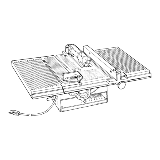
_'__AIRS/ CRRFTSMRN
8 INCH
DIRECT
DRIVE
TABLE SA W
• assembly
• operating
• repair
parts
J
Sears, Roebuck
and Co., Hoffman
Estates,
IL. 60179 U.S.A.
Part No. SP5311
Printed in U.S.A.
Advertisement
Table of Contents

Related Manuals for Craftsman 113.221620


Summary of Contents for Craftsman 113.221620
- Page 1 Save This Manual For Future Reference ,__AIRS owners manual MODEL NO. 113.221620 Serial Number Model and serial numLxzrs _'__AIRS/ CRRFTSMRN may be found at the left-hand side of the base. You should record both model and serial number 8 INCH DIRECT DRIVE in a safe place...
-
Page 2: Safety Instructions
FULL ONE YEAR WARRANTY ON CRAFTSMAN TABLE If within one year from the date of purchase, this Craftsman Table Saw fails due to a defect material or workmanship, Sears wil! repair it, free of charge. WARRANTY SERVICE IS AVAILABLE BY SIMPLY... - Page 3 for recommended accessories. The use of Noise levels vary widely. To avoid possible improper accessories may cause risk of injury hearing damage, wear plugs muffs to persons. when using saw for long periods of time. 2. Choose the right blade or cutting accessory Any power saw can throw foreign...
- Page 4 - Nevercut morethan one workpieceat a c. Wait for all moving parts to stop. time. d. Check blade, spreader and fence for proper -Never turn your table saw "ON" before alignment before starting, again. clearingeverythingexceptthe workpiece 8. To avoid throwback of small, cut off pieces: andrelated supportdevices off the table,...
-
Page 5: Cross Cut Type Cuts
additional instructions CROSS CUT TYPE CUTS While cutting avoid blade contact, always hold the miter gauge as shown in the BASIC SAW OPERA- Before starting TIONS - USING THE MITER GAUGE. - NEVER use the rip fence when crosscutting. - An auxiliary wood facing attached to the miter BEFORE LEAVING THE SAW... -
Page 6: Motor Specifications
MOTOR SPECIFICATIONS AND ELECTRICAL REQUIREMENTS The AC motor used in this saw is a non-reversible type, tool housing at one end and to the ground prong in the with the following specifications: attachment plug at the other end. Amperes ......This plug requires a mating 3-conductor grounded type Hertz ......... -
Page 7: Tools Needed
CONTENTS WARRANTY ......GETTING TO KNOW YOUR SAW .... On-Off Switch ......GENERAL SAFETY INSTRUCTIONS Elevation Handwheel ..... FOR POWER TOOLS ..... Tilt Handwheel ......ADDITIONAL SAFETY INSTRUCTIONS Miter Gauge ......Blade Guard ......FOR TABLE SAWS ....... Table Insert ......MOTOR SPECIFICATIONS AND ELECTRICAL Rip Fence... -
Page 8: List Of Loose Parts
Model 113.221620 Table Saw with Table Extensions shipped complete in one carton. Separate all parts from packing materials and check each with the illustration and the list of Loose Parts to make certain all items are accounted for, before discarding any packing material. - Page 9 ADJUSTING BLADE INSERT 1. Turn saw over. 2. Loosen Phillips screw in blade insert.., do not remove. 3. Remove blade insert by lifting slightly and pulling BLADE INSERT insert toward front of saw to disengage from hole slot. PHILLIPS HEAD SCREW 4.
- Page 10 CHECKING HEELING OR PARALLELISM OF SAW BLADE MITER GAUGE GROOVE MARK 'X' ON TOOTH While cutting, the material must move in a straight line PARALLEL to the SAW BLADE . . . therefore both the miter gauge GROOVE and the RIP FENCE must be PARALLEL to the SAW...
- Page 11 2.Folda pieceof cardboard or heavy paperoverthe bladeto protectyour hands. 3. Graspthe bladeandthecradlerodandmove the mechanism rightor leftasmallamount a sneeded to makethe square touchthesameamountfront and rear.Tightenonescrew. 4. Checkwithsquare todetermine if MARKED tooth touchessquarethe sameamountat front and rear. If it does-- alternately tightenotherthreescrews slowly.
- Page 12 ADJUSTING 90 DEGREE BEVEL STOP 1. On the stop bracket 10-32 head screws which set 90 ° stop position. If condition exists the two screws need to be turned clockwise to obtain 90 ° setting. If condition B exists srews should be turned counterclockwise.
- Page 13 CHECKING 45 DEGREE BEVEL STOP !. Turn elevation handwheel clockwise raise blade as high as it will go. 2. Turn bevel handwheel clockwise to tilt blade 45 ° ' 3. Lay head of combination square on the blade square as illustrated and place head against blade•...
-
Page 14: Aligning Table Extensions
3. Install left table extensionand install seven screwsusing5/32inch hexL wrench•Juststart screws. ALIGNING TABLE EXTENSIONS NOTE: The table extensions must be the same height as the table and level. NOTE: When aligning the table extensions, the 1/4-20 x 5/8 inch flat head hex socket screws may "bottom- out". -
Page 15: To Lower Outer Edge Of Extension
LOWER EXTENSION If extension is too high loosen four screws underside of the extension D, E, F, and G. See ,1 ,L,l,l,l,_,l,l,l,l,[,I,l,i,l,l,l,l,l,l,l,l,l,l,l,l,l,I,] illustration. --L_r Tighten screws B and C on of table extension to lower extension even with table front and rear. - Page 16 ALIGNING TABLE EXTENSIONS WITH FRONT OF TABLE 1. Place blade of combination square on front , ;I table and table extension. SHOULD ;iij 2. Extension should line up with table. J" MOVE OUTER EDGE EXTENSION BACK 1. Loosen screws C and F in right extension, illustration.
- Page 17 SQUARE SUPPORTs.. SPREADER TRUSS HEAD SPREADER BRACKET SCREW IN. LONG "-_--_ _._-_-----__ _// SPREADER CLAMP INSTALLING BLADE GUARD SOCKET HEAD _-°- _V/// 1. From among the loose parts, find the hardware SETSCREW WING shown. IN. LONG ""['_-_ "1_ HEX NUT LOCKWASHER EXT.
-
Page 18: Aligning Spreader
6. Laya pieceof flatstraightwoodanda square on sawtableandrotatethe SPREADER S UPPORT until the bracketis alignedwith square. 7. MAKESURE END OF SUPPORT, B RACKET ANDRODAREEVEN... usingan 1/8in, HexL wrench,TIGHTEN THESETSCREWS ONLY. ENDS OF SUPPORT BRACKET BE EVEN WITH OF ROD TIGHTEN SETSCREW ONLY !SPACE EQUAL... -
Page 19: Attaching Rip Fence
PIECE STRAIGHT WOOD 2. Installthe SPREADER CLAMP.Placespreader between spreaderclamp and bracket. Move TIGHTLY AGAINST HOLD WOOD forwarduntilallthreeareinline.TIGHTEN WING BLADE NUTS. 3. Lay a piece of straight flat wood againstthe sawblade. I nsertfoldedpaperbetween spreader andstrip of wood. ANTIKICKBACK PAWLS 4. MAKE SURETHE HEX NUTS UNDERNEATH ARELOOSE•... -
Page 20: Aligning Rip Fence
12-3/4 REAR OF SAW OPENING 4 HOLES .312 DIA. MOUNTING LEGS BENCH If you purchase Craftsman Steel Legs for your saw, assemble them according directions furnished with them. 10-7/8 11-7/8 If you mount the saw on any other... -
Page 21: Elevation H Andwheel
GETTING TO KNOW YOUR SAW 5 BLADE GUARD SPREADER TABLE INSERT 8 SAWBLADE\ % R,PFENCE MITER \ ..\\\\ MITER GUAGE EXTENSION LOCK 2 ELEVATION H ANDWHEEL POWER CORD ON-OFF SWITCH 1. ON-OFF SWITCH CAUTION: Before turning switch on, make sure blade guard is correctly... -
Page 22: Tilt Handwheel
2. ELEVATION HANDWHEEL... elevates or lowers D. Lift insert from front end, and pull toward front blade. Turn counterclockwise to elevate •.. of saw. clockwise to lower• NEVER OPERATE WITHOUT 3. TILT HANDWHEEL . . . tilts the blade for bevel PROPER INSERT IN PLACE. - Page 23 PULL LOOSEN/_ PUSH TIGHTEN 3. Turn elevation handwheel clockwise raise motor shaft as high as it will go. 4. Insert shaft wrench over flat portions of motor spacer and arbor wrench over arbor nut. 5. Hold shaft wrench loosen arbor with ARBOR arbor...
-
Page 24: Basic Saw Operation
BASIC SAW OPERATION USING MITER GAUGE by the back of the blade and thrown toward CROSSCUTTING, MITER CUTTING, BEVEL operator). Stand to either side of the blade. CUTTING, COMPOUND MITER CUTTING when RABBETING across of a narrow Keep your hands clear of the blade and out of... -
Page 25: Auxiliary Fence
3/8 PLYWOOD AUXILIARY FENCE PLYWOOD Make using a piece of 3/8 plywood. Fasten together with glue 1-1/8 woodscrews. NOTE: Since Push Block is used with Auxiliary Fence, the 4-3/4 in. dimensions must held identical on both the pieces. THIS FACE _"... -
Page 26: Repetitive Cutting
REPETITIVE CUTTING REPETITIVE CUTTING is cutting a quantity pieces the same length without having to mark each piece. NOTE: When making repetitive cuts from a long workpiece make sure it is supported. 1. NEVER FENCE AS A LENGTH STOP BECAUSE THE CUTOFF PIECE COULD... -
Page 27: Using The Rip Fence
WORKPIECE BEVEL CROSSCUTTING BEVEL CROSSCUTTING is the same as cross- cutting except that the wood is cut at an angle... other than 90 ° with the fiat side of the wood. Adjust the blade to the desired angle. Use the Miter Gauge in the groove to the RIGHT the blade. -
Page 28: Ripping
WORKPIECE RIPPING RIPPING is cutting a piece of wood with the grain, or lengthwise. This is done using the rip fence. Position the fence to the desired WIDTH OF RIP and TABLE lock in place. Before starting to rip, be sure A. - Page 29 When "WIDTH OF RIP" is2 in. to6 in. wide USE THE PUSH STICK to feed the work. i WIDTH When "WIDTH OF RIP" is NARROWER than 2 in., the push stick CANNOT be used because the guard will interfere AUXILIARY FENCE/WORK suPPORT and PUSH...
-
Page 30: Ploughing And Molding
BAFFLE Narrow stripsthickerthantheAuxiliaryFence/Work Supportmayenterthe guardandstrikethe baffle. CAREFULLY raiseguardonlyenoughto clearthe workpiece. U sePUSHBLOCK to completecut. RESAWING RESAWING is a "thru-sawing" cut made by ripping a piece of wood through its thickness. attempt to res'aw BOWED or WARPED material. NOTE: RESAW a piece of wood it will necessary... -
Page 31: Using Featherboards
RABBETING RABBETING is known as cutting out a section of the corner of a piece of material, across an end or along FIRST an edge. RABBET ISECOND To makea RABBET requirescutswhich do not go all the way through the material. Therefore the blade guard... -
Page 32: Maintenance
Frequently blow out any dust that may accumulate ,nside the saw cabinet and the motor. Freq_,ent!y clean your cutting tools with Craftsman and Pitch Remover. A coat of automobile-type v,._x applied to the table wlii help keep surface clean allow wor,.p=eces... -
Page 33: Lubrication
SAE No. 20 or No. 30 engine oil. 1. Elevation guide slot and pivot. 2. Elevation screw threads. 3. Bevel screw threads (First clean with Craftsman Gum & Pitch Remover.) 4. Bevel and elevation link pivot points. 5. Cradle pivot pin bearing points. - Page 34 Sears Recommends the Following Accessories ITEM CAT. Sears may recommend other accessories not listed in the manual. Saw Blades ..........See Catalog See your nearest Sears store for other accessories. Molding Head Set ........See Catalog Dado Insert ............9-22281 Do not use any accessory unless you have received and read complete instructions for use.
-
Page 35: Trouble Shooting
TROUBLE SHOOTING -- MOTOR NOTE: Motors used wood-working tools particulary susceptible accumulation sawdust and wood chips and should be blown out or "vaccummed" frequently to prevent interferences with normal motor ventilation. NOTE: The starting relay is a GRAVITY SENSITIVE TYPE. NEVER TURN THE POWER... - Page 36 "_-" _..--..--7 i_.- --__'_I _,o / 3_ o $1 5'l 4,1',k, 44 43...
- Page 37 PARTS LIST FOR CRAFTSMAN 8 INCH DIRECT DRIVE TABLE SAW MODEL NO. 113.221620 FIGURE Part Part Description Description 62905 Bracket, Cradle 60240 *Nut, Push 3/8 STD60!103 *Screw, Hex Washer 62912 Handwheel, 3-5/8 STD551208 Type "T" 10-32 x 3/8 *Lockwasher, No. 8...
-
Page 38: Repair Parts
REPAIR PARTS PARTS LIST FOR CRAFTSMAN 8 INCH DIRECT DRIVE TABLE SAW MODEL NO. 113,221620 11 , GUARD ASSEMBLY 508179 ALWAYS ORDER BY PART NUMBER--NOT BY KEY NUMBER Part Description 436593 Screw, Pan Hd. 10-32 x 11/4 818822 Link, Guard... -
Page 39: Miter Gauge Assembly
PARTS LIST FOR CRAFTSMAN 8 INCH DIRECT DRIVE TABLE SAW MODEL NO. 113.221620 FIGURE FIGURE RIP FENCE ASSEMBLY 62937 MITER GAUGE ASSEMBLY 62938 Part Part Description Description 62176 Knob, Miter Gauge 62906 Channel, Fence ST,D551010 STD522505 *Washer, 13/64 x 5/8 x 1/32 *Screw, Hex Hd. - Page 40 8 INCH DIRECT DRIVE SEARS TABLE SAW owner's manual MODEL NO. For the repair or replacement parts you need Call 7 am - 7 pm, 7 days a week 113.221620 1-800-366-PART (1-800-366-7278) For in-home major brand repair service Call 24 hours a day, 7 days a week 1-800-4-REPAIR (1-800-473-7247) The model number...