Table of Contents
Advertisement
Save
This
Manual
For Future
Reference
MODEL NO.
113.221611
Serial
Number
Model and serial
number may be found
at the rear of the base,,
You should record both
model and serial number
in a safe place for
future use,
CAUTION:
READ
ALL
INSTRUCTIONS
CAREFULLY
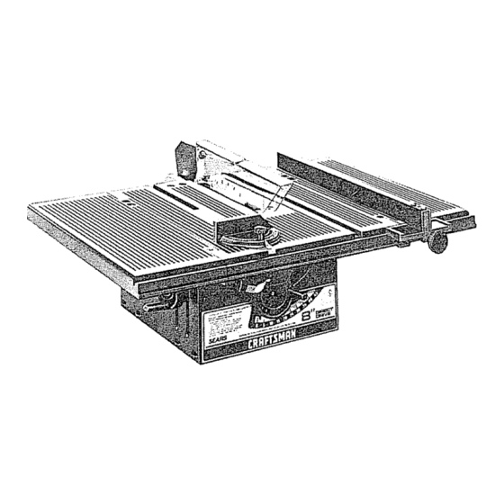
8 INCH
DIRECT
DRIVE
TABLE SA W
o assembly
® operating
o repair
parts
Sold
by SEARS,
ROEBUCK
AND
CO,,
Chicago,
IL
60684
U.S.A.
Part No, SP5022
Primed
i_ U S A
Advertisement
Table of Contents

Related Manuals for Craftsman 113.221611


Summary of Contents for Craftsman 113.221611
- Page 1 Save This Manual For Future Reference MODEL NO. 113.221611 Serial Number Model and serial number may be found at the rear of the base,, You should record both model and serial number in a safe place for future use, 8 INCH DIRECT DRIVE TABLE SA W...
-
Page 2: For Power Tools
FULL ONE YEAR WARRANTY ON CRAFTSMAN TABLE SAW If within one year from the date of purchase, this Craftsman Table Saw fails due to a defect in material or workmanship, Sears will repair it, free of charge WARRANTY SERVICE IS AVAILABLE... -
Page 3: For Table Saws
ADDITIONAL SAFETY INSTRUCTIONS FOR TABLE SAWS WARNING: FOR YOUR OWN SAFETY, DO NOT been damaged or broken ...such as the motor OPERATE YOUR SAW UNTIL IT IS COMPLETELY switch, or other operating control, a safety ASSEMBLED AND INSTALLED ACCORDING device or the power cord. cease operating THE INSTRUCTIONS,.. - Page 4 M NEVER usetheripfencewhencrosscutting or possible for the operation being performed the miter gaugewhenripping,DO NOTuse Keep all guards in place whenever possible the rip fenceasa lengthstop 12_ Do not use any blade or other culling tool Neverholdontoortouchthe"freeend"ofthe marked for an operating speed less than 3450 workpieceor a "free piece"that is cut off, RPM.
-
Page 5: Motor Specifications
MOTOR SPEC FICATIONS ELECTR!CAL REQUIREMENTS MOTOR SPECIFICATIONS the Canadian Standards Association The ground conductor has a green jacket and is attached to the The AC motor used in this saw is a non-reversible toot housing at one end and to the ground prong in type, with the following specifications: the attachment... -
Page 6: Table Of Contents
groundingtypeplugsand3-polereceptacles w hich The useof anyextension cordwill cause someloss acceptthe toolsplug. of power.To keepthistoa minimum andtoprevent over-heating andmotorburn-out,usethefollowing Extension Cord Length Wire Size A.W.G. tableto determinethe minimum wiresize(A.WoG) Up to 100 Ft ......extensioncord. 100-200 Ft ........200-400 Ft Useonly3 wireextension ¢ordswhichhave 3-prong .... -
Page 7: List Of Loose Parts
Model 1 ! 3 221611 Table Saw with Table Extensions is shipped complete in one carton Separate all parts from packing materials and check each one with the illustration and the list of Loose Parts to make certain alf items are accounted for, before discarding any packing material... -
Page 8: Adjusting Blade Insert
ADJUSTING BLADE INSERT 1 ,, Turn saw over 2, Loosen Phillips screw in blade insert do not remove, 3 Remove blade insert by lifting slightlyand pulling BLADE INSERT insert toward front of saw to disengage from key hole slot HEAD SCREW 4, Tab at rear of insert should engage in saw table... -
Page 9: Checking Heeling Or Parallelism Of
CHECKING HEELING OR PARALLELISM OF SAW BLADE TO MITER GAUGE GROOVE MARK 'X" ON TOOTH While cutting, the material must move in a straight line PARALLEL to the SAW BLADE . . therefore both the miter gauge GROOVE and the RIP FENCE must be PARALLEL to the SAW BLADE If the saw blade is not parallel to the miter gauge... -
Page 10: Adjusting
2 Fold a piece of cardboard or heavy paper over the blade to protect your hands 3 Grasp the blade and the cradle rod and move the mechani,sm right or left a small amount as needed to make the square touch the same amount front and rear Tighten one screw 4 Check... -
Page 11: Adjusting Bevel Pointer
ADJUSTING 90 DEGREE BEVEL STOP 1 On the stop bracket are two t0-32 pan head screws which set 90 ° stop position. If condition exists the two screws need to be turned clockwise to obtain 90 ° setting if condition B exists the stews should be turned counterclockwise I.,.,.,, - '_BLADE... -
Page 12: Degree Bevel Stop
CHECKING 45 DEGREE BEVEL STOP 1 Turn elevation handwheet clockwise to raise blade as high as it will go 2o Turn bevel handwheel clockwise to tilt blade to 45 ° 3 Lay head of combination square on the blade of square as illustrated and place head against the blade... -
Page 13: Aligning Table Extensions
3 Install left table extension install seven screws using 5/32 inch hex L wrench Just start screws ALIGNING TABLE EXTENSIONS NOTE; The table extensions must be the same height as the table and level, Place combination square on table and extension, BE SAME HEIGHT "-_ EXTENSION... -
Page 14: To Lower Extension
TO LOWER EXTENSION !. If extension is too high loosen four screws on underside of the extension D, E, F, and G. See illustration. 2 Tighten screws A, B and C on top of table extension to lower extension even with table top front and rear. -
Page 15: Aligning Table Extensions
ALIGNING TABLE EXTENSIONS WITH FRONT OF TABLE !, Place blade of combination square on front of table and table extension,, 2, Extension should line up with table, 'l'l='l'_'l'_'l'l'l'_'t'l'l'I'l'J'l,t'l'l'l'l't'l,l't,t I' I MOVE OUTER EDGE EXTENSION BACK 1 Loosen screws C and F in right extension illustration 2, Tighten screws B and G until extension... -
Page 16: Installing Blade Guard
SQUARE _.._ _..,_F SPREADER St'IPPORT TRUSS HEAD SPREADER BRACKET SCREW J" 5/8 IN LONG "_,_(7"_ K-_}_-"_'_.,. , _ SPREADER CLAMP INSTALLING BLADE GUARD SOCKET HEAD 1. From among the loose parts, find the hardware as SETSCREW _,_-_,_1_ "-_ (J'-- WING NUT shown "IL_&j 718 , ., Lo.a... -
Page 17: Aligning Spreader
6 Laya pieceof flat straightwoodandasquare on sawtableandrotatethe SPREADER S UPPORT until the bracketis alignedwith square 7 MAKE SURE END OF SUPPORT, B RACKET ANDRODAREEVEN.,+usingan1/8in+HexL wrench,TIGHTEN THESETSCREWS ONLY, ENDS OF SUPPORT AND BRACKET BE EVEN WITH END OF ROD TIGHTEN SETSCREW ONLY SPACE EQUAL TO APPROX 3 THICKNESSES OF PAPER... -
Page 18: Attaching Rip Fence
PIECE OF STRAIGHT WOOD "IGHTLY AGAINST HOLD WOOD 2, Installthe SPREADER CLAMP.Placespreader BLADE between spreaderclamp and bracket, Move forwarduntilallthreeareinline,TIGHTEN WING NUTS. 3 Lay a piece of straight flat wood againstthe sawblade. I nsertfoldedpaperbetween spreader andstrip of wood. 4,MAKESURETHE HEXNUTS UNDERNEATH ARELOOSE HOLD SPREADER 5 Lift the antikickbackpawlto clearthewoodand... -
Page 19: Aligning Rip Fence
12-3/4 REAR OF SAW 4 HOLES OPENING .312 DIA' MOUNTING SAW TO LEGS BENCH If you purchase Craftsman Steel Legs for your saw, assemble them according directions furnished with them If you mount the saw on any other bench, makesure... -
Page 20: Getting
GETTING TO KNOW YOUR 5 BLADE GUARD SPREADER 6 TABLE INSERT 8 SAW BLADE "k* RIP FENCE TABLE EXTENSION MITER GUAGE TABLE EXTENSION MITER GUAGE LOCK KNOB RIP FENCE LOCK KNOB TILT HANDWHEEL ,BEVEL SCALE BEVEL POINTER 2 ELEVATION HANDWHEEL POWER CORD 1 ON-OFF... -
Page 21: Elevation Handwheel
2. ELEVATION HANDWHEEL ,elevates orlowers D, Lift insert from front end, and pull toward front the blade, Turn counterclockwise to elevate of saw clockwise to lower NEVER OPERATE THE SAW WITHOUT 3. TILT HANDWHEEL tilts the blade for bevel PROPER INSERT IN PLACE. -
Page 22: To Install Saw Blade
3, Turn elevation handwheel clockwise to raise motor shaft as high as it will go, 4, Insert shaft wrench over flat portions of motor spacer and arbor wrench over arbor nut 5 Hold shaft wrench and loosen arbor nut with arbor wrench ARBOR WRENCH... -
Page 23: Work Helpers
BASIC SAW OPERATION USING MITER GAUGE CROSSCUTTING, MITER CUTTING, BEVEL by the back of the blade and thrown toward the CUTTING, COMPOUND MITER CUTTING operator), Stand to either side of the blade when RABBETING across the end of a narrow Keep your hands clear of the blade and out Of workpiece, the MITER GAUGE is used the path of the blade,... -
Page 24: Crosscutting
3/8 PLYWOOD 3/'4 PLYWOOD AUXILIARY FENCE Make one using a piece of 3/8 in,. and 3/4 in, plywood Fasten together with glue woodscrews NOTE: Since Push Block is used with Auxiliary Fence, the 4-3/4 in dimensions must be THIS FACE AND held identical on both the pieces. -
Page 25: Repetitive Cutting
REPETITIVE CUTTING REPETITIVE CUTTING is cutting a quantity pieces the same length without having to mark each piece NOTE: When making repetitive cuts from a long workpiece make sure it is supported 1 NEVER USE THE RIP FENCE AS A LENGTH STOP BECAUSE THE CUTOFF PIECE COULD BIND BETWEEN THE FENCE AND THE BLADE CAUSING... -
Page 26: Bevel Crosscutting
WORKPIECE BEVEL CROSSCUTTING BEVEL CROSSCUTTING is the same as cross- cutting except that the wood is cut at an angle TA!LE other than 90 ° with the flat side of the wood. Adjust the blade to the desired angle Use the Miter Gauge in the groove to the RIGHTof the blade It cannot be used in the groove to the... - Page 27 WORKPIECE RIPPING RIPPING is cutting a piece of wood with the grain, or lengthwise. This is done using the rip fence, Position the fence to the desired WIDTH OF RIP and TABLE lock in place Before starting to rip, be sure A, Rip Fence is parallel to sawblade.
- Page 28 When "WIDTH OF RIP" is 2 in, to 6 in, wide USE THE PUSH STICK to feed the work, When "WIDTH OF RIP" is NARROWER than 2 in,, the push stick CANNOT be used because the guard will interfere AUXILIARY FENCEIWORK SUPI_ORT and PUSH BLOCK Attach...
- Page 29 Narrow strips thicker than the Auxiliary Fence/Work Support may enter the guard and strike the baffle CAREFULLY raise guard only enough to clear the workpiece. Use PUSH BLOCK to complete cut. RESAWING RESAWlNG is a "thru-sawing" cut made by ripping a piece of wood through...
- Page 30 RABBETING RABBETING is known as cutting out a section of the FIRST corner of a piece of material, across an end or along RABB! an edge To make a RABBET requires cuts which do not go all the way through the material Therefore the blade...
- Page 31 Frequently blow out any dust that may accumulate inside the saw cabinet and the motor Frequently clean your cutting tools with Craftsman Gum and Pitch Remover A coat of automobile-type v,,=x applied to the table will hetp to...
-
Page 32: Lubrication
SAE Noo 20 or No, 30 engine oil 1_ Elevation guide slot and pivot 2, Elevation screw threads, 3., Bevel screw threads (First clean with Craftsman Gum & Pitch Remover.) 4 Bevel and elevation link pivot points 5 Cradle pivot pin bearing points... -
Page 33: Recommended
RECOMMENDED ACCESSORIES ITEM CAT. NO. ITEM CAT. NO, Saw Blades ......See Catalog Steel Legs ....... 9-22236 Retractable Caster Set ....9-22221 *Molding Head Set ...... 9-3222 Dado Insert ......9-22281 9-22222 "Power Tool Know How Handbook" Molding Insert ......9-22282 Table Saw ...... -
Page 34: Trouble
TROUBLE SHOOTING -- MOTOR NOTE: Motors used on wood-working tools are particulary susceptible to the accumulation sawdust and wood chips and should be blown out or '*vaccummed" frequently to prevent interferences with normal motor ventilation NOTE: The starting relay is a GRAVITY SENSITIVE TYPE NEVER TURN THE POWER ON WHILE THE SAW IS UPSIDE... - Page 35 REPAIR PARTS PARTS LIST FOR CRAFTSMAN 8 INCH DIRECT DRIVE TABLE MODEL NO. 113.221611 FIGURE 1 - GUARD ASSEMBLY 62935 Always Order by Part Number - Not by Key Number Part Description 62916 Link, Guard 62911 Guard 62519 Spring, Pawl...
- Page 36 PARTS LiST FOR CRAFTSMAN 8 lINCH DIRECT DRIVE TABLE MODEL NO. 113.221611 \ 65 f,,,t ¢P, 41-41.40...
- Page 37 PARTS LIST FOR CRAFTSMAN 8 INCH DIRECT DRIVE TABLE MODEL NO. 113.221611 FIGURE Part Part Description Description 60240 t_Nut, Push 3/8 62905 Bracket, Cradle 62912 Handwheel, 3-5/8 ST D601 'I03 *Screw, Hex Washer Hd STD551208 *Lockwasher, No 8 Type "T" 10-32 x 3/8...
- Page 38 PARTS LIST FOR CRAFTSMAN 8 INCH DIRECT DRIVE TABLE MODEL NO. 113,221611 FIGURE 3 - RIP FENCE ASSEMBLY 62937 Pa rt Description 62906 Channel, Fence STD522505 *Screw, Hex Hd, Sems 1/4-20 x 1/2 62985 Head, Fence 62482 Knob, t-1/4 Dia...
- Page 39 PARTS LIST FOR CRAFTSMAN 8 INCH DIRECT DRIVE TABLE SAW MODEL NO. 113.221611 FIGURE 4 - MITER GAUGE ASSEMBLY 62938 Part Description 62176 Knob, Miter Gauge STD551010 *Washer, I3/64 x 5/8 x 1/32 62173 Gauge, Miter 62175 Pin, Miter Pivot...
- Page 40 8 iNCH DIRECT DRIVE TABLE SERVICE Now that you have purchased your 8 inch direct drive table saw should a need ever exist for repair parts or service, simply contact any Sears Service Center and most Sears, Roebuck and Co stores Be sure to provide all pertinent...