
Related Manuals for Ericsson RX1290


Summary of Contents for Ericsson RX1290
- Page 1 RX1290 Multi-Format Receiver Software Version 3.0.0 (and later) REFERENCE GUIDE EN/LZT 790 0003/2 R1A...
- Page 2 The contents of this document are subject to revision without notice due to continued progress in methodology, design and manufacturing. Ericsson shall have no liability for any error or damage of any kind resulting from the use of this document.
- Page 3 Preliminary Pages Contents Chapter 1: Introduction This chapter identifies the equipment versions covered by this Reference Guide; describes the purpose of the equipment in a typical system; provides a summary of its main features; identifies the controls, indicators and connectors. Chapter 2: Installing the Equipment This chapter provides a guide to the suitability of an installation;...
-
Page 4: Revision History
3.0.0 Maintenance release. May 2008 3.0.0 References to New IP Card added. June 2011 3.0.0 Allocation of Ericsson Number Identity and re-brand completion. Associated Documents The following manuals/guides are also associated with this equipment: Ericsson Document Identity Original Document Title... - Page 5 Corporation. Trademarks ™ Alteia Trademark of Ericsson AB. Macrovision This product incorporates copyright protection technology that is protected by U.S. patents and other intellectual property rights. Use of this copyright protection technology must be authorized by Macrovision Corporation, and is intended for home and other limited viewing uses only unless authorized by Macrovision.
-
Page 6: Contact Information
Ericsson and your business. Warranty All Ericsson products and systems are designed and built to the highest standards and are covered under a comprehensive 12 month warranty. Levels of Continuing Ericsson Service Support For standalone equipment, then Ericsson BASIC Essential support is the value for money choice for you. - Page 7 Internet Address www.ericsson.com Technical Training Ericsson provides a wide range of training courses on the operation and maintenance of our products and on their supporting technologies. Ericsson can provide both regularly scheduled courses and training tailored to individual needs. Courses can be run either at your premises or at one of our dedicated training facilities.
- Page 8 Preliminary Pages Return of Equipment If you need to return equipment for repair please contact your local Ericsson Customer Services Department. Please refer to the Customer Services Contact Information on Page vii You will then be directed to return the faulty equipment to a repair centre with the appropriate facilities for that equipment.
-
Page 9: Table Of Contents
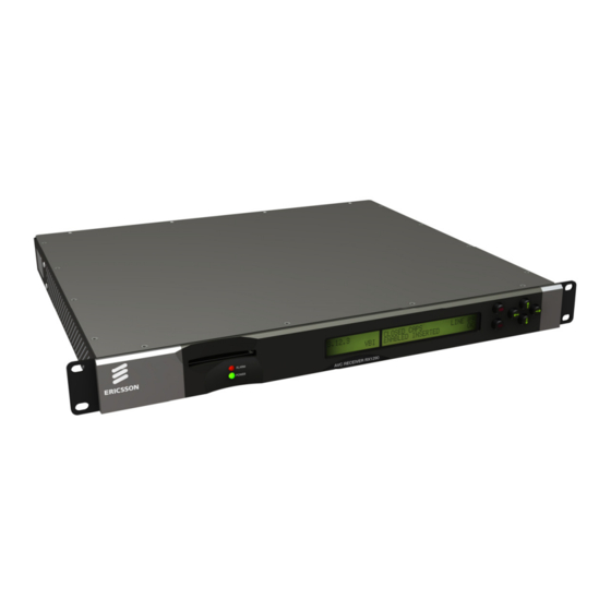
Introduction Chapter 1 Contents Scope of This Reference Guide ............1-3 1.1.1 Who Should Use This Reference Guide..........1-3 1.1.2 What Equipment is Covered by This Reference Guide ......1-3 1.1.2.1 The Equipment Models................. 1-3 1.1.2.2 Software Version .................. 1-5 Summary of Features ................ - Page 10 Introduction List of Figures Figure 1.1 Front View of a RX1290 Multi-Format Receiver........1-3 Figure 1.2 Typical Satellite Compression System ..........1-8 Figure 1.3 What the Satellite Receiver Does............1-9 Figure 1.4 Typical Compression System............. 1-10 Figure 1.5 Role of the Decoder ................1-11 Figure 1.6 Front Panel States ................
-
Page 11: Scope Of This Reference Guide
Maintenance information requiring the covers to be removed is not included. Warning! Do not remove the covers of this equipment. Hazardous voltages are present within this equipment and may be exposed if the covers are removed. Only Ericsson television trained and approved service engineers are permitted to service this equipment. -
Page 12: Table 1.2 Hardware Options
Introduction Table 1.2 Hardware Options Marketing Code Price Object Supply Object Description Number Number RX1290/HWO/DVBS2 FAZ 101 0116/3 ROA 128 3800 DVBS2 I/P SAT DEMOD OPTION RX1290/HWO/DVBS2/IF/C FAZ 101 0116/5 ROA 128 3801 DVBS2 I/P SAT DEMOD+CONST O/P RX1290/HWO/IP/PROFEC FAZ 101 0116/8 ROA 128 3802 IP, PRO-MPEG INPUT OPTION... -
Page 13: Software Version
Introduction Marketing Code Price Object Supply Object Description Number Number RX1290/SWO/LDELAY FAZ 101 0116/21 FAT 102 0223 LOW LATENCY DECODE MODE (4:2:0 ONLY) RX1290/SWO/HSETHER FAZ 101 0116/19 FAT 102 0224 HIGH SPEED DATA PIPING LICENSE RX1290/SWO/PAA FAZ 101 0116/25 FAT 102 0229 QUAD PHASE ALIGNED MPEG-1 LAYER 2 AUDIO RX1290/SWO/4AUD... - Page 14 Introduction Up to 40 preselected choices can be stored within the unit. • Multiple Inputs (Satellite Receivers): L-band Satellite Receivers have four inputs. • Video Decoding: MPEG 4:2:0 mode support. MPEG 4:2:2 mode support (MPEG-2 Only). • Audio Decoding: Sampling rate 48 kHz. All MPEG-1 data rates.
-
Page 15: Inputs
Introduction Front Panel User Interface. 1.2.2 Inputs 1.2.2.1 ASI Input (Decoder) One BNC connector supporting both byte-mode and single packet burst mode. 1.2.2.2 Remote Control An RJ-45 Ethernet connector for connection to a PC or network switch to provide SNMP control. 1.2.2.3 DVB-S / DVB-S2 L-Band Inputs (Satellite Receivers) (Option) Four F-type connectors connect the L-band output of a suitable LNB either directly... -
Page 16: Data Output
Typical Satellite System The Multi-Format Receiver is a component of the MPEG-4 AVC/MPEG-2/DVB compliant range of Ericsson's equipment. They are designed for use by broadcasters and distributors of video, audio and data Services over satellite. Figure 1.2 Typical Satellite Compression System... -
Page 17: Input Connections
Introduction 1.3.2 Input Connections The Satellite Receiver interfaces directly to Low-Noise Block (LNB) and accepts an intermediate frequency (IF) input in the band 950 - 2150 MHz (L-band) for operation in the specified symbol-rate range (see Annex B, Technical Specification). The unit can provide dc power and polarization switching to the LNB. -
Page 18: The Telco Receiver/Decoder
1.4.1 Typical Decoder System The Decoder is a component of Ericsson’s range of equipment. It is designed for use by broadcasters and distributors of video and audio Services. It can be used as a Transport Stream monitor or to decode signals received over a telecommunications network. -
Page 19: Control Modes
Introduction Figure 1.5 Role of the Decoder Control Modes 1.5.1 Introduction The Multi-Format Receiver is designed for unattended operation. Once set-up, the unit requires no further attention except to ensure the fans are working. There are up to three control modes associated with the Receiver (dependent upon options fitted). -
Page 20: Guided Tour
Introduction Guided Tour 1.6.1 Construction The Multi-Format Receiver is constructed using a screened self-ventilated modular system. All operational inputs and outputs are via rear-panel connectors. The unit may be operated freestanding or mounted in a 19-inch rack. 1.6.2 Front Panel Controls The physical interface for the Front Panel consists of an alphanumeric LCD display, pushbuttons, and status LEDs that are used to set-up and monitor the unit. -
Page 21: Rear Panel
Introduction 1.6.4 Rear Panel Inputs and outputs to the unit are taken via the rear panel. Connector descriptions are given in Chapter 2, Installing the Equipment and Chapter 6, Options. EN/LZT 790 0003/2 R1A 1-13... - Page 22 Introduction BLANK 1-14 EN/LZT 790 0003/2 R1A...
- Page 23 Installing the Equipment Chapter 2 Contents Read This First! ..................2-3 2.1.1 Handling ....................2-3 2.1.2 Installing the Equipment ............... 2-3 2.1.3 Lifting ....................2-3 2.1.4 Site Requirements ................2-3 2.1.4.1 Power Supplies..................2-3 2.1.4.2 Environment ..................2-3 2.1.4.3 Lightning Protection................2-3 Preliminary Checks................
- Page 24 Installing the Equipment 2.7.9 Alarm Connector and Relay ............... 2-15 2.7.10 RS-232 Low-speed Asynchronous Data Output ........ 2-15 2.7.11 Serial Remote Control ................ 2-16 Option Card Connectors..............2-16 List of Figures Figure 2.1 Air-flow Through the Equipment............2-5 Figure 2.2 AC Power Inlet Assembly..............2-7 Figure 2.3 Location of the Technical Earth............
-
Page 25: Read This First
Installing the Equipment Ensure the personnel designated to fit the unit have the appropriate skills and knowledge. If in any doubt, contact Ericsson Customer Services (see Preliminary Pages for contact details). Installation of the product should follow these instructions, and should only use installation accessories recommended by the manufacturers. -
Page 26: Preliminary Checks
The product may fall, causing serious injury and serious damage to the product. Use only with a cart, stand, bracket or table recommended by Ericsson. An appliance and cart combination should be moved with care. Quick stops, excessive force, and uneven surfaces may cause the appliance and cart combination to overturn. -
Page 27: Ventilation
Installing the Equipment 2.3.2 Ventilation 2.3.3 Openings in the Covers Side openings in the unit, as well as side-mounted cooling fans, are provided for ventilation. They ensure reliable operation of the product and protect it from overheating. The openings of the fans must not be blocked or covered. Air is released through vents at this side of the unit. -
Page 28: Installing Cables - Safety
Installing the Equipment 2.3.4 Installing Cables - Safety Power supply cables should be routed so that they are not likely to be walked on or pinched by items placed upon or against them. Pay particular attention to cables at plugs, convenience receptacles, and the point where they exit from the appliance. Do not run AC power cables in the same duct as signal leads. -
Page 29: Ac Power Supply Cord
Installing the Equipment Warning! The RX1290 should only be operated from the type of power source indicated on the marking label. If you are not sure of the type to your business, consult your appliance dealer or local power company. Do not overload wall outlets and extension cords as this can result in a risk of fire or electric shock. -
Page 30: Connecting The Equipment To The Ac Power Supply
This unit must be correctly earthed through the molded plug supplied. If the local mains supply does not have an earth conductor do not connect the unit. Contact Ericsson Customer Services for advice. Before connecting the unit to the supply, check the supply requirements in Annex B. -
Page 31: Signal Connections
Installing the Equipment Technical Earth Figure 2.3 Location of the Technical Earth Signal Connections 2.7.1 General Caution! It is strongly recommended that the terminal marked at the rear panel of the equipment is connected to a site Technical Earth before any external connections are made and the equipment is powered. - Page 32 Installing the Equipment RX1290 Multi-Format Receiver Motherboard RX1290/BAS ASI/HDSDI/SDSDI OUT 1 Transport Stream/Digital Video Output ASI/HDSDI/SDSDI OUT 2 Transport Stream/Digital Video Output ASI/HDSDI/SDSDI OUT 3 Transport Stream/Digital Video Output ASI In AUDIO 1 Analogue/Digital Audio Output AUDIO 2 Analogue/Digital Audio Output FRAME SYNC Frame Synchronization CVBS OUT...
-
Page 33: Asi/Hd-Sdi/Sd-Sdi Out
Installing the Equipment 2.7.2 ASI/HD-SDI/SD-SDI OUT The unit has three ASI/SMPTE 292M video (HD-SDI)/656 video (SD-SDI) outputs in the standard configuration. ASI/HD-SDI/SD-SDI OUT 1/2/3 The output standard must be selected from the user interface or remote control interface. The ASI/HD-SDI/SD-SDI output is coaxial via BNC connectors. Video control is through the Video Menu (Menu 3.1). -
Page 34: Svga Output (Rgb Hv)
Installing the Equipment In addition, four unbalanced digital audio outputs are available via separate BNC connectors. Table 2.5 Analogue/Digital Audio Connectors AUD 1 Item Specification Connector type 9-way, D-type, Male Connector AUDIO 1 designations AUDIO 2 Pin-outs Pin 1 - Digital audio + Pin 2 - Ground Pin 3 - Left + Pin 4 - Right +... -
Page 35: Frame Synchronization
Installing the Equipment Table 2.7 SVGA Connector Item Specification Connector type 15-way D-type Connector Video Out designation Pin-outs Red / Pr 75 Ω, 0,7Vt-t Green / Y 75 Ω, 0,7Vt-t Blue / Pb 75 Ω, 0,7Vt-t Video GND Red GND Green GND Blue GND Sync GND... -
Page 36: Ethernet
Installing the Equipment Table 2.8 Frame Sync Hi-Z Connector Item Specification BNC 75 Ω socket Connector type Connector FRAME SYNC designation Pin: Centre Analogue Black and Burst Input Shield Ground/Chassis Last unit must be terminated with 75 Ω Impedance 2.7.7 Ethernet The equipment has an Ethernet remote control port for SNMP Control. -
Page 37: Alarm Connector And Relay
Installing the Equipment 2.7.9 Alarm Connector and Relay The alarm relay connector has a summary relay. The summary relay is activated whenever the unit detects an ALARM RELAY alarm, or the power is switched off. Table 2.11 Alarm Connector Item Specification Connector type 9-way, D-type, Female for the summary alarm... -
Page 38: Option Card Connectors
Installing the Equipment Item Specification Pin 5 - Ground (RS-232) Pin 6 - Reserved Pin 7 - No connection Pin 8 - Reserved Pin 9 - Reserved 2.7.11 Serial Remote Control A 9-way, D-type male connector provides a configurable RS232/RS485 asynchronous low-speed data serial RS232/RS485 REMOTE communications interface for remote control. - Page 39 Operating the Equipment Locally Chapter 3 Contents Powering the Equipment ..............3-5 3.1.1 Switching On ..................3-5 3.1.2 Power up Operating Modes ..............3-5 Front Panel Controls and Pushbuttons..........3-6 Front Panel Operating Modes .............. 3-6 3.3.1 General....................3-6 3.3.2 Navigate Mode ..................
- Page 40 Operating the Equipment Locally 3.7.12 Setting Up VITC ................. 3-19 3.7.13 Setting Up Closed Captions ............... 3-20 3.7.14 Setting Up ITS Insertion ..............3-20 3.7.15 Setting Up VPS .................. 3-20 3.7.16 Setting Up WSS ................. 3-20 3.7.17 Setting Up Video Index............... 3-21 3.7.18 Setting Up Monochrome Samples............
- Page 41 Table 3.13 Setting Aspect Ratio ................3-16 Table 3.14 Setting Video Delay Mode ..............3-16 Table 3.15 Setting Video Ddelay Mode ..............3-16 Table 3.16 Setting Low delay mode ..............3-17 Table 3.17 Manually Selecting the Audio Components ........3-17 Table 3.18 Setting Up Async Data ...............
- Page 42 Operating the Equipment Locally BLANK EN/LZT 790 0003/2 R1A...
-
Page 43: Powering The Equipment
Operating the Equipment Locally Powering the Equipment 3.1.1 Switching On Caution! This equipment should not be operated unless the cooling fan is working and there is free-air flow around the unit. Connect the signal inputs and AC power supply to the Multi-Format Receiver and power up the unit. -
Page 44: Front Panel Controls And Pushbuttons
Operating the Equipment Locally Front Panel Controls and Pushbuttons Front Panel items are described under Section 1.6, Guided Tour. ALARM LED LCD display Edit Left POWER LED Save Down Right Figure 3.2 Front Panel Controls and Pushbuttons Front Panel Operating Modes 3.3.1 General Operating the Multi-Format Receiver from the Front Panel is via two operating... -
Page 45: Edit Mode
Operating the Equipment Locally Pushbutton LEDs will be updated to indicate which pushbutton presses are still valid as each navigation pushbutton press event is processed. For example, a lit Up pushbutton LED indicates there are pages above the current one. 3.3.3 Edit Mode Edit mode edits the right display area and allows the user to alter control... -
Page 46: Selecting A Menu Option
Operating the Equipment Locally 3.4.2 Selecting a Menu Option Some items shown in the right display area of the front panel LCD display have a set number of options. An example of this is the VIDEO TEST PATTERN (Menu 3.1.6) which has a number of preset Video Test Patterns associated with it. Use the following steps as a general guide to selecting an option. -
Page 47: Setting Up Preset Services (Menu 1)
Operating the Equipment Locally Setting Up Preset Services (Menu 1) 3.5.1 Using Preset Services This group allows up to 40 Services to be stored as presets. Selecting a Service from the preset list in Menu 1 automatically reconfigures the Multi-Format Receiver to receive that Service with its associated parameters set as stored. -
Page 48: Setting Up The Input (Menu 2)
Operating the Equipment Locally Setting Up the Input (Menu 2) 3.6.1 DVB-S2 Satellite Receiver (TT1290/HWO/DVBS2 and TT1290/HWO/DVBS2/IF/CONST) Table 3.6 Setting Up the DVB-S2 Satellite Receiver Step Action Result Go to Menu 2.3 and select The Receiver can take its signals from four SOURCE 1. -
Page 49: Dvb-S2 Input Option Card Tt1290/Hwo/Dvbs2/If/Const
Operating the Equipment Locally 3.6.1.1 DVB-S2 Input Option Card TT1290/HWO/DVBS2/IF/CONST The DVB-S2 demod option TT1290/HWO/DVBS2/IF/CONST offers three L-band inputs plus an IF input. If this input option card is fitted in the receiver then note that Menu 2.3.5 sets the IF input frequency. LNB Frequency, Satellite Frequency and LNB Power parameters are not applicable for this input. -
Page 50: 10/100Baset Input - Rx1290/Hwo/Ip
Operating the Equipment Locally 3.6.3 10/100BaseT Input – RX1290/HWO/IP Table 3.8 steps through the set-up procedure of the Telco Receiver using Menu 2 Input, and the IP input. Table 3.8 Setting Up the IP Interface Step Action Result Connect the Ethernet cable to the IP input connector. -
Page 51: 100/1000Baset Dual Ip Input - Rx1290/Hwo/Gige
Operating the Equipment Locally 3.6.4 100/1000BaseT Dual IP Input – RX1290/HWO/GIGE Steps through the set-up procedure of the Receiver using Menu 2 Input, and the IP input. Table 3.9 Setting Up the Dual IP Interface Step Action Result Connect the Ethernet cables to the IP input connectors. -
Page 52: Service Configuration (Menu 3)
Operating the Equipment Locally Step Action Result Return to Input Menu 2, it should display the current status. If status is NOT LOCKED, verify that the cable is properly connected and that all values have been entered correctly. Service Configuration (Menu 3) 3.7.1 Selecting and Setting Up a Service Each Transport Stream may contain many Services. -
Page 53: Setting Down Conversion Mode
Operating the Equipment Locally Step Action Result Scroll to Menu 3.1.7 and edit Edits the video test pattern to be displayed. the video test pattern to be displayed. Press Save. Scroll to Menu 3.1.10 and edit Edits the parameter for framesync enable. the parameter for framesync enable (ENABLED or DISABLED). -
Page 54: Setting Video Delay
Operating the Equipment Locally Table 3.13 Setting Aspect Ratio Step Action Result Scroll to Menu 3.1.9 and edit Edits the parameter for the output SD aspect the parameter for aspect ratio ratio. (4:3, or 16:9). Press Save. 3.7.5 Setting Video Delay This menu allows the user to vary the output presentation delay. -
Page 55: Selecting The Audio Component
Operating the Equipment Locally Table 3.16 Setting Low delay mode Step Action Result Go to Menu 3.1.15 and edit Gains access to the low delay option. There is a the option displayed. (LOW choice between low delay and normal mode. DELAY MODE, NORMAL). -
Page 56: Setting Up Asynchronous Data (Rs-232)
Operating the Equipment Locally Step Action Result Scroll to Menu 3.3.4 and edit the Edits the Audio 1 digital output format and Audio 1 digital output format output routing. (AES3 or AC-3) and output Note that when the input signal is STEREO, routing (STEREO, MIXED TO the Audio digital output format will always be BOTH, LEFT TO BOTH, or... -
Page 57: Setting Up Teletext
Operating the Equipment Locally Step Action Result Scroll to Menu 3.8.1 and edit The unit receives and displays the correct bit- the High speed data output rate. (ENABLED or DISABLED). Press Save. Scroll to Menu 3.8.3 and edit If the Forward to Gateway option is turned on, the Forward to Gateway the unit will forward the data stream to the ON/OFF and the Gateway IP... -
Page 58: Setting Up Closed Captions
Operating the Equipment Locally 3.7.13 Setting Up Closed Captions Table 3.22 Setting Up Closed Captions Step Action Result Scroll to Menu 3.10.3 and edit Edits the parameter for enabling Closed the parameter for enabling Captions pass-through. Closed Captions pass-through (ENABLED or DISABLED). Press Save. -
Page 59: Setting Up Video Index
Operating the Equipment Locally 3.7.17 Setting Up Video Index Table 3.26 Setting Up Video Index Step Action Result Scroll down to Menu 3.10.7 Edits the parameter for enabling Video Index and edit the parameter for pass-through. enabling Video Index insertion (ENABLED or DISABLED). -
Page 60: Setting Up Vanc Data Insertion
Operating the Equipment Locally 3.7.21 Setting Up VANC Data Insertion Table 3.30 Setting Up VANC Data Insertion Step Action Result Scroll down to Menu 3.11.1 Edits the parameter for enabling VANC Data and edit the parameter for insertion. enabling VANC Data insertion PLEASE NOTE: Any data passed by this (ENABLED or DISABLED). -
Page 61: Setting Up Dvb Subtitles
Operating the Equipment Locally 3.7.25 Setting Up DVB Subtitles Table 3.34 Setting Up DVB Subtitles Step Action Result Scroll down to Menu 3.15.1 Edits the parameter for enabling DVB Subtitles. and edit the parameter for PLEASE NOTE: This feature is only supported enabling DVB Subtitles for SD 4:2:0 video sources only. -
Page 62: Basic Interoperable Scrambling System (Biss) (Menu 4.4)
Operating the Equipment Locally 3.8.2 Basic Interoperable Scrambling System (BISS) (Menu 4.4) BISS Mode 1 is similar to RAS in that it uses a fixed control word to encrypt the data in the transport stream. Unlike RAS, the scrambling algorithm is non-proprietary, using the DVB Common Scrambling Algorithm to allow interoperability with other manufacturers’... -
Page 63: Setting Up The Transport Stream Output (Menu 5)
Operating the Equipment Locally Setting Up the Transport Stream Output (Menu 5) 3.9.1 Set-Up Procedure Use Table 3.37 to step through the Transport Stream Output set-up procedure using Menu 5. This allows the Transport Stream for the current Service to be output on the ASI output connectors. -
Page 64: Transport Stream Output Bit-Rates
Operating the Equipment Locally 3.9.3 Transport Stream Output Bit-rates The Maximum input/output rates are described in Table 3.39. Table 3.39 Maximum Descrambled Transport Stream Output Bit-rates Level of TSO Setting Input Output Descrambling None POST INPUT 160 Mbps 160 Mbps Common Interface, POST TS 100 Mbps... -
Page 65: Setting Up System Parameters (Menu 7)
Operating the Equipment Locally Step Action Result Scroll to Menu 6.4 and edit the Edits the Audio 2 alarms menu. AUDIO 2 menu (NO ALARM, SET ALARM ONLY). Press Save. Scroll to Menu 6.5 and edit the Edits the Audio 3 alarms menu. AUDIO 3 menu (NO ALARM, SET ALARM ONLY). -
Page 66: Restarting The Unit
Operating the Equipment Locally Step Action Result Scroll to Menu 7.1.3.1 and edit the Edits the Subnet Mask. Subnet Mask. Press Save. Scroll to Menu 7.1.3.2 and edit the Edits the Gateway address. Gateway address. Press Save. Scroll to Menu 7.1.4 and Edits the Restore System Defaults menu. - Page 67 Operating the Equipment Remotely Chapter 4 Contents Remote Control ..................4-3 4.1.1 Introduction................... 4-3 4.1.2 Remote Protocol Control Documentation ..........4-3 4.1.3 Configuring the Unit for Remote Control via SNMP Port ...... 4-3 4.1.4 Configuring the Unit for Remote Control Via the Serial Remote Port ... 4-3 4.1.5 Configuring the Unit for Remote Control Over-air ........
- Page 68 Operating the Equipment Remotely BLANK EN/LZT 790 0003/2 R1A...
-
Page 69: Remote Control
The unit is ready for Remote Control. Note: The remote control protocols are not contained as a part of the product. An additional license fee, NDA or other agreement with Ericsson may be necessary to obtain the information required to control the product remotely. 4.1.4... -
Page 70: Configuring The Unit For Remote Control Over-Air
Operating the Equipment Remotely Table 4.2 Configuring the Serial Remote Port and Activating Remote Protocol Step Action Result Go to menu 7.1. Displays ‘OPERATING MODE’. Press Edit. Displays ‘FRONT PANEL’. Press the down pushbutton The settings should be set to match the external and select ‘SERIAL REMOTE’. -
Page 71: Entering The Oac Lockout Pin
Caution! Ericsson Customer Services Help Desk will not be able to provide you with the Local lockout PIN, as it is uniquely created at the time of the lockout. The user creates the PIN at lockout time. To obtain the PIN, please consult the person responsible for the administration of the unit. - Page 72 Operating the Equipment Remotely BLANK EN/LZT 790 0003/2 R1A...
- Page 73 Alarms Chapter 5 Contents Introduction................... 5-3 Location of the Alarm and Power LEDs..........5-3 Alarm LED .................... 5-3 List of Figures Figure 5.1 Front Panel LEDs ................. 5-3 EN/LZT 790 0003/2 R1A...
- Page 74 Alarms BLANK EN/LZT 790 0003/2 R1A...
-
Page 75: Alarm Led
Alarms Introduction There are two Front Panel LEDs that indicate the status of the Multi-Format Receiver. These are used to indicate abnormal performance of the unit. Location of the Alarm and Power LEDs The red ALARM LED is used to indicate an equipment fault condition, for example a missing or faulty input signal. - Page 76 Alarms • Audio 3 not running - This alarm is raised if the third audio is incorrect. • Audio 4 not running - This alarm is raised if the forth audio is incorrect. • Unit temperature - This alarm is raised if the unit exceeds an internal temperature of +65 It is possible to signal additional alarms depending on the Transport Stream input type and optional functionality in the unit.
- Page 77 Options Chapter 6 Contents Hardware Enabled Options ..............6-3 DVB-S2 Input Cards (RX1290/HWO/DVBS2 and RX1290/HWO/DVBS2/IF/CONST) ............6-3 6.2.1 General....................6-3 6.2.2 Connector Details - L-Band Inputs ............6-3 6.2.3 Connector Details – IF Monitor Input (RX1290/HWO/DVBS2/IF/CONST) ............6-4 6.2.4 Connector Details – Constellation Output (RX1290/HWO/DVBS2/IF/CONST) ............
- Page 78 Options List of Figures Figure 6.1 The Protocol Stack ................6-6 Figure 6.2 Building the Ethernet Frame..............6-6 List of Tables Table 6.1 DVB-S2 Satellite Receiver (L-band) Connector ........6-4 Table 6.2 DVB-S2 Satellite Receiver (IF Monitor Input) Connector ..... 6-4 Table 6.3 DVB-S2 Satellite Receiver (Constellation Output) Connector....
-
Page 79: Hardware Enabled Options
Options Hardware Enabled Options These options require extra hardware to be fitted to the unit. Contact the Customer Services Helpdesk for details (see Preliminary Pages). DVB-S2 Input Cards (RX1290/HWO/DVBS2 and RX1290/HWO/DVBS2/IF/CONST) 6.2.1 General The DVB-S2 Input card supports DVB-S, QPSK demodulation and DVB-S2, QPSK and 8PSK demodulation. -
Page 80: Connector Details - If Monitor Input (Rx1290/Hwo/Dvbs2/If/Const)
Options Table 6.1 DVB-S2 Satellite Receiver (L-band) Connector Input Specification Connector Type F-type, Female Connector designation IN 1, IN 2, IN 3, IN 4 3 x L-band inputs only on RX1290/HWO/DVBS2/IF/CONST Pin: Centre RF Input Shield Ground/Chassis LNB Supply Refer to the next caution box 75 Ω... -
Page 81: Connector Details - Constellation Output (Rx1290/Hwo/Dvbs2/If/Const)
Options 6.2.4 Connector Details – Constellation Output (RX1290/HWO/DVBS2/IF/CONST) Connect the I and Q constellation output connectors to a suitable display device such as an oscilloscope set to X-Y mode. I/Q Output Constellation output is enabled using the Input Status Menu (Menu 2). - Page 82 Options MPEG-2 Transport Stream Control traffic for in-band (Multi-Program Transport management Stream or Single-Program (telnet, http, snmp) Transport Stream) MPEG-2/DVB layer TCP/UDP UDP – User Datagram Protocol Transport layer - IP Link layer – 10/100BaseT Ethernet Figure 6.1 The Protocol Stack The MPEG-2/DVB layer is specified in ISO/IEC IS 13818 –...
-
Page 83: 100/1000Baset Dual Ip Input - Rx1290/Hwo/Gige
Options 100/1000BaseT Dual IP Input – RX1290/HWO/GIGE Dual IP NIC Input card provides a 100/1000BaseT Ethernet port, on which a transport stream can be received in UDP packets at up to 208 Mbps. The card can receive RTP encapsulated transport streams. RTP encapsulation provides a more robust transport stream than UDP encapsulation. -
Page 84: Mode Of Operation When Input Port Is Set To Port 1 Or Port 2
Options 6.5.1.2 Mode of Operation when input port is set to Port 1 or Port 2 When the user sets the input port to either port 1 or port 2, a link down or TS lock drop does not cause any switch over to the other port. This mode of operation is the manual mode where the user decides what port is being used regardless of the status of the link. -
Page 85: Mpeg-2 Hd 4:2:2 Decode (Rx1290/Swo/Mpeg-2/Hd/422)
Options 6.11 MPEG-2 HD 4:2:2 Decode (RX1290/SWO/MPEG- 2/HD/422) This option enables MPEG-2 HD 4:2:2 decode functionality. 6.12 MPEG-4 SD Decode (RX1290/SWO/MPEG4/SD) This option enables MPEG-2 HD decode functionality. 6.13 MPEG-4 HD, SD MPEG-2, HD 4:2:2 Decode (RX1290/SWO/MPEG-4/HD) This option enables H.264 HD and SD and MPEG-2 HD 4:2:2 decode functionality. 6.14 DVB-S2 QPSK (RX1290/SWO/DVBS2/QPSK) This option enables the DVB-S2 demodulator option card QPSK demodulation... -
Page 86: Aac Audio Support (Rx1290/Swo/Aac)
Options 6.19 AAC Audio Support (RX1290/SWO/AAC) This option enables AAC audio decode support on the receiver. 6.20 Down Conversion (RX1290/SWO/DCONV) This option enables down conversion of HD to SD video on the receiver. 6.21 Common Interface (RX1290/SWO/CI) This option enables Common Interface descrambling support on the receiver. 6.22 Provider Lock (RX1290/SWO/PROV/LOCK) This provides the option to support Provider Lock. - Page 87 Checks on Completion of Servicing............7-4 Maintenance and Support Services............7-5 7.4.1 Introduction................... 7-5 7.4.2 Warranty ....................7-5 7.4.3 Levels of Continuing Ericsson Service Support........7-5 7.4.4 Warranty ....................7-5 7.4.4.1 Levels of Continuing Ericsson Service Support........7-5 Fault-finding..................7-6 7.5.1 General....................
- Page 88 Preventive Maintenance and Fault-finding BLANK EN/LZT 790 0003/2 R1A...
-
Page 89: Introduction
Preventive Maintenance and Fault-finding Introduction This chapter provides the schedules and instructions, where applicable, for routine inspection, cleaning and maintenance which should be performed by an operator. There are also some basic fault-finding procedures to follow in the event of a suspected failure of the RX1290 Multi-Format Receiver. -
Page 90: Servicing
7. If the equipment has been subject to a lightning strike or power surge. 7.3.2 Replacement Parts When replacement parts are required, be sure only parts specified by Ericsson (or having the same characteristics as the original part) have been used. Unauthorized substitutions may result in fire, electric shock or other hazards. -
Page 91: Maintenance And Support Services
Ericsson and your business. 7.4.2 Warranty All Ericsson products and systems are designed and built to the highest standards and are covered under a comprehensive 12 month warranty. 7.4.3 Levels of Continuing Ericsson Service Support For standalone equipment, then Ericsson BASIC Essential support is the value for money choice for you. -
Page 92: Fault-Finding
Preventive Maintenance and Fault-finding Fault-finding 7.5.1 General The information contained in this chapter is intended to isolate the unit as the faulty equipment if a system failure occurs. If the following information fails to clear the abnormal condition, please contact Customer Services using the information given in the Preliminary Pages of this manual. -
Page 93: Ac User Accessible Fuse Replacement
Preventive Maintenance and Fault-finding AC User Accessible Fuse Replacement Caution! This product should be operated only from the type of power source indicated on the marking label. If you are not sure of the type of power supply to your home or business, consult your appliance dealer or local power company. -
Page 94: Disposal
Preventive Maintenance and Fault-finding Caution! When replacing the power input fuse, always ensure that a fuse of the correct type and rating is fitted. Failure to do so results in inadequate protection. 3. Replace the fuse in the carrier. 4. Insert the fuse carrier back in the AC power inlet. AC Power Inlet To access the fuse, ease out the notch with a small flat-blade... - Page 95 Glossary Annex A The following list covers most of the abbreviations, acronyms and terms as used in Ericsson Manuals, User and Reference Guides. All terms may not be included in this Reference Guide. μm Micrometer (former name - micron): a unit of length equal to one millionth (10-6) of a meter.
- Page 96 Glossary AMOL I and II Automatic Measure of Line-ups I and II: Used by automated equipment to measure programme-viewing ratings. Address Resolution Protocol. A protocol used to "resolve" IP addresses into underlying Ethernet MAC addresses. Asynchronous Serial Interface. ASIC Application-Specific Integrated Circuit: A customized chip designed to perform a specific function.
- Page 97 Glossary Bouquet A collection of services (TV, radio, and data, or any combination of the three) grouped and sold together, and identified in the SI as a group. A single service may be in several bouquets. B-Picture; B-Frame Bi-directionally Predictive Coded Picture/Frame: A picture that is coded using motion-compensated prediction from previous I or P frames (forward prediction) and/or future I or P frames (backward prediction).
- Page 98 Glossary Chrominance The color part of a TV picture signal, relating to the hue and saturation but not to the luminance (brightness) of the signal. In a composite-coded color system, the color information (chrominance, often referred to as chroma) is modulated onto a high frequency carrier and added to the monochrome-format video signal carrying the luminance (Y).
- Page 99 Glossary Data Communications Equipment: Typically a modem. It establishes, maintains and terminates a session on a network but in itself is not the source (originator) or destination (end receiving unit) of signals (e.g. a computer, see DTE). A DCE device may also convert signals to comply with the transmission path (network) format.
- Page 100 Glossary DSNG Digital Satellite News-Gathering. Digital Signal Processor. Data circuit Terminating Equipment: A communications device that originates (is the source) or is the end receiving unit (destination) of signals on a network. It is typically a terminal or computer. Direct-To-Home. The term used to describe uninterrupted transmission from the satellite directly to the subscriber, that is, no intermediary cable or terrestrial network utilized.
- Page 101 Group of Pictures: MPEG video compression works more effectively by processing a number of video frames as a block. The Ericsson AB Encoder normally uses a 12 frame GOP; every twelfth frame is an I frame.
- Page 102 Glossary Graphical User Interface: The use of pictures rather than just words to represent the input and output of a program. A program with a GUI runs under a windowing system and has a screen interface capable of displaying graphics in the form of icons, drop-down menus and a movable pointer.
- Page 103 Glossary Internet Protocol: The IP part of TCP/IP. IP implements the network layer (layer 3) of the protocol, which contains a network address and is used to route a message to a different network or sub-network. IP accepts packets from the layer 4 transport protocol (TCP or UDP), adds its own header to it and delivers a datagram to the layer 2 data link protocol.
- Page 104 Glossary JPEG Joint Photographic Experts Group: ISO/ITU standard for compressing still images. It has a high compression capability. Using discrete cosine transform, it provides user specified compression ratios up to around 100:1 (there is a trade-off between image quality and file size). kbps 1000 bits per second.
- Page 105 Glossary Multiplex Element Manager: A GUI-based control system, part of the range of Ericsson AB compression system control element products. The evolution 5000 MEM holds a model of the system hardware. Using this model, it controls the individual system elements to configure the output multiplexes from the incoming elementary streams.
- Page 106 Glossary Multicast An IP mechanism that allows transmission of data to multiple receivers. A multicast can also have several transmit sources simultaneously. In video applications, multicast is typically used to distribute a video signal from a central source to multiple destinations.
- Page 107 Glossary OFDM Orthogonal Frequency Division Multiplex: A modulation technique used for digital TV transmission in Europe, Japan and Australia; more spectrally efficient than FDM. In OFDM, data is distributed over a large number of carriers spaced apart at precise frequencies. The carriers are arranged with overlapping sidebands in such a way that the signals can be received without adjacent channel interference.
- Page 108 Glossary Packetized Elementary Stream: A sequential stream of data bytes that has been converted from original elementary streams of audio and video access units and transported as packets. Each PES packet consists of a header and a payload of variable length and subject to a maximum of 64 kbytes.
- Page 109 Data may be written to, or read from, the device as often as required. When power is removed, the data it contains is lost. Remote Authorization System: A Ericsson AB proprietary public-key encryption system used to prevent unauthorized viewing of a TV programme or programmes.
- Page 110 Glossary Read Only Memory: A non-volatile storage device for digital data. Data has been stored permanently in this device. No further information may be stored (written) there and the data it holds cannot be erased. Data may be read as often as required. Reed-Solomon coding: An error detection and correction, coding system.
- Page 111 Glossary Set-Top Box: A box that sits on top of a television set and is the interface between the home television and the cable TV company. New technologies evolving for set-top boxes are video-on-demand, video games, educational services, database searches, and home shopping.
- Page 112 Glossary SNTP Simple Network Time Protocol is an Internet protocol used to synchronize the clocks of computers to some time reference. It is a simplified version of the protocol NTP protocol which is too complicated for many systems. Spatial Redundancy Information repetition due to areas of similar luminance and/or chrominance characteristics within a single frame.
- Page 113 Glossary UART Universal Asynchronous Receiver Transmitter: A device providing a serial interface for transmitting and receiving data. User Datagram Protocol. A protocol above the IP layer that provides port multiplexing in addition. In essence, you can transmit IP data packets to several receiving processes in the same unit/device. Unicast Point-to-point connection, i.e.
- Page 114 Glossary Y (Luminance) Defines the brightness of a particular point on a TV line. The only signal required for black and white pictures. Broadcast video with separate color, Y (luminance) and C (Chroma) (sometimes called S-Video). Y: Luminance component (Brightness), U and V: Chrominance (Color difference) A-20 EN/LZT 790 0003/2 R1A...
-
Page 115: Technical Specification
Technical Specification Annex B Contents Output....................B-3 B.1.1 Supported Video Resolutions ...............B-3 B.1.2 Supported Video Bit-rates ..............B-3 B.1.3 Composite Video Output ..............B-3 B.1.4 Performance Figures ................B-5 B.1.5 HD SDI ....................B-6 Audio Decoding and Output Stage ............B-7 B.2.1 General....................B-7 B.2.2 MPEG Audio..................B-7 B.2.3 Dolby Digital AC-3 Audio ..............B-7 B.2.4... - Page 116 Technical Specification B.5.4 SNMP Remote Control Connector ............. B-21 B.5.5 Alarm Connector ................B-21 Environmental ..................B-22 B.6.1 Conditions ..................B-22 Compliance ..................B-22 Safety ....................B-22 B.8.1 EMC ....................B-23 B.8.2 Telecommunications ................B-23 B.8.3 CE Marking ..................B-23 B.8.4 C-Tick Mark ..................
-
Page 117: Output
Technical Specification Output B.1.1 Supported Video Resolutions The Multi-Format Receiver supports H.264, 4:2:0 and 4:2:2. Table B.1 Supported Video Resolutions Input Resolutions Frame Output Format Specification (H x V) Rates (H x V) 1920 x 1080 1920 x 1080 SMPTE 274M interlaced 1440 x 1080 29.97... - Page 118 Technical Specification Table B.3 625 Line Description Test Signal Limit Bar Level VITS17 700mV +/- 7mV Bar Tilt VITS17 <0.5% Sync Level VITS17 300mV +/- 3mV DC Offset VITS17 +/- 100mV Chrominance to Luminance Colour Bars 100 +/- 5% Gain Inequality Chrominance to Luminance VITS17 <20nS...
-
Page 119: Performance Figures
Technical Specification Description Test Signal Limit K factor K 2T NTC-7 comp <1% Pulse X bar K rating 100 +/- 1% FCC Multi-burst 0.5 MHz 0dB +/- 0.2 dB 1.25 MHz 0dB +/- 0.2 dB Frequency Response 2 MHz 0dB +/- 0.2 dB (MultiBurst) 3 MHz 0dB +/- 0.2 dB... -
Page 120: Hd Sdi
Technical Specification Parameter Value for Value for Condition Notes Y, R, G, B Pb, Pr Inter-channel delay < 10 nS < 10 nS 100% color bar Interchannel < -40 dB < -40 dB Multiburst crosstalk 100 nS ± 50 nS 100 nS ±... -
Page 121: Audio Decoding And Output Stage
Technical Specification Audio Decoding and Output Stage B.2.1 General • The Multi-Format Receiver is capable of simultaneously decoding four PES streams of audio from the transport stream. Each of the decoders is identical in operation, but act completely independently of the other. •... -
Page 122: Dts Audio
Technical Specification The Multi-Format Receiver is not able to decode and output all 5.1 channels individually as separate channels. It is possible to output the compressed Dolby Digital stream from the digital audio output, allowing it to be decoded to 5.1 channels by an external Decoder. Sampling rate (kHz): 48 Maximum compressed data rate: 640 kbps Note:... -
Page 123: Audio Routing
Technical Specification Table B.7 Analogue Audio Performance Specifications Parameter Specification Output connector Male 9 pin D-sub Output format Balanced Bit-rates 32 kbps to 384 kbps Sampling rates 48 KHz Nominal Output Level 0dBu +/- 0.1 dB in 20 kΩ Output impedance: <20kΩ Clipping Level 12 dBFS –... -
Page 124: Lip Sync
Generic Coding of Moving Pictures and Associated Information: (MPEG-2) Audio. ATSC A-52 Digital Audio Compression Standard (Dolby Digital). SMPTE 302M Linear Audio (Ericsson’s interpretation of the specification). B.3.6 Supported Audio Bit-rates Table B.9 Supported Audio Data Bit-rates (MPEG-2) Mono kbps... -
Page 125: Digital Audio Outputs
Technical Specification Mono kbps Stereo kbps B.3.7 Digital Audio Outputs Digital audio outputs comply with E1A-422 and have a maximum data rate of 3.072 Mbps. Digital audio is output on two 9-way, D-type and four BNC connectors. Audio output: balanced 2 – 7 Volts. Input Specifications B.4.1 DVB-S2 Satellite Receivers... - Page 126 Technical Specification Parameter Specification range Receive spectrum sense Normal and inverted L-band Power Input power level per carrier -65 to –25 dBm Total L-band input power < -10 dBm Oscillator power at the < -65 dBm, 950 < Fosc < 2150 MHz L-band input IF Monitor Input Safety Status...
- Page 127 Technical Specification Parameter Specification Symbol rate step 1 Symbol/s ± 100 ppm Symbol rate lock range Maximum Channel bit-rate 90 Mbps Maximum user bit-rate 81 Mbps Es/No (C/No) ratio See Table B.12 Constellation Output Availability RX1290/HWO/DVBS2/IF/CONST only Safety status SELV Number of outputs 2 (I and Q) BNC, female 75 Ω...
- Page 128 Technical Specification Table B.11 DVB-S2 Satellite Receiver Input – DVB-S Eb/No Ratio Convolutional FEC Eb/No Ratio (dB) in IF Loop for correct Rate MPEG-2 system operation Eb/No ratio is referred to user bit-rate Ru188. See EN 300 421 specification. For more detailed specification information and advice on performance in specific applications, please contact Customer Services.
-
Page 129: Lnb Power And Control
Technical Specification B.4.2 LNB Power and Control The Multi-Format Receiver provides LNB power and control signals through the active RF input connector. LNB power and controls are enabled through the Satellite Input Menu, see Annex C, Menus. The Multi-Format Receiver supports voltage controlled LNBs only. The LNB power circuit provides automatic protection against short circuits in the LNB or its cable. -
Page 130: Dvb-Asi Input
Technical Specification Input Specification De-Interleaver On/Off, Not available in 188-packet mode Status LED Green: Lock, Red: No Lock Output Connector Not in use B.4.4 DVB-ASI Input Table B.15 DVB-ASI Copper Input Specification Safety status SELV Connector type BNC, Female Input impedance 75 Ω... -
Page 131: Frame Sync Connector
Technical Specification Input Specification Duplex mode Data Rate 1.5 – 208 Mbps CBR MPTS/SPTS feeds Error correction Pro MPEG FEC B.4.7 Frame Sync Connector The Decoder can frame lock to an external video source. The frame information is input as a composite synchronous signal, with or without active video. The user can offset the sync to the video output by ±32,000 HD pixels, with a resolution of one pixel. -
Page 132: Digital Video
Technical Specification B.5.1.2 Digital Video Table B.20 Digital Video Output Connectors Item Specification Safety status SELV Connector type BNC, Female, 75 Ω Connector designation HD SDI 1 HD SDI 2 HD SDI 3 Output standard (USA) ANSI/SMPTE 292M SDI output level 800 mV pk-pk nominal ±10% Jitter Performance, Nominal SMPTE Recommended Practices RP 192 –1996... - Page 133 Technical Specification Description Test Signal Limit Weighted Luminance Noise Luminance Ramp <60 dB Weighted Luminance Noise Flat Grey Field <63 dB Chrominance PM Noise Flat Red Field <55 dB Table B.22 525 Line Description Test Signal Limit Bar Level NTC-7 comp 100 IRE +/- 1 IRE Bar Tilt NTC-7 comp...
-
Page 134: Audio Outputs
Technical Specification B.5.2 Audio Outputs Table B.23 Digital (Unbalanced) Audio Connectors Item Specification BNC 75 Ω socket Connector type Connector designation AUD 1, AUD 2, AUD 3 and AUD 4 Pin-outs Centre Digital Audio output (AES/EBU) Shield Ground/Chassis Table B.24 Analogue and Digital Audio Output Connector Item Specification Safety status... -
Page 135: High Speed Data Over Ethernet
Table B.27 SNMP Control Connector Item Specification Safety status SELV Connector type RJ-45 (100BaseT) Connector designation 10/100BaseT Standard Ericsson SNMP Control MIB B.5.5 Alarm Connector Table B.28 Relay Alarm Output Specification Item Specification Safety status SELV Connector type 9-way D-type female... -
Page 136: Environmental
Technical Specification Item Specification Maximum Switching Power 24 W / 60 VA Minimum Switching Load 0.1 mA, 100 mV DC Environmental B.6.1 Conditions Table B.29 Environmental Conditions Operational Specification Temperature 0°C to +50°C ambient air temperature with free air-flow Humidity 0% to 95% (non-condensing) Cooling requirements Convection cooling/free air-flow... -
Page 137: Emc
Technical Specification B.8.1 The equipment has been designed and tested to meet the following: EN 55022 European Emission Standard Limits and methods of measurement of radio CISPR22 International frequency interference characteristics of information technology equipment - Class A. EN 61000-3-2 European Electromagnetic Compatibility (EMC), Part 3 Limits;... -
Page 138: C-Tick Mark
Technical Specification COUNCIL of 15 December 2004 on the approximation of the laws of the Member States relating to electromagnetic compatibility 1999/5/EC of 9 March 1999 on radio equipment and telecommunications terminal equipment and the mutual recognition of their conformity. (If fitted with telecom type interface modules). -
Page 139: Materials Declarations
“Environmentally Friendly Use Period (EFUP)”: the time the product can be used in normal service life without leaking the hazardous materials. Ericsson expects the normal use environment to be in an equipment room at controlled temperatures (around 22°C) with moderate humidity (around 60%) and clean air, near sea level, not subject to vibration or shock. -
Page 140: Equipment Disposal
B.8.9 Recycling Ericsson SA TV Recycling has a process facility that enables customers to return Old and End-of-Life Products for recycling if it is required. Ericsson provides assistance to customers and recyclers through our Ericsson and SATV Recycling eBusiness Portal. - Page 141 Technical Specification • Company • Work Area (select one of the below) Executive Management Marketing and Sales Planning/Engineering Procurement/Supply Project & Programme Implementation Operations and Maintenance R&D Other EN/LZT 790 0003/2 R1A B-27...
- Page 142 Technical Specification BLANK B-28 EN/LZT 790 0003/2 R1A...
- Page 143 Menus Annex C Contents LCD Menus..................C-5 C.1.1 Using the Menus.................. C-5 C.1.2 Menu Descriptions................C-5 Menu Pages - Main Menu ..............C-5 The Menu Structure................C-6 Presets Menu Items (Menu 1) ............. C-7 Input Status Menu (Menu 2) ..............C-7 C.5.1 Overview....................
- Page 144 Menus C.9.1 Overview ....................C-20 C.9.2 Transport Stream Alarm Setup Menu..........C-21 C.9.3 Video Alarm Setup Menu ..............C-21 C.9.4 Audio 1 Alarm Setup Menu ..............C-21 C.9.5 Audio 2 Alarm Setup Menu ..............C-22 C.9.6 Audio 3 Alarm Setup Menu ..............C-22 C.9.7 Audio 4 Alarm Setup Menu ..............C-22 C.9.8 Satellite BER Alarm Setup Menu ............C-22 C.9.9...
- Page 145 Menus Table C.34 MER Alarm Setup Menu ..............C-23 Table C.35 C/N Alarm Setup Menu..............C-23 Table C.36 Temperature Alarm Setup Menu ............C-23 Table C.37 Setup Menu ..................C-23 Table C.38 CR Details Menu ................C-24 Table C.39 System Restart Menu ................ C-25 EN/LZT 790 0003/2 R1A...
- Page 146 Menus BLANK EN/LZT 790 0003/2 R1A...
-
Page 147: Lcd Menus
Menus LCD Menus C.1.1 Using the Menus Detailed description of the use of menus is given in Chapter 3, Operating the Equipment Locally. C.1.2 Menu Descriptions This annex describes the front panel LCD menus. When the unit is first powered up, it progresses through a series of start-up pages on the LCD display. -
Page 148: The Menu Structure
Menus The Menu Structure Switch ON 2. Input 1. Presets Boot Screen RX1290 1 Presets Select 2.1 Input Select 1.1 Presets Save 1 Preset Menu 2 Input Menu 3. Service Selection 3 Service Menu 4 Conditional Access Menu 5 TS Output Menu 3.1 Video Selection 6 Alarms Menu 3.1.1 Resolution/Frame Rate... -
Page 149: Presets Menu Items (Menu 1
Menus Presets Menu Items (Menu 1) The Presets menu contains up to 40 editable preset numbers in the range 01 – 40. Selecting a Service via the Presets menu automatically reconfigures the input of the Multi-Format Receiver. Each preset can have a selected language, network name and service provider associated with it. -
Page 150: Rx1290/Hwo/Dvbs2/If/Const
Menus Table C.4 Input Selection Menu Display Title: Input Description Select XXXX XXXX is the editable input source selection (ASI, SMPTE 310, any option cards). C.5.3 DVB-S2 Option DVB-S2 Input Option (RX1290/HWO/DVBS2 or RX1290/HWO/DVBS2/IF/CONST) When a DVB-S2 interface is used, the Input menu allows the user to edit the parameters. -
Page 151: 10/100Baset Ip Input Option Menu
Menus Table C.6 TTV G.703 Menu Display Title: Input Description STATUS PDH Rate XXXXX is the framing mode of the TTV G.703 input module (None, C-Bit, M13) XXXXX RANDOMISATION XXXX XXXX (ACTIVE, NOT ACTIVE) STUFFING PKTS YYYY YYYY (PRESENT, NOT PRESENT) SETUP REED-SOLOMON DECODER XXXXX is the EDITABLE Reed-Solomon option. -
Page 152: 100/1000Baset Dual Ip Nic Input Option Menu
Menus C.5.6 100/1000BaseT Dual IP NIC Input Option Menu When a 100/1000BaseT input interface is used, the Input menu allows the user to edit the set-up parameters. C-10 EN/LZT 790 0003/2 R1A... - Page 153 Menus Menus EN/LZT 790 0003/2 R1A EN/LZT 790 0003/2 R1A C-11 C-11...
-
Page 154: Conditional Access Menu
Menus Conditional Access Menu C.6.1 Overview The CA Menu allows the user to enter the various keys required for the different scrambling modes. C.6.2 RAS Mode Allows the user to select between DSNG KEY MODE and FIXED KEY MODE Table C.8 RAS Mode Menu Display Description CA RAS DSNG KEY MODE KEY... -
Page 155: Ca Mode
Menus Director 5 Display Description NCP Lock Override PIN XXXX XXXX is PIN code RESET Lock Override PIN XXXXXXXXXXXXX XXXXXXXXXXXXX is PIN code NCP EXTENDED TIMEOUT XXXX XXXX enabled/disabled POWER UP CARRIER XXXX XXXX is clear carrier slot EMERGENCY HOME CARRIER XXXX XXXX is clear carrier slot C.6.5... -
Page 156: Video Menu
Menus After making a selection (in EDIT mode using page 1), and selecting the required component data streams (using the other pages), pressing SAVE makes it the current service. The audio and data modules will decode according to the default parameters set in other pages. - Page 157 Menus Table C.14 Video Menu Display Title: Video Description XX Stream PID ZZZZ XX is the number of video streams YYYY ZZZZ is the currently selected video stream PID YYYY is the currently selected video stream status (OK, STOP, FAIL) Resolution XXXXXXXXX XXXXXXXXX is the current video resolution (e.g.
-
Page 158: Audio 1 Menu
Menus Display Title: Video Description Embedded Audio ID Group 1,2,3 or 4 Group 525 Line Output NTSC-M, PAL-M, NTSC-MNP 625 Line Output PAL-B/G/I, PAL-N,PAL-N CMB C.7.3 Audio 1 Menu The Audio 1 signal status submenu contains information about the audio format and status of the currently decoded audio stream on the primary audio output. -
Page 159: Audio 3 Menu
Menus Display Title: Audio 02 Description WWWWWWW is the audio language Sampling Rate XX.X kHz XX.X is the Audio 2 sample rate Bit-rate YYY kbit/s YY is the Audio 2 bit-rate Rate Buffer Level Audio 2 percentage rate buffer level Delay Adjustment XXX.X ms XXX.X is the Audio 2 decoding delay (range +/- 0 to 49ms) Digital Output XXXXX... -
Page 160: Async Data Menu
Menus Table C.18 Audio 4 Menu Display Title: Audio 02 Description XX Streams YYYY XX is the number of Audio streams present WWWW WWWW W ZZZZ YYYY is the currently selected audio4 PID ZZZZ is the stream status (OK, STOP, FAIL) VVV is the audio layer (MUS, LIN, DD) WWWWWWW is the audio language Sampling Rate XX.X kHz... -
Page 161: Vbi Menu
Menus Table C.20 High Speed Data Over Ethernet Menu Display Title: Ethernet Data Description User PID XXXX XXXX is the currently selected HSD PID YYY PIPE ZZZZ YYY is the stream status (PRESENT, NOT PRESENT) ZZZZ is the status of the service (OK, STOP, FAILED) Bit-rate X.XX XXXXX is the data bit-rate YYY ZZZZ... -
Page 162: Transport Stream Output Menu
Menus Table C.23 Network ID Menu Display Title: Network ID Description Network ID XXXXX XXXXX is the network ID from the current SDT (or ----- when SDT not available) Original Network ID YYYYY YYYYY is the original network ID from the current SDT (or ----- when SDT not available) Transport Stream Output Menu C.8.1... -
Page 163: Transport Stream Alarm Setup Menu
Menus Table C.26 Alarms Menu Display Title: Alarms Description Section Transport Stream Alarm Setup Transport Stream alarm and relay settings. C.9.2 Video Alarm Setup Video alarm and relay settings. C.9.3 Audio 1 Alarm Setup Audio 1 alarm and relay settings. C.9.4 Audio 2 Alarm Setup Audio 2 alarm and relay settings. -
Page 164: Audio 2 Alarm Setup Menu
Menus C.9.5 Audio 2 Alarm Setup Menu Table C.30 Audio 2 Alarm Setup Menu Display Title: Description IF AUDIO 02 NOT RUNNING YYYYYYYYYYYYYY is editable: YYYYYYYYYYYYYY NO ALARM SET ALARM ONLY C.9.6 Audio 3 Alarm Setup Menu Table C.31 Audio 3 Alarm Setup Menu Display Title: Description IF AUDIO 03 NOT RUNNING... -
Page 165: Mer Alarm Setup Menu
Menus C.9.9 MER Alarm Setup Menu Table C.34 MER Alarm Setup Menu Display Title: Description IF MER LESS THAN XX.X YYYYYYYYYYYYYY is editable 0 to 69.9: YYYYYYYYYYYYYY NO ALARM SET ALARM ONLY C.9.10 C/N Alarm Setup Menu Table C.35 C/N Alarm Setup Menu Display Title: Description IF C/N LESS THAN XX.X... -
Page 166: Multi-Format Receiver Details Menu
Menus Display Title: Setup Description XXXXXXXXXXXXX FRONT PANEL SERIAL REMOTE (not supported in software version 1.0.0) NETWORK (SNMP) LCD Contrast XXXXXX XXXXXX is editable in the range: MEDIUM HIGH Serial Remote Protocol XXXXXXXXXXXXXXXXXXXXX is editable: XXXXXXXXXXXXXXXXXXXXX RS-232 TTV, RS-232 ALTEIA AT ADDR YYY, RS-485 ALTEIA AT ADDR YYY where YYY is CR address from 000 to 999. -
Page 167: System Restart Menu
Menus Display Title: CR Details Description XX.XX.XX Firmware Versions XX.XX is the firmware 1 version number XX.XX XX.XX is the firmware 2 version number Hardware Version XXXX is the hardware version number XXXX PLD Versions XXXX is the PLD 1 version number XXXX XXXX is the PLD 2 version number Temperature... - Page 168 Menus BLANK C-26 EN/LZT 790 0003/2 R1A...
-
Page 169: Language Abbreviations
Language Abbreviations Annex D Contents ISO Language Abbreviations............... D-3 Non-ISO Languages................D-3 List of Tables Table D.1 ISO Language Abbreviation Table ............D-3 Table D.2 Non- ISO Language Abbreviation Table..........D-4 EN/LZT 790 0003/2 R1A... - Page 170 Language Abbreviations BLANK EN/LZT 790 0003/2 R1A...
- Page 171 Language Abbreviations ISO Language Abbreviations Languages are shown in alphabetical order. Table D.1 ISO Language Abbreviation Table Language Abbreviation Language Abbreviation ARABIC IRISH BASA ITALIAN BENGALI JAPANESE CHINESE JAVANESE CZECH KOREAN DANISH MALAY DUTCH NORWEGIAN ENGLISH PORTUGUESE FINNISH ROMANIAN FRENCH RUSSIAN GERMAN SPANISH...
- Page 172 Language Abbreviations Table D.2 Non-ISO Language Abbreviation Table Language Abbreviation MAIN INTERNATIONAL SOUND AUDIO 1 AUDIO 2 AUDIO 3 AUDIO 4 AUDIO 5 AUDIO 6 AUDIO 7 AUDIO 8 AUDIO 9 AUDIO 10 AUDIO 11 AUDIO 12 AUDIO 13 AUDIO 14 AUDIO 15 AUDIO 16 The non-ISO languages allow tagging of audio without reference to specific...
-
Page 173: Factory Defaults
Factory Defaults Factory Defaults Annex E Units are shipped with the following factory default parameters. These can be restored at any time using the System Menu. All other parameters are unaffected by restoring the factory defaults. Menu Description Default #2 Input SELECT INPUT #2 Input QPSK/8PSK/16QAM SOURCE... - Page 174 Factory Defaults Menu Description Default SNMP On if licensed UDP Upgrade port 61111 IP de-jitter Buffer Level 60ms Redundancy mode Use Input Port 1 Auto Revert Delay Mcast IP Address 1/2 UDP Port 1/2 Column Port 1/2 UDP Port + 2 Row Port 1/2 UDP Port + 4 #3 Service...
- Page 175 Factory Defaults Menu Description Default ASYNC DATA ENABLED SYNC DATA (High Speed Ethernet ENABLED Data Not Fitted) ETH.NET DATA (High Speed Ethernet ENABLED Data Fitted) VITC INSERTION ENABLED CLOSED CAPTION ENABLED PCR PID #5 Output TS OUTPUT POST INPUT CONNECTOR 1 DISABLED CONNECTOR 2 DISABLED...
- Page 176 Factory Defaults Menu Description Default SW VERSION/ FW VERSION/ HW UNAFFECTED VERSION/ PLD VERSION/ ELECTRONIC SERIAL NUMBER EN/LZT 790 0003/2 R1A...