Table of Contents
Advertisement
Quick Links
Advertisement
Table of Contents

Related Manuals for A&D AD-4405


Summary of Contents for A&D AD-4405
- Page 1 Weighing Indicator WM+PD4000504...
- Page 2 This manual and Marks All safety messages are identified by the following, “WARNING” or “CAUTION”, of ANSI Z535.4 (American National Standard Institute: Product Safety Signs and Labels). The meanings are as follows: A potentially hazardous situation which, if not avoided, WARNING could result in death or serious injury.
-
Page 3: Table Of Contents
Contents Compliance..........................3 1.1.1. Compliance with FCC Rules ..................3 1.1.2. Compliance with European Directives..............3 Introduction ..........................4 Installation and Precautions....................... 5 3.1.1. Installation and Precautions..................5 3.1.2. The Load Cell Connections ..................5 3.1.3. Adjustment of the Load Cell Output ................6 3.1.4. - Page 4 9.1.1. Using Code Memory ....................37 10. Comparison ..........................38 10.1. Weight Check Mode......................38 10.1.1. Condition formula for Comparison ................39 10.1.2. Setting the Upper/Lower Limit Values..............40 10.2. Setpoint Comparison......................41 10.2.1. Description of Input parameters and Outputs............41 10.2.2.
-
Page 5: Compliance
1. 1. 1. 1. Compliance Compliance Compliance Compliance 1.1.1. Compliance with FCC Rules Please note that this equipment generates, uses and can radiate radio frequency energy. This equipment has been tested and has been found to comply with the limits of a Class A computing device pursuant to Subpart J of Part 15 of FCC rules. These rules are designed to provide reasonable protection against interference when this equipment is operated in a commercial environment. -
Page 6: Introduction
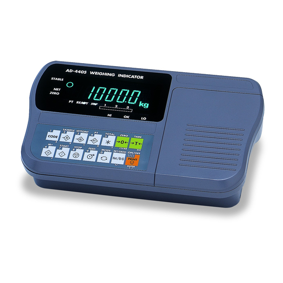
2. 2. 2. 2. Introduction Intro duction Intro Intro duction duction The AD-4405 is a weighing indicator that amplifies signals from a load cell, converts it to digital data and displays it as a mass value. This indicator has the following performance: Input sensitivity: ...... -
Page 7: Installation And Precautions
3. 3. 3. 3. Installation and Precautions Installation and Precautions Installation and Precautions Installation and Precautions 3.1.1. Installation and Precautions The AD-4405 weighing indicator is a precision electronic instrument. Handle the indicator carefully. The operating temperature is -10°C to +40°C (14°F to 104°F). Do not install the scale in direct sunlight. -
Page 8: Adjustment Of The Load Cell Output
3.1.3. Adjustment of the Load Cell Output Caution Use a metal film resistor in the range of 50kohm to 500kohm with a good temperature coefficient, when adding a resistor to adjust a load cell output. Use as large of a resistance value as possible in the range in which the zero adjustment is possible. -
Page 9: Installing An Option Board
3.1.5. Installing an Option Board This is the procedure for the data output board (OP-03, OP-05, OP-07 and OP-08). Caution Do not remove any screws without the following step. Step 1 Remove the power cord from the power outlet (mains) and other cables from the indicator. -
Page 10: Description Of Panels And Symbols
4. 4. 4. 4. Description of Panels and symbols Description of Panels and symbols Description of Panels and symbols Description of Panels and symbols 4.1.1. Front Panel Description Name Description STABLE Indicates when the display is stable. Indicates when the display is the net weight. ZERO Indicates when the display weight is in the Zero range. -
Page 11: Rear Panel Description
ZERO key The key to zero the current display. CLEAR key The key to clear the setting value. TARE key The key to perform tare. The key to proceed to the next step without changing the ESC key parameter set. NET/GROSS key The key to select net or gross weight in the display. -
Page 12: Accessories And Options
4.1.4. Accessories and options Standard accessories Standard accessories Standard accessories Standard accessories Instruction manual Load cell plug JM-NJC-207-PF 0.2A or 0.315A time lag fuse FS-EAWK-200MA Accessories FS-EAWK-315MA Capacity label Function seal Caution Please confirm that the receptacle type and local voltage is correct for your indicator (scale). -
Page 13: Calibration
5. 5. 5. 5. Calibration Calibration Calibration Calibration This indicator, converts an input voltage from a load cell to the "mass" value, and displays it. Calibration is the adjustment function so that the scale (indicator) can display the weight correctly. 5.1.1. -
Page 14: Calibration Procedure
Note that the key does not function alone. Press the key while ON/OFF holding the key to end the calibration mode, if mis-operation. After ON/OFF displaying Can5el, press the key to end the calibration mode and ON/OFF turn the indicator off. When displaying Caloff , press the +/- key while pressing the NOTE: key,... - Page 15 Dual Range <First range> Select the resolution, decimal point position and format. ¯ <First range> Select the weighing range ¯ <Second range> Select the resolution ¯ <Second Range> Specify the weighing capacity For the range function, refer to “5.3. Weighing Range Function”. Specifying Specifying the Range and Unit the Range and Unit...
-
Page 16: To Get Stabilized Data
Specifyi Specifyi Specifyi Specifying ng the Weighing Range of the First Range the Weighing Range of the First Range the Weighing Range of the First Range the Weighing Range of the First Range Step 3 After displaying Cap for 2 seconds, the first range or the weighing capacity of single range will be displayed. -
Page 17: Zero Calibration
5.2.3. Zero Calibration Zero calibration Procedure Cal 0 Step 8 Check the display. Select a zero calibration method to adjust the zero point The adjustment method Weighing input with nothing on the To step 9 (Normal way) weighing unit. The numerical way to Digital input enter a load cell output To step 10... -
Page 18: Exiting The Calibration Mode
Weighing a Mass less than the Maximum Capacity Step12 Set a mass value using the keys. Span calibration Step13 Place a mass equivalent to the displayed value Maximum capacity on the weighing unit. Proceed to step 15. To step 14, step 16 To step 12 Weighing a Maximum Capacity Mass Step14 Place a mass equivalent to the maximum... -
Page 19: Weighing Range Function
Cal 0 key ..The key to store the parameters temporarily. Proceed to the display. Press and hold the key and press the ON/OFF No parameters are changed, CanCel is displayed and the calibration mode is finished. Step18 Press the key to turn the display off. -
Page 20: Setting The Division And Range
5.3.1. Setting the Division and Range Consider the following rules to design the weighing range. Rule 1 Select the division and range of each weighing range so as to fit the following inequality. The first range < the second range The division of the next weighing range is automatically set larger than the division of the lower weighing range. -
Page 21: Gravity Compensation Function
5.5. 5.5. 5.5. 5.5. Gravity Compensation Function Gravity Compensation Function Gravity Compensation Function Gravity Compensation Function If the scale is used at the calibration location, it is not necessary to perform this function. If there is a difference of gravity acceleration between the installed location and calibration location it may cause a weighing error. -
Page 22: The Gravity Acceleration Table
5.5.1. The Gravity Acceleration Table Amsterdam 9.813 m/s Manila 9.784 m/s Athens 9.800 m/s Melbourne 9.800 m/s Auckland NZ 9.799 m/s Mexico City 9.779 m/s Bangkok 9.783 m/s Milan 9.806 m/s Birmingham 9.813 m/s New York 9.802 m/s Brussels 9.811 m/s Oslo 9.819 m/s Buenos Aires... -
Page 23: 5.6. Calibration Error Code List
5.6. Calibration Error Cod 5.6. Calibration Error Code List e List 5.6. 5.6. Calibration Error Cod Calibration Error Cod e List e List Exiting from a Calibration error key..The key to return to the point where an error occurred. Retry the operation. key while pressing the key. -
Page 24: Functions
6. 6. 6. 6. Functions Functions Functions Functions There are two parameters lists, one for the F-functions and one for the CF-functions. These functions control the indicator. The parameters of each function are stored in non-volatile memory, and are not lost even if power is turned off or cut off. F-functions: These parameters can always be changed and are used for internal settings. -
Page 25: 6.2. F-Functions
6.2. F F F F - - - - Functions 6.2. Functions 6.2. 6.2. Functions Functions Weighing Conditions (Digital Filter, Zero trucking and Stability) Parameter Item Description 2 d/ 1.6s 4 d/ 1.6s 8 d/ 1.6s 16 d/ 1.6s 32 d/ 1.6s 64 d/ 1.6s If weak filter is set, the response Filter... - Page 26 Display and Other General Functions Parameter Item Description 5 times/s The selection in the unstable Display update rate condition. 10 times/s Left: Item, select using the Key click ZERO (Sound or no) Right: Parameter, select using the LoLo / Zero band keys [Type2] 0: no sound,...
- Page 27 External Input Parameter Item Description Not used (No function) ** 0 ZERO key TARE key NET/GROSS key ON/OFF key PRINT key, ENTER key FEED key Serial data output (Format 1) Serial data output (Format 2) Accumulation (M+) EXT1 Start batching Function selection of Stop batching external input...
- Page 28 Comparator Parameter Item Description Not used Upper/lower limit comparison (2 Limits setting) Upper/lower limit comparison (Target and allowance) Upper/lower limit comparison (Target and % allowance) HH/Hi/OK/Lo/LL comparison (4 Limits setting) HH/Hi/OK/Lo/LL comparison (Target and allowance) HH/Hi/OK/Lo/LL comparison (Target and % allowance) Comparator function Check weighing 1 Check weighing 2...
- Page 29 Data Output Parameter Item Description ** 0 No data output Set f31, 32, 33 Analog output Data output Serial output RS-232C, RS-422/485 Serial output (Zero suppressing) Initial settings. Analog Output Parameter Item Description Displayed data Gross data Output data Net data Polarity is -999999 to 999999 (Initial setting is 0) Weight value at 4mA output...
- Page 30 Current Loop Output Parameter Item Description ** 0 Displayed data Gross data Net data Output data Tare data Gross data / Net data / Tare data Stream mode Manual mode Auto print mode(+) Output mode Auto print mode(+/-) When accumulation, automatically output ** 5 Not output ** 0...
- Page 31 Serial Interface Parameter Item Description ** 0 Stream mode, command is not acceptable Manual mode, command is effective Auto print mode(+), command is effective Output mode Auto print mode(+/-), command is effective When accumulation, automatically output Command mode (output by command only) No output ** 1 Manual, Fixed format...
- Page 32 Calendar / Clock Function Parameter Item Description 12hrs. display (00 to 11, AM / PM) Time display 24hrs. display (00 to 23) YY/MM/DD MM/DD/YY Date format DD/MM/YY 00 to (Display/output year) – 2 digits Difference between Initial setting is 0. (Christian year) Christian year 4digits(Numeric)
- Page 33 Print Format Parameter Description Item No print 0 0 : Line feed only Device number ID# The number decided F06 Code number CD:x Data number No.xxxxx Judged result HH/H /OK/L /LL (2 digits) YMD order decided f51 Date 11/11/11 Time hh:mm:ss (AM or PM) [Type3] Accumulated value 07,17,27,57 only...
-
Page 34: Cf-Functions
6.3. CF 6.3. CF- - - - Functions Functions 6.3. 6.3. Functions Functions Parameter Item Description Cf00 No limitation Zero tracking width, motion detection Use limitation at F01, F02, F03, F27 and F28. condition 2% of CAP, Tare limit is 100 % CAP Cf01 Zero range 10% of CAP, Tare limit is 100 % CAP... -
Page 35: Tare
7. 7. 7. 7. Tare Tare Tare Tare The function is used to display a net value with the container weight subtracted from the total weight, if you place an object into a container to weigh it. Using a serial interface such as the RS-232C, you can do this from the external equipment. -
Page 36: Accumulation
8. 8. 8. 8. Accumulation Accumulation Accumulation Accumulation This function accumulates weighing data and stores the total data and the accumulation count. The data is stored in non-volatile memory, and is not lost even if the power is turned off. 8.1.1. -
Page 37: Display And Operation
8.1.2. Display and Operation Action of Accumulating Data When accumulating data, the display blinks once. If the accumulated data is stored, the M+ mark is displayed. Caution This function can not accumulate data with a different unit. Specify a unit before use. - Page 38 Output of Accumulated Data Accumulated data can be output to the serial interface. Output by manual or automatic, and output data format is selected at f41 of the F-function setting. Parameter Manual/Automatic Format No output Manual Fixed format Accumulated data Automatic output at Manual...
-
Page 39: Code Memory
9. 9. 9. 9. Code Memory Code Memory Code Memory Code Memory This indicator has four Code memories (1 through 4). Each Code memory stores a set of setpoints, preset tare and the unit weight for piece counting. The data is stored in non-volatile memory, and is not lost even if the AC power supply is disconnected or cut off. -
Page 40: Comparison
Changing the Code Memory Number by External Input The code memory number can be changed by external input from OP-05 or OP-08. Set f14 and f15 to 18. (OP-08 has only one input; set f15) f13 18 : Inhibit reading EXT.2 and EXT.3 to prevent unintentional reading when switching the codes. -
Page 41: Condition Formula For Comparison
There are 3 type of setting values for each comparison. (1) Set the limit value (upper and lower limit / HiHI, Hi, Lo, LoLo limit). (2) Set the Target value and an acceptable tolerance (upper and lower) in weight. The limit value is calculated automatically. (3) Set the Target value and an acceptable tolerance (upper and lower) in percentage of the target weight. -
Page 42: Setting The Upper/Lower Limit Values
10.1.2. Setting the Upper/Lower Limit Values Step 1 By pressing the key, the selected code memory number is displayed SETPOINT and the first comparison class term (ex. Hi, TG etc.) is blinking. Step 2 Select the comparison class using the following keys: key ..The key to select a comparison class. -
Page 43: Setpoint Comparison
10.2. 10.2. Setpoint Comparison Setpoint Comparison 10.2. 10.2. Setpoint Comparison Setpoint Comparison This function includes the weighing sequence and is used for acquiring a preset target weight. There are four parameters of "Final", "Preliminary", "Free fall" and "Zero band" that use the setpoint comparison. The result of the sequence is output to the three relays of OP-03, Op-05 or OP-08. -
Page 44: Simple Batch
F22 = 9 (Check weighing 3:Loss in weight) F22 = 9 (Check weighing 3:Loss in weight) F22 = 9 (Check weighing 3:Loss in weight) F22 = 9 (Check weighing 3:Loss in weight) Preset target weight Tared Zero Weighing value Final Tare Weighing Free fall... -
Page 45: Setting The Parameters Of Setpoint Comparison
Toward the Zero band Toward the Zero band Toward the Zero band Toward the Zero band Preliminary and Free fall output are holding the off state. Over/Under comparison starts. If f23 30, judgment starts when Free fall turns on. The judgment is not latched and the output is according to the state at the time. The Weighing completion relay is turned on if f24 2. -
Page 46: 11. Hold Function
11. Hold Function Hold Function Hold Function Hold Function This function displays the hold weight data after averaging the weight data for a specific period. Useful to determine a living animal’s weight. Averaging time can be set up to 9.9 seconds by a 0.1 second step. 3 methods are available to start averaging;... - Page 47 f28 determines the averaging time by 0.1second step. f28 0 holds the data at averaging start. The key switch function as the HOLD key (Average start or release holding data) is by pressing the key while pressing the key. TOTAL ENTER The external input function of averaging start is 19 and hold release is 20 of f13, f14 and f15.
-
Page 48: Counting Function
12. Counting Func Counting Function tion Counting Func Counting Func tion tion This function determines the number of objects in a sample based on the unit weight. The unit weight is stored in one of the code memory data in non-volatile memory, and is not lost even if the AC power supply is disconnected. - Page 49 key....The key to register the unit weight and return to the piece ENTER count display. The unit weight is calculated automatically with the weight and the number of samples. Press the key while pressing The key to return to the piece count display without changing the unit weight.
-
Page 50: Calendar / Clock
13. Calendar / Clock Calendar / Clock Calendar / Clock Calendar / Clock The AD-4405 has a built-in calendar/clock backed up by a lithium battery. The calendar/clock continues to operate with AC power turned off. Leap years are automatically corrected. The time and date can be added to the data output and optional built-in printer output. -
Page 51: Setting Time And Date
f53 2 Add 2 digit alphabetical characters including space or dot. There are 3 types, a character and a space, a character and a dot, and one space and a character. Setting specifies 2 digit numbers from the next table. If the set number is excluded from the table at f54, two spaces are output. - Page 52 Step 3 After displaying the date format for 2 seconds, the present date is displayed in f51 format. The f52 parameters are effective in the setting mode. Set the date using the following keys. key..The key to set the value at the blinking digit, then the blinking digit shifts to the right.
-
Page 53: Internal Printer (Op-06)
14. Internal Printer (OP Internal Printer (OP- - - - 06) Internal Printer (OP Internal Printer (OP A dot matrix type printer (OP-06) can be installed in the AD-4405. It can print out the result of weighing, accumulated weight, date and time, etc. The print format can be arranged by the F-Function settings or by using the serial interface command. - Page 54 Installing the Printer Paper (Special roll paper) Step 1 Open the cover. Step 2 Cut the paper end for easy insertion. Step 3 Install the paper end and press the FEED key at the same time. (Paper Feed) Step 4 Arrange the ribbon using the dial. Step 5 Pass the paper end through the cover and close the cover.
-
Page 55: Common Printer And Data Output Items
15. Common Printer and Data Output Common Printer and Data Output Items Items Common Printer and Data Output Common Printer and Data Output Items Items There are some similar functions and operations for the internal printer and the serial data output (RS-232C, RS-422/485 and the current loop). Data output / print output mode Data number (not available the current loop) Interval data output or print out... -
Page 56: Data Number
Description of "Command Mode" (For Serial Interface) f40 5 Function Operation The serial data can be output by the serial interface command only. Data conflicts or accidental data output by mis-operation can be avoided when using multiple instruments with the RS-422/485 interface. Description of "Delay for continual data"... -
Page 57: Setting The Interval Time
15.3.1. Setting the Interval Time key, intval Step 1 By pressing the key while pressing the will SETPOINT(3) PRINT be displayed for 2 seconds. Step 2 Select which interval time to set using the following keys. The item is displayed. key .. -
Page 58: 16. Rs-232C Interface
16. RS RS- - - - 232C Interface 232C Interface 232C Interface 232C Interface 16.1. 16.1. Specification Specifications s s s 16.1. 16.1. Specification Specification Transmission Asynchronous, bi-directional, half-duplex Baud rate 600, 1200, 2400, 4800, 9600 bps Data bits 7 bits, 8 bits Parity bits 1 bit, Even or Odd (for 7data bits) or Non parity (for 8 data bits) Start bit... -
Page 59: Data Format
16.2. 16.2. Data Format Data Format 16.2. 16.2. Data Format Data Format There are two data format types set at F-Function f34 and f35. The initial data format of f34 is shown below. Space code(20h) Carriage return(0Dh) 8 digit data Terminators Line feed(0Ah) Unit... -
Page 60: Command Format
16.3. 16.3. 16.3. 16.3. Command Format Command Format Command Format Command Format Explanation of Command Explanation of Command Explanation of Command Explanation of Commands s s s When performing a command, the received command or replay data is sent back. When the received command can not be performed such as the "busy"... -
Page 61: Commands To Request Data
16.3.1. Commands to Request Data Request Request Request Request for the for the for the for the Display Data (1) Display Data (1) Display Data (1) Display Data (1) When receiving this command, the display data is returned immediately. Template Command Reply Request... -
Page 62: Commands To Control The Indicator
16.3.2. Commands to Control the Indicator Zero Zero Zero Zero the the Display Display Display Display Sets the current display to the zero point. Template Command Reply Tare Tare Tare Tare Sets the current display to zero of the net data. Template Command Reply... - Page 63 Changing the Weight Unit Changing the Weight Unit Changing the Weight Unit Changing the Weight Unit Changes the weight unit. Template Command Reply Changing the Code Memory Changing the Code Memory Changing the Code Memory Changing the Code Memory Changes the Code Memory number. Template SC,m m: code memory number, 0 - 4...
-
Page 64: Commands To Set Parameters
16.3.3. Commands to Set Parameters Set the the Limit/Setpoint Value Limit/Setpoint Value Limit/Setpoint Value Limit/Setpoint Value Sets the limit or setpoint value of the comparison. The decimal point is not necessary. Template Sm,n, [ value ] m: code memory number, 0 - 4 n : setpoint order number, refer to "Setting the setpoint"... -
Page 65: Commands For The Hold Function
16.3.4. Commands for the Hold Function Start Averaging to Hold Start Averaging to Hold Start Averaging to Hold Start Averaging to Hold Starts averaging to hold. The reply differs with the conditions. Template Command Reply Averaging start Averaging now Held Release the Hold Data Release the Hold Data Release the Hold Data... -
Page 66: Ufc Commands
16.4. 16.4. UFC Command UFC Commands s s s 16.4. 16.4. UFC Command UFC Command UFC (Universal Flexi Coms) function enables editing the serial data output format or the print out format freely using the serial interface command. For customizing the print out of the printer or efficient data collection. Output data is not only the indicator’s data/status but also characters at will. - Page 67 Inserting a DeLay time (0.1 second step) Example: DL10 : 1.0 second delay Strings Output or print specified strings enclosed by a single quotation (’). ’ itself is described using three single quotations; ’’’. Example: ’A & D’ ’This is a sample of ’’’ .’ Set data bit = 8 bit if using the 8 bit characters.
-
Page 68: Rs-422/Rs-485, Relay Output(Op-03)
17. RS RS- - - - 422/RS 422/RS- - - - 485, Relay Output(OP 485, Relay Output(OP- - - - 03 03) ) ) ) 422/RS 422/RS 485, Relay Output(OP 485, Relay Output(OP Replacing the RS-232C interface with this option, the RS-422/RS-485 interface can connect up to 32 indicators and control them from a computer or a PLC. - Page 69 Switching Between RS Switching Between RS Switching Between RS Switching Between RS- - - - 422/RS 422/RS 422/RS- - - - 485 422/RS Switching between RS-422/RS-485 is made with the slide switch (S1) on the OP-03 board. Connection Connection Connection Connection The polarity of signals A and B may vary with different computers.
-
Page 70: Relay Output & Control Input (Op-05)
18. Relay Output & Control Input (O Relay Output & Control Input (OP P P P - - - - 05) Relay Output & Control Input (O Relay Output & Control Input (O Replacing the RS-232C interface with this option, 3-relay outputs and 3-control inputs can be used with the RS-232C interface of this option. -
Page 71: 20Ma Analog Output (Op-07)
19. 4 4 4 4 - - - - 20mA Analog Output (OP 20mA Analog Output (OP- - - - 07) 20mA Analog Output (OP 20mA Analog Output (OP The OP-07 analog output option is for sending the weight data to an analog input unit. The output is a 4mA to 20mA current output proportional to the display reading. -
Page 72: Current Loop Output (Op-08)
20. Current Loop Output (OP Current Loop Output (OP- - - - 08) Current Loop Output (OP Current Loop Output (OP Replacing the RS-232C interface with this option, current loop output, 3-relay outputs and 1-control input can be used with the RS-232C interface of this option. RS-232C functions and pin connections are the same as the RS-232C interface described in “16. - Page 73 Current Lo Current Loop Output op Output Current Lo Current Lo op Output op Output The current loop output can be used to output data to an A&D printer and a display unit. The current loop output is of the passive type and requires an external current source of 20 mA current.
-
Page 74: Specifications
21. Specifications Specifications Specifications Specifications Analog Input and A/D Conversion Analog Input and A/D Conversion Analog Input and A/D Conversion Analog Input and A/D Conversion Up to 0.25 mV/division Input sensitivity Input signal range -1 mV ~ 15 mV Load cell excitation voltage 5V DC 5%, 60 mA with sense voltage input Maximum 4 x 350 W load cells Load cell drive capacity... -
Page 75: Dimensions
General General General General Selection by internal connector from 100V AC, 120V AC, Power supply 200V AC and 230V AC, +10% to -15%, 45Hz to 65Hz Power consumption Approximately 20VA Operation temperature -10°C to +40°C (14°F to 104°F) Operation humidity 85% R.H. - Page 76 MEMO Page 74 AD-4405 Weighing Indicator...
- Page 77 MEMO Page 75 AD-4405 Weighing Indicator...
- Page 78 MEMO Page 76 AD-4405 Weighing Indicator...