
Related Manuals for Intel S5000XVNSATA


Summary of Contents for Intel S5000XVNSATA
- Page 1 Intel Workstation Board S5000XVN ® Technical Product Specification Intel order number: D66403-006 Revision 1.5 August 2010 Enterprise Platforms and Services Division – Marketing...
-
Page 2: Revision History
Intel products are not intended for use in medical, life saving, or life sustaining applications. Intel may make changes to specifications and product descriptions at any time, without notice. -
Page 3: Table Of Contents
Intel® Workstation Board S5000XVN TPS Table of Contents Table of Contents 1. Introduction .......................... 1 Chapter Outline......................1 Server Board Use Disclaimer .................. 1 2. Overview ..........................2 Workstation Board Feature Set ................2 Workstation Board Layout ..................3 2.2.1 Workstation Board Connector and Component Layout ........... - Page 4 Table of Contents Intel® Workstation Board S5000XVN TPS 5. Connector/Header Locations and Pin-outs..............35 Board Connector Information................. 35 Power Connectors ....................36 System Management Headers ................37 5.3.1 LCP/AUX IPMB Header ..................37 5.3.2 IPMB Header ......................38 5.3.3 HSBP Header ......................38 5.3.4...
- Page 5 Intel® Workstation Board S5000XVN TPS Table of Contents Workstation Board Power Requirements............... 57 8.3.1 Processor Power Support..................59 Power Supply Output Requirements ..............59 8.4.1 Grounding ......................60 8.4.2 Standby Outputs ....................60 8.4.3 Remote Sense ....................... 60 8.4.4 Voltage Regulation ....................60 8.4.5...
- Page 6 List of Figures Intel® Workstation Board S5000XVN TPS List of Figures Figure 1. Workstation Board Photograph..................3 Figure 2. Major Board Components....................5 Figure 3. Mounting Hole Positions ....................6 Figure 4. Component Positions..................... 7 Figure 5. Restricted Areas on Side 1 .................... 8 Figure 6.
- Page 7 Intel® Workstation Board S5000XVN TPS List of Tables List of Tables Table 1. Workstation Board Features ................... 2 Table 2. Processor Support Matrix ..................... 14 Table 3. I C Addresses for Memory Module SMB ..............17 Table 4. Maximum Eight-DIMM System Memory Configruation – x8 Single Rank ..... 18 Table 5.
- Page 8 List of Tables Intel® Workstation Board S5000XVN TPS Table 33. SSI 6-pin Fan Header Pin-out (J3H1, J3H2, J3H3, and J3H4)........44 Table 34. Server Board Jumpers (J1C3, J1D1, J1D2, and J1E3) ..........46 Table 35. System Status LED..................... 52 Table 36. Workstation Board Design Specifications ..............56 ®...
- Page 9 Intel® Workstation Board S5000XVN TPS List of Tables <This page is intentionally left blank.> Revision 1.5 Intel order number: D66403-006...
-
Page 10: Introduction
It is the responsibility of the system integrator who chooses not to use Intel- developed server building blocks to consult vendor datasheets and operating parameters to determine the amount of air flow required for their specific application and environmental conditions. -
Page 11: Overview
Feature Description ® ® Processors Socket J (771-pin LGA sockets) supporting one or two Intel Xeon processors 5000 sequence, with system bus speeds of 667 MHz, 1066 MHz, and 1333 MHz. Memory Eight DIMM sockets supporting fully buffered DIMM technology (FBDIMM) memory. -
Page 12: Workstation Board Layout
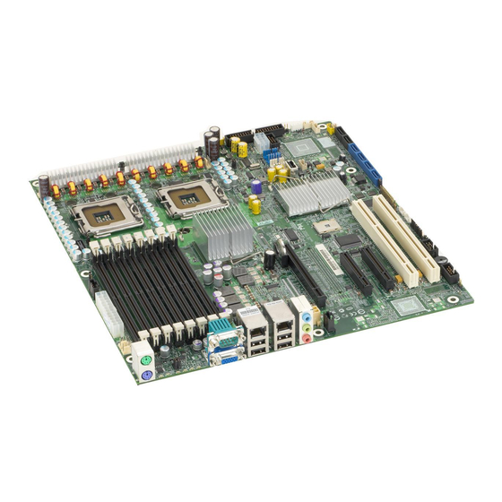
Intel® Workstation Board S5000XVN TPS Overview Feature Description Fans Support for Two processor fans Four front hot-swap fans Two rear system fans ® Server Management Support for Intel System Management Software Workstation Board Layout Figure 1. Workstation Board Photograph Revision 1.5... -
Page 13: Workstation Board Connector And Component Layout
Overview Intel® Workstation Board S5000XVN TPS 2.2.1 Workstation Board Connector and Component Layout The following figure shows the board layout of the workstation board. Each connector and major component is identified by a letter. A component descriptions table follows the figure. -
Page 14: Figure 2. Major Board Components
Intel® Workstation Board S5000XVN TPS Overview H. P12V4 connector W. System fan 2 header LL. SATA 5 or SAS 3 (SAS 3 on order code S5000XVNSASR only) I. Back panel I/O ports X. System fan 1 header MM. USB port J. -
Page 15: Workstation Board Mechanical Drawings
Overview Intel® Workstation Board S5000XVN TPS 2.2.2 Workstation Board Mechanical Drawings Figure 3. Mounting Hole Positions Revision 1.5 Intel order number: D66403-006... -
Page 16: Figure 4. Component Positions
Intel® Workstation Board S5000XVN TPS Overview Figure 4. Component Positions Revision 1.5 Intel order number: D66403-006... -
Page 17: Figure 5. Restricted Areas On Side 1
Overview Intel® Workstation Board S5000XVN TPS 304.80 12.000 11.20 0.441 HEATSINK DISSASEMBLY AREA, 116.000 60.100 .275" [8.26mm] MAX COMPONENT 4.5669 2.3661 HEIGHT RESTRICTION, 4 PLACES 18.72 20.32 0.737 0.800 IMM3 COMPONENT HEIGHT 3.6 MM Ø 10.160 0.4000 GROUND PAD BOTH SIDES... -
Page 18: Figure 6. Restricted Areas On Side 2
Intel® Workstation Board S5000XVN TPS Overview LIMITED COMPONENT HEIGHT 2X 3.120 .058" MAXIMUM 13 PLACES 0.1228 78.74 3.100 7.620 20.320 0.3000 0.8000 SEE DETAIL B 20.320 0.8000 2X 8.000 25.40 11 PLCS 2X 0.350 0.3150 1.000 0.0138 NO COMPONENTS ALLOWED 66.554... -
Page 19: Figure 7. Restricted Areas On Side 2, "Detail B
Overview Intel® Workstation Board S5000XVN TPS 5.00 5.00 0.197 0.197 3X 4.00 0.157 3X 3.00 0.118 3X 10.13 0.399 CHASSIS ID PADS Figure 7. Restricted Areas on Side 2, “Detail B” Revision 1.5 Intel order number: D66403-006... -
Page 20: Figure 8. Cpu And Memory Duct Keepout
Intel® Workstation Board S5000XVN TPS Overview 10.160 [0.4000] 0.000 [0.0000] 14.0mm COMPONENT HEIGHT LIMIT DEFINED BY DUCT DETAIL 26.635 26.578 [1.0464] [1.0486] 16.5mm COMPONENT HEIGHT 43.302 [1.7048] LIMIT DEFINE BY DUCT DETAIL SUPPORT AREA, NO COMPONENT ALLOWED 73.482 14.0mm COMPONENT HEIGHT [2.8930]... -
Page 21: Workstation Board Atx I/O Layout
Overview Intel® Workstation Board S5000XVN TPS 2.2.3 Workstation Board ATX I/O Layout The following drawing shows the layout of the rear I/O components for the workstation board: AF001037 A. PS/2 mouse F. Audio out B. Serial A port G. Microphone C. -
Page 22: Functional Architecture
The architecture and design of the Intel Workstation Board S5000XVN is based on the Intel ® ® S5000X chipset. This chipset is designed for systems that use the Intel Xeon processor with system bus speeds of 667 MHz, 1066 MHz, and 1333 MHz. -
Page 23: Intel ® 5000X Memory Controller Hub (Mch)
This section provides a high-level overview of some of these core functions as they pertain to this workstation board. You can obtain additional information from the Intel S5000 Server Board Family Datasheet and the Intel 5000 Series Chipset Memory Controller Hub Datasheet. - Page 24 CEK spring, workstation board, TIM, and heatsink. The CEK spring is removable, which allows for the use of non-Intel heatsink retention solutions. Note: The processor heatsink and CEK spring shown in the following diagram are for reference purposes only.
-
Page 25: Memory Subsystem
Functional Architecture Intel® Workstation Board S5000XVN TPS Figure 11. CEK Processor Mounting 3.1.3 Memory Subsystem The MCH supports four fully buffered DIMM (FBD) memory channels. FBD memory uses a narrow, high–speed, frame-oriented interface referred to as a channel. The four FBD channels are organized into two branches of two channels per branch. -
Page 26: Figure 12. Memory Layout
Intel® Workstation Board S5000XVN TPS Functional Architecture Channel B Channel C Channel A Channel D Branch 0 Branch 1 TP02299 Figure 12. Memory Layout To boot the system, the system BIOS on the workstation board uses a dedicated I C bus to retrieve DIMM information needed to program the MCH memory registers. -
Page 27: Table 4. Maximum Eight-Dimm System Memory Configruation - X8 Single Rank
Memory error detection and correction Memory scrubbing Retry on correctable errors Memory built-in self-test DIMM sparing Memory mirroring For more information about these features, refer to the Intel ® S5000 Server Board Family Datasheet. 3.1.3.2 Supported Memory The workstation board supports up to eight DDR2-533 or DDR2-667 fully-buffered DIMMs (FBD memory). - Page 28 Intel® Workstation Board S5000XVN TPS Functional Architecture Note: This workstation board supports only fully buffered DDR2 DIMMs (FBDIMMs. See the ® Intel Workstation Board S5000XVN Tested Memory List for a list of supported memory for this server board. 3.1.3.3 DIMM Population Rules and Supported DIMM Configurations DIMM population rules depend on the operating mode of the memory controller, which is determined by the number of DIMMs installed.
-
Page 29: Table 7. Dimm Population Rules
The supported memory configurations must meet population rules defined above. For best performance, you should install a minimum of four DIMMs across memory branches. ® Although mixed DIMM capacities between channels are supported, Intel does not validate FBDIMMs in mixed DIMM configurations. Revision 1.5... -
Page 30: Figure 13. Minimum 2-Dimm Memory Configuration
Branch 1 TP02300 Figure 13. Minimum 2-DIMM Memory Configuration Note: The workstation board supports single DIMM mode operation. Intel will only validate and support this configuration with a single 512 MB x8 FBDIMM installed in DIMM socket A1. 3.1.3.4 Non-mirrored Mode Memory Upgrades The minimum memory upgrade increment is two DIMMs per branch. -
Page 31: Figure 14. Recommended Four Dimm Configuration
Fuctional Architecture Intel® Workstation Board S5000XVN TPS Channel B Channel C Channel A Channel D Branch 0 Branch 1 TP02301 Figure 14. Recommended Four DIMM Configuration Functionally, DIMM sockets A2 and B2 could have been populated instead of DIMM sockets C1 and D1. -
Page 32: Figure 15. Single Branch Mode Sparing Dimm Configuration
Intel® Workstation Board S5000XVN TPS Functional Architecture 3.1.3.4.2.1 Single Branch Mode Sparing Slot 2 DIMM_A2 DIMM_B2 DIMM_C2 DIMM_D2 Slot 1 DIMM_A1 DIMM_B1 DIMM_C1 DIMM_D1 Channel A Channel B Channel C Channel D Branch 0 Branch 1 Intel® 5000X Memory Controller Hub Figure 15. -
Page 33: Snoop Filter
Power management System RTC General purpose I/O This section describes the function of most of the listed features as they pertain to this workstation board. For more detailed information, see the Intel 631xESB/632xESB I/O Controller Hub Datasheet. 3.2.1 PCI Subsystem The primary I/O buses for the server board are PCI, PCI Express*, and PCI-X* with six independent PCI bus segments. -
Page 34: Table 8. Pci Bus Segment Characteristics
Intel® Workstation Board S5000XVN TPS Functional Architecture Table 8. PCI Bus Segment Characteristics PCI Bus Segment Voltage Width Speed Type PCI I/O Card Slots PCI32 3.3 V 32 bit 33 MHz None ESB2-E 3.3 V/5.0 V 64 bit 100 MHz... -
Page 35: Serial Ata Support
Embedded Server RAID Technology II Support ® ® The onboard storage capability of this workstation board includes support for Intel Embedded Server RAID Technology II, which provides three standard software RAID levels: data stripping (RAID Level 0), data mirroring (RAID Level 1), and data stripping with mirroring (RAID Level 10). -
Page 36: Parallel Ata (Pata) Support
Embedded Server RAID Technology implementation and ® provides the ability for an Intel Embedded Server RAID Technology volume to be used as a ® boot disk and detect any faults in the Intel Embedded Server RAID Technology volume(s) ® attached to the Intel RAID controller. -
Page 37: Audio Codec
Intel® Workstation Board S5000XVN TPS Audio Codec ® The workstation board supports the Intel High Definition audio subsystem based on the Realtek* ALC260 audio codec. The ALC260 is a 2-channel HD Audio codec featuring a 24-bit, 2-channel DAC and two stereo 20-bit ADCs. -
Page 38: Sas Controller
Intel® Workstation Board S5000XVN TPS Functional Architecture The workstation board supports the following audio connections through the rear I/O: LINE OUT LINE IN MIC IN Figure 17. Rear I/O Panel Audio Connector The workstation board supports ATAPI CD-ROM (a 1x4-pin ATAPI-style connector for connecting an internal ATAPI CD-ROM drive to the audio mixer, connector J4A1) audio connection inside the chassis. -
Page 39: I/Oat)
Functional Architecture Intel® Workstation Board S5000XVN TPS The 82563EB device is based upon proven PHY technology integrated into Intel’s gigabit Ethernet controllers. The physical layer circuitry provides a standard IEEE 802.3 Ethernet interface for 1000BASE-T, 100BASE-TX, and 10BASE-T applications (802.3, 802.3u, and 802.3ab). -
Page 40: 3.6 Super I/O
Intel® Workstation Board S5000XVN TPS Functional Architecture 3.6 Super I/O Legacy I/O support is provided by using a National Semiconductor* PC87427 Super I/O device. This chip contains all of the necessary circuitry to support the following functions: GPIOs Two serial ports... -
Page 41: System Health Support
Functional Architecture Intel® Workstation Board S5000XVN TPS 3.6.5 System Health Support The super I/O provides an interface via GPIOs for BIOS and system management firmware to activate the diagnostic LEDs, the FRU fault indicator LEDs for processors, FBDIMMS, fans, and the system status LED. -
Page 42: Platform Management
Server Management Bus (SMBUS) architecture used on this workstation board. See Appendix B for onboard sensor data. ® For more detailed platform management information, see the Intel S5000 Server Board Family Datasheet. Revision 1.5... -
Page 43: Figure 18. Smbus Block Diagram
Platform Management Intel® Workstation Board S5000XVN TPS Figure 18. SMBUS Block Diagram Revision 1.5 Intel order number: D66403-006... -
Page 44: Connector/Header Locations And Pin-Outs
Intel® Workstation Board S5000XVN TPS Connector/Header Locations and Pin-outs Connector/Header Locations and Pin-outs Board Connector Information The following section provides detailed information regarding all connectors, headers and jumpers on the workstation board. The following table lists all connector types available on the board and the corresponding reference designators printed on the silkscreen: Table 11. -
Page 45: Power Connectors
Connector/Header Locations and Pin-outs Intel® Workstation Board S5000XVN TPS Connector Quantity Reference Designators Connector Type Pin Count Configuration J1D2 (Password Clear), J1D1 (CMOS Clear), J1C3 Jumper jumpers (BIOS Bank Select), J1E3 (BMC Force Update) Power Connectors The main power supply connection uses an SSI-compliant 2x12 pin connector (J9B5). In... -
Page 46: System Management Headers
Intel® Workstation Board S5000XVN TPS Connector/Header Locations and Pin-outs Table 13. 12-V Power Connector Pin-out (J3J2) Signal Color Black Black Black Black +12 Vdc Yellow/black +12 Vdc Yellow/black +12 Vdc Yellow/black +12 Vdc Yellow/black Table 14. Power Supply Signal Connector Pin-out (J9D1) -
Page 47: Ipmb Header
Connector/Header Locations and Pin-outs Intel® Workstation Board S5000XVN TPS 5.3.2 IPMB Header Table 17. IPMB Header Pin-out (J4J1) Signal Name Description SMB_IPMB_5VSB_DAT BMC IMB 5 V Standby Data Line Ground SMB_IPMB_5VSB_CLK BMC IMB 5 V Standby Clock Line 5.3.3 HSBP Header Table 18. -
Page 48: Front Panel Connector
Front Panel Connector ® The workstation board provides a 24-pin SSI front panel connector (J1E4) for use with Intel third-party chassis. The following table provides the pin-out for this connector: Table 22. Front Panel SSI Standard 24-pin Connector Pin-out (J1E4) -
Page 49: Ide Connector
Connector/Header Locations and Pin-outs Intel® Workstation Board S5000XVN TPS Signal Name NIC_A_MDI1P NIC_A_MDI1N NIC_A_MDI0P NIC_A_MDI0N 11 (D1) NIC_LINKA_1000_N (LED 12 (D2) NIC_LINKA_100_N (LED) 13 (D3) NIC_ACT_LED_N NIC_LINK_LED_N 5.5.2 IDE Connector The workstation board provides one legacy IDE ATA100 40-pin connector (J2J2). The pin-out is defined in the following table: Table 24. -
Page 50: Sata/Sas Connectors
Intel® Workstation Board S5000XVN TPS Connector/Header Locations and Pin-outs 5.5.3 SATA/SAS Connectors The workstation board provides up to six SATA/SAS connectors: SATA-0 (J1J1) SATA-1 (J1H2) SATA-2/SAS-0 (J1H1) SATA-3/SAS-1 (J1G2) SATA-4/SAS-2 (J1G1) SATA-5/SAS-3 (J1F2) The pin configuration for each connector is identical and is defined in the following table: Table 25. -
Page 51: Keyboard And Mouse Connector
Connector/Header Locations and Pin-outs Intel® Workstation Board S5000XVN TPS Table 27. Internal 9-pin Serial B Header Pin-out (J1B1) Signal Name Description SPB_DCD DCD (carrier detect) SPB_DSR DSR (data set ready) SPB_SIN_L RXD (receive data) SPB_RTS RTS (request to send) SPB_SOUT_N... -
Page 52: Cd-In Header
Intel® Workstation Board S5000XVN TPS Connector/Header Locations and Pin-outs Table 29. External USB Connector Pin-out (JA6A1, JA6A2) Signal Name Description USB_OC USB_PWR USB_PN DATAL0 (Differential data line paired with DATAH0) USB_PP DATAH0 (Differential data line paired with DATAL0) Ground One 2x5 connector on the workstation board (J3J1) provides an option to support an additional two USB ports. -
Page 53: Fan Headers
Connector/Header Locations and Pin-outs Intel® Workstation Board S5000XVN TPS Fan Headers The workstation board provides four SSI-compliant 4-pin and four SSI-compliant 6-pin fan headers to be used as CPU, and I/O cooling fans. 3-pin fans are supported on all fan headers. 6-pin fans are supported on headers J3H4, J3H3, J3H2, and J3H1. - Page 54 VLSI and power delivery components that need adequate airflow to cool. Intel’s own chassis are designed and tested to meet the intended thermal requirements of these components when the fully integrated system is used together. It is the responsibility of...
-
Page 55: Jumper Blocks
Jumper Blocks Intel® Workstation Board S5000XVN TPS Jumper Blocks The workstation board has several 3-pin jumper blocks that you can use to configure, protect, or recover specific features of the server board. Pin 1 on each jumper block can be identified by the following symbol on the silkscreen: ▼... -
Page 56: Cmos Clear And Password Reset Usage Procedure
The CMOS Clear (J1D1) and Password Reset (J1D2) recovery features are designed such that the necessary operation can be achieved with minimal system down time. The usage procedure for these two features has changed from previous generation Intel server boards. The following procedure outlines the new usage model. -
Page 57: Bios Select Jumper
To perform a normal BIOS update, perform the following steps: 1. Boot the system with the jumper covering pins 2 and 3. ® 2. Update the BIOS using iFlash or the Intel One Flash Update (OFU) utility. 3. Reset the system. -
Page 58: Intel Light Guided Diagnostics
Intel® Workstation Board S5000XVN TPS Intel® Light Guided Diagnostics Intel Light Guided Diagnostics ® The workstation boards have several onboard diagnostic LEDs to assist in troubleshooting board-level issues. This section provides a description the location and function of each LED on the workstation board. -
Page 59: Fan Fault Leds
Intel® Light Guided Diagnostics Intel® Workstation Board S5000XVN TPS Fan Fault LEDs Fan fault LEDs are present for the two CPU fans and the two rear system fans. The two CPU fan fault LEDs are located next to each CPU fan header. The two rear system fan fault LEDs... -
Page 60: System Id Led And System Status Led
Intel® Workstation Board S5000XVN TPS Intel® Light Guided Diagnostics System ID LED and System Status LED The workstation board provides LEDs for both system ID and system status. These LEDs are located in the rear I/O area of the workstation board between the PS/2* mouse/keyboard stacked connectors and the video/serial stacked connectors. -
Page 61: Table 35. System Status Led
Intel® Light Guided Diagnostics Intel® Workstation Board S5000XVN TPS The bi-color System Status LED operates as follows: Table 35. System Status LED Color State Criticality Description Not ready AC power off Green/ Alternating Not ready Pre DC Power On – 15-20 second BMC Initialization when AC is... -
Page 62: System Status Led - Bmc Initialization
Intel® Workstation Board S5000XVN TPS Intel® Light Guided Diagnostics 7.3.1 System Status LED – BMC Initialization When the AC power is first applied to the system and 5V-STBY is present, the BMC on the server board requires 20-30 seconds to initialize. During this time, the system status LED will blink, alternating between amber and green, and the power button functionality of the control panel is disabled, preventing the server from powering up. -
Page 63: Processor Fault Leds
Intel® Light Guided Diagnostics Intel® Workstation Board S5000XVN TPS Processor Fault LEDs The workstation board provides a fault LED for each processor socket. These LEDs are located near the processor sockets. AF001035 Figure 24. Processor Fault LED Locations Post Code Diagnostic LEDs... -
Page 64: Figure 25. Post Code Diagnostic Led Location
Intel® Workstation Board S5000XVN TPS Intel® Light Guided Diagnostics AF001036 A. Status LED D. Bit 2 LED (POST LED) B. ID LED E. Bit 1 LED (POST LED) C. MSB LED (POST LED) F. LSB LED (POST LED) Figure 25. POST Code Diagnostic LED Location Revision 1.5... -
Page 65: Design And Environmental Specifications
It is the responsibility of the system integrator who chooses not to use Intel developed workstation building blocks to consult vendor datasheets and operating parameters to determine the amount of air flow required for their specific application and environmental conditions. -
Page 66: Board-Level Mtbf
Workstation Board Power Requirements ® This section provides power supply design guidelines for a system using the Intel Workstation Board S5000XVN including voltage and current specifications, and power supply on/off sequencing characteristics. The following diagram shows the power distribution implemented on this workstation boards: Revision 1.5... -
Page 67: Figure 26. Power Distribution Block Diagram
Design and Environmental Specifications Intel® Workstation Board S5000XVN TPS Figure 26. Power Distribution Block Diagram Revision 1.5 Intel order number: D66403-006... -
Page 68: Processor Power Support
Note: These values are for reference only. The Intel Xeon ) processor 5000 sequence Datasheet contains the actual specifications for the processor. If the values found in the Intel(r) ® Xeon processor 5000 sequence Datasheet are different than those published here, the Dual- ®... -
Page 69: Grounding
Design and Environmental Specifications Intel® Workstation Board S5000XVN TPS 8.4.1 Grounding The grounds of the pins of the power supply output connector provide the power return path. The output connector ground pins is connected to safety ground (power supply enclosure). This grounding should is designed to ensure passing the maximum allowed common mode noise levels. -
Page 70: Dynamic Loading
Intel® Workstation Board S5000XVN TPS Design and Environmental Specifications Table 39. Voltage Regulation Limits Parameter Tolerance Minimum Nominal Maximum Units +3.3V - 5%/+5% +3.14 +3.30 +3.46 - 5%/+5% +4.75 +5.00 +5.25 +12V - 5%/+5% +11.40 +12.00 +12.60 +12V - 5%/+5% +11.40... -
Page 71: Ripple/Noise
Design and Environmental Specifications Intel® Workstation Board S5000XVN TPS Table 41. Capacitive Loading Conditions Output Minimum Maximum Units +3.3 V 6800 +5 V 4700 1, 2, 3, 4 +12 V 500 each 11,000 -12 V +5 VSB Note: Maximum continuous total output power should not exceed 670 W. -
Page 72: Timing Requirements
Intel® Workstation Board S5000XVN TPS Design and Environmental Specifications Table 42. Ripple and Noise +3.3 V +5 V +12 V 1, 2, 3, 4 -12 V +5 VSB 50mVp-p 50mVp-p 120mVp-p 120mVp-p 50mVp-p Note: Maximum continuous total output power should not exceed 670 W. -
Page 73: Figure 27. Output Voltage Timing
Design and Environmental Specifications Intel® Workstation Board S5000XVN TPS V out 10% V out T vout_off T vout_rise T vout_on TP02313 Figure 27. Output Voltage Timing Table 44. Turn On/Off Timing Item Description Minimum Maximum Units Delay from AC being applied to 5VSB being within regulation. -
Page 74: Residual Voltage Immunity In Standby Mode
Intel® Workstation Board S5000XVN TPS Design and Environmental Specifications AC Input vout_holdup Vout pwok_low AC_on_delay pwok_off sb_on_delay sb_on_delay pwok_on pwok_off pwok_on PWOK pson_pwok pwok_holdup 5VSB sb_vout 5VSB holdup pson_on_delay PSON AC turn on/off cycle PSON turn on/off cycle Figure 28. Turn On/Off Timing (Power Supply Signals) 8.4.9... -
Page 75: Regulatory And Certification Information
The final configuration of your end system product may require additional EMC compliance testing. For more information please contact your local Intel Representative. This is an FCC Class A device. Integration of it into a Class B chassis does not result in a Class B device. -
Page 76: Certifications/Registrations/Declarations
Intel® Workstation Board S5000XVN TPS Regulatory and Certification Information 9.1.3 Certifications/Registrations/Declarations UL Certification or NRTL (US/Canada) CB Certifications (International) CE Declaration of Conformity (CENELEC Europe) FCC/ICES-003 Class A Attestation (USA/Canada) C-Tick Declaration of Conformity (Australia) MED Declaration of Conformity (New Zealand) -
Page 77: 9.3 Electromagnetic Compatibility Notices
Regulatory and Certification Information Intel® Workstation Board S5000XVN TPS 9.3 Electromagnetic Compatibility Notices 9.3.1 FCC Verification Statement (USA) This device complies with Part 15 of the FCC Rules. Operation is subject to the following two conditions: (1) This device may not cause harmful interference, and (2) this device must accept any interference received, including interference that may cause undesired operation. -
Page 78: Europe (Ce Declaration Of Conformity)
English translation of the notice above: 1. Type of Equipment (Model Name): On License and Product 2. Certification No.: On RRL certificate. Obtain certificate from local Intel representative 3. Name of Certification Recipient: Intel Corporation 4. Date of Manufacturer: Refer to date code on product 5. -
Page 79: 9.4 Restriction Of Hazardous Substances (Rohs) Compliance
Intel® Workstation Board S5000XVN TPS 9.4 Restriction of Hazardous Substances (RoHS) Compliance Intel has a system in place to restrict the use of banned substances in accordance with the European Directive 2002/95/EC. Compliance is based on declaration that materials banned in the RoHS Directive are either (1) below all applicable substance threshold limits or (2) an approved/pending RoHS exemption applies. -
Page 80: Appendix A: Integration And Usage Tips
Intel ® S5000PSL, S5000XSL, S5000XVN, and Server System SC5400RA Tested Hardware and OS List. For a list of Intel supported hard disk drives for this workstation board, see the Intel ® Server Board/Systems Tested Hard Drive List. ®... -
Page 81: Appendix B: Bmc Sensor Tables
Appendix B: BMC Sensor Tables Intel® Workstation Board S5000XVN TPS Appendix B: BMC Sensor Tables This appendix lists the sensor identification numbers and information about the sensor type, name, supported thresholds, assertion and de-assertion information, and a brief description of the sensor purpose. - Page 82 Intel® Workstation Board S5000XVN TPS Appendix B: BMC Sensor Tables Rearm Sensors The rearm is a request for the event status for a sensor to be rechecked and updated upon a transition between good and bad states. Rearming the sensors can be done manually or automatically.
-
Page 83: Table 45. Bmc Sensors
Appendix B: BMC Sensor Tables Intel® Workstation Board S5000XVN TPS Table 45. BMC Sensors Sensor Sensor System Sensor Type Event/Reading Event Offset Criticality Assert/ Readable Event Data Rearm Standby Name Number Applicability Type Triggers De-assert Value/Offsets Power Unit Power Unit... - Page 84 Intel® Workstation Board S5000XVN TPS Appendix B: BMC Sensor Tables Sensor Sensor System Sensor Type Event/Reading Event Offset Criticality Assert/ Readable Event Data Rearm Standby Name Number Applicability Type Triggers De-assert Value/Offsets Platform Platform Sensor Secure mode – Trig Offset...
- Page 85 Appendix B: BMC Sensor Tables Intel® Workstation Board S5000XVN TPS Sensor Sensor System Sensor Type Event/Reading Event Offset Criticality Assert/ Readable Event Data Rearm Standby Name Number Applicability Type Triggers De-assert Value/Offsets BB +3.3V Voltage Threshold [u,l] [c,nc] Threshold As and...
- Page 86 Intel® Workstation Board S5000XVN TPS Appendix B: BMC Sensor Tables Sensor Sensor System Sensor Type Event/Reading Event Offset Criticality Assert/ Readable Event Data Rearm Standby Name Number Applicability Type Triggers De-assert Value/Offsets SYS FAN Chassis- Threshold [l] [c,nc] Threshold As and...
- Page 87 Appendix B: BMC Sensor Tables Intel® Workstation Board S5000XVN TPS Sensor Sensor System Sensor Type Event/Reading Event Offset Criticality Assert/ Readable Event Data Rearm Standby Name Number Applicability Type Triggers De-assert Value/Offsets Fan 8 Chassis- Generic Device present As and –...
- Page 88 Intel® Workstation Board S5000XVN TPS Appendix B: BMC Sensor Tables Sensor Sensor System Sensor Type Event/Reading Event Offset Criticality Assert/ Readable Event Data Rearm Standby Name Number Applicability Type Triggers De-assert Value/Offsets Power Chassis- Current Threshold [u] [c,nc] Threshold As and...
- Page 89 Appendix B: BMC Sensor Tables Intel® Workstation Board S5000XVN TPS Sensor Sensor System Sensor Type Event/Reading Event Offset Criticality Assert/ Readable Event Data Rearm Standby Name Number Applicability Type Triggers De-assert Value/Offsets System System Sensor S0/G0 – Trig Offset ACPI...
- Page 90 Intel® Workstation Board S5000XVN TPS Appendix B: BMC Sensor Tables Sensor Sensor System Sensor Type Event/Reading Event Offset Criticality Assert/ Readable Event Data Rearm Standby Name Number Applicability Type Triggers De-assert Value/Offsets Proc 1 Temperatur Threshold [u,l] [c,nc] Threshold As and...
- Page 91 Appendix B: BMC Sensor Tables Intel® Workstation Board S5000XVN TPS Sensor Sensor System Sensor Type Event/Reading Event Offset Criticality Assert/ Readable Event Data Rearm Standby Name Number Applicability Type Triggers De-assert Value/Offsets PCIe Link7 A7h Critical Sensor PCIe Link7 Bus correctable –...
- Page 92 Intel® Workstation Board S5000XVN TPS Appendix B: BMC Sensor Tables Sensor Sensor System Sensor Type Event/Reading Event Offset Criticality Assert/ Readable Event Data Rearm Standby Name Number Applicability Type Triggers De-assert Value/Offsets Proc 1 Temperatur Digital 01h – Limit Non- As and –...
- Page 93 Appendix B: BMC Sensor Tables Intel® Workstation Board S5000XVN TPS Sensor Sensor System Sensor Type Event/Reading Event Offset Criticality Assert/ Readable Event Data Rearm Standby Name Number Applicability Type Triggers De-assert Value/Offsets Sparing DIMM B2 Slot Sensor Fault status Degraded –...
- Page 94 Intel® Workstation Board S5000XVN TPS Appendix B: BMC Sensor Tables Sensor Sensor System Sensor Type Event/Reading Event Offset Criticality Assert/ Readable Event Data Rearm Standby Name Number Applicability Type Triggers De-assert Value/Offsets Memory C System- Memory Sensor Correctable ECC –...
- Page 95 Appendix B: BMC Sensor Tables Intel® Workstation Board S5000XVN TPS Sensor Sensor System Sensor Type Event/Reading Event Offset Criticality Assert/ Readable Event Data Rearm Standby Name Number Applicability Type Triggers De-assert Value/Offsets Non-red: insuff Crtical Note 1: Not supported except for ESB2 embedded NICs.
-
Page 96: Appendix C: Post Code Diagnostic Led Decoder
Intel® Workstation Board S5000XVN TPS Appendix C: POST Code Diagnostic LED Decoder Appendix C: POST Code Diagnostic LED Decoder During the system boot process, the BIOS executes a number of platform configuration processes, each of which is assigned a specific hex POST code number. As each configuration routine is started, the BIOS displays the POST code to the POST Code Diagnostic LEDs on the back edge of the workstation board. -
Page 97: Table 47. Diagnostic Led Post Code Decoder
Appendix C: POST Code Diagnostic LED Decoder Intel® Workstation Board S5000XVN TPS Table 47. Diagnostic LED POST Code Decoder Diagnostic LED Decoder Description Checkpoint G=Green, R=Red, A=Amber Bit 2 Bit 1 Host Processor 0x10h Power-on initialization of the host processor (bootstrap processor) - Page 98 Intel® Workstation Board S5000XVN TPS Appendix C: POST Code Diagnostic LED Decoder Diagnostic LED Decoder Description Checkpoint G=Green, R=Red, A=Amber Bit 2 Bit 1 0x7Ah Enabling the console controller Keyboard (PS2 or USB) 0x90h Resetting the keyboard 0x91h Disabling the keyboard...
- Page 99 Appendix C: POST Code Diagnostic LED Decoder Intel® Workstation Board S5000XVN TPS Diagnostic LED Decoder Description Checkpoint G=Green, R=Red, A=Amber Bit 2 Bit 1 0xE2h Initial memory found, configured, and installed correctly 0xE1h Reserved for initialization module use (PEIM) 0xE3h...
-
Page 100: Appendix D: Post Code Errors
Intel® Workstation Board S5000XVN TPS Appendix D: POST Code Errors Appendix D: POST Code Errors Whenever possible, the BIOS outputs the current boot progress codes on the video screen. Progress codes are 32-bit quantities plus optional data. The 32-bit numbers include class, subclass, and operation information. - Page 101 Appendix D: POST Code Errors Intel® Workstation Board S5000XVN TPS Error Code Error Message Response 8305 Hotswap controller failed Pause 84F2 Baseboard management controller failed to respond Pause 84F3 Baseboard management controller in update mode Pause 84F4 Sensor data record empty...
-
Page 102: Table 49. Post Error Beep Codes
The BMC may generate beep codes upon detection of failure conditions. Beep codes are sounded each time the problem is discovered, such as on each power-up attempt, but are not ® sounded continuously. The following table lists codes common across all Intel server boards ®... -
Page 103: Appendix E: Supported Intel Server Chassis
Appendix E: Supported Intel® Server Chassis Intel® Workstation Board S5000XVN TPS Appendix E: Supported Intel Server Chassis ® ® ® The Intel Workstation Board S5000XVN is supported in the following Intel pedestal server chassis: ® Intel Server Chassis SC5400 BASE ® Intel Entry Server Chassis SC5299-E WS Revision 1.5... -
Page 104: Glossary
Intel® Workstation Board S5000XVN TPS Glossary Glossary This appendix contains important terms used in the preceding chapters. For ease of use, numeric entries are listed first (for example, “82460GX”) with alpha entries following (for example, “AGP 4x”). Acronyms are then entered in their respective place, with non-acronyms following. - Page 105 Glossary Intel® Workstation Board S5000XVN TPS Term Definition IERR Internal Error I/O and Firmware Bridge INTR Interrupt Internet Protocol IPMB Intelligent Platform Management Bus IPMI Intelligent Platform Management Interface Infrared In-Target Probe 1024 bytes Keyboard Controller Style Local Area Network...
- Page 106 Intel® Workstation Board S5000XVN TPS Glossary Term Definition System Event Log Server Input/Output Server Management Interrupt (SMI is the highest priority nonmaskable interrupt) Server Management Mode Server Management Software SNMP Simple Network Management Protocol To Be Determined Thermal Interface Material...
-
Page 107: Reference Documents
Intel® Workstation Board S5000XVN TPS Reference Documents For additional information, refer to the following documents: ® Intel S5000 Server Board Family Datasheet Intel 5000 Series Chipset Memory Controller Hub Datasheet Intel 631xESB/632xESB I/O Controller Hub Datasheet Revision 1.5 Intel order number: D66403-006...