Sign In
Upload
Manuals
Brands
Intel Manuals
Motherboard
S5000XVN - Workstation Board Motherboard
Intel S5000XVN - Workstation Board Motherboard Manuals
Manuals and User Guides for Intel S5000XVN - Workstation Board Motherboard. We have
4
Intel S5000XVN - Workstation Board Motherboard manuals available for free PDF download: Specification, User Manual, Hardware Manual, Configuration Manual
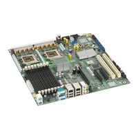
Intel S5000XVN - Workstation Board Motherboard Specification (107 pages)
Workstation Board
Brand:
Intel
| Category:
Motherboard
| Size: 1.78 MB
Table of Contents
Revision History
2
Table of Contents
3
1 Introduction
10
Chapter Outline
10
Server Board Use Disclaimer
10
2 Overview
11
Workstation Board Feature Set
11
Table 1. Workstation Board Features
11
Workstation Board Layout
12
Figure 1. Workstation Board Photograph
12
Workstation Board Connector and Component Layout
13
Figure 2. Major Board Components
14
Figure 3. Mounting Hole Positions
15
Workstation Board Mechanical Drawings
15
Figure 4. Component Positions
16
Figure 5. Restricted Areas on Side 1
17
Figure 6. Restricted Areas on Side 2
18
Figure 7. Restricted Areas on Side 2, "Detail B
19
Figure 8. CPU and Memory Duct Keepout
20
Figure 9. ATX I/O Layout
21
Workstation Board ATX I/O Layout
21
3 Functional Architecture
22
Figure 10. Functional Block Diagram
22
Intel ® 5000X Memory Controller Hub (MCH)
23
System Bus Interface
23
Processor Support
23
Table 2. Processor Support Matrix
23
Memory Subsystem
25
Figure 11. CEK Processor Mounting
25
Figure 12. Memory Layout
26
Table 3. I 2 C Addresses for Memory Module SMB
26
Table 4. Maximum Eight-DIMM System Memory Configruation - X8 Single Rank
27
Table 5. Maximum Eight-DIMM System Memory Configuration - X4 Dual Rank
27
Table 6. Maximum Eight-DIMM System Memory Configuration - X2 Quad Rank
27
Table 7. DIMM Population Rules
29
Figure 13. Minimum 2-DIMM Memory Configuration
30
Figure 14. Recommended Four DIMM Configuration
31
Figure 15. Single Branch Mode Sparing DIMM Configuration
32
Snoop Filter
33
Enterprise South Bridge (ESB2-E)
33
PCI Subsystem
33
Table 8. PCI Bus Segment Characteristics
34
Serial ATA Support
35
Parallel ATA (PATA) Support
36
USB 2.0 Support
36
Audio Codec
37
Figure 16. Audio Subsystem Block Diagram
37
SAS Controller
38
SAS RAID Support
38
SAS/SATA Connector Sharing
38
Network Interface Controller (NIC)
38
Figure 17. Rear I/O Panel Audio Connector
38
I/Oat)
39
MAC Address Definition
39
Table 9. NIC2 Status LED
39
3.6 Super I/O
40
Serial Ports
40
Floppy Disk Controller
40
Keyboard and Mouse Support
40
Wake-Up Control
40
Table 10. Serial B Header Pin-Out
40
System Health Support
41
Trusted Platform Module (TPM)
41
4 Platform Management
42
Figure 18. SMBUS Block Diagram
43
5 Connector/Header Locations and Pin-Outs
44
Board Connector Information
44
Table 11. Board Connector Matrix
44
Power Connectors
45
Table 12. Power Connector Pin-Out (J9B5)
45
System Management Headers
46
LCP/AUX IPMB Header
46
Table 13. 12-V Power Connector Pin-Out (J3J2)
46
Table 14. Power Supply Signal Connector Pin-Out (J9D1)
46
Table 15. P12V4 Power Connector Pin-Out (J5A2)
46
Table 16. LCP/AUX IPMB Header Pin-Out (J2J1)
46
IPMB Header
47
HSBP Header
47
SGPIO Header
47
Ses I 2 C
47
HDD Activity LED Header
47
Table 17. IPMB Header Pin-Out (J4J1)
47
Table 18. HSBP Header Pin-Out (J1J7, J1J2)
47
Table 19. SGPIO Header Pin-Out (J2H1, J1J5)
47
Table 20. SES I C Header Pin-Out (J1J3)
47
Table 21. HDD Activity LED Header Pin-Out (J2J3)
47
Front Panel Connector
48
I/O Connectors
48
NIC Connectors
48
Table 22. Front Panel SSI Standard 24-Pin Connector Pin-Out (J1E4)
48
Table 23. RJ-45 10/100/1000 NIC Connector Pin-Out (JA6A1, JA6A2)
48
IDE Connector
49
Table 24. IDE 40-Pin Connector Pin-Out (J2J2)
49
SATA/SAS Connectors
50
Serial Port Connectors
50
Table 25. SATA/SAS Connector Pin-Out (J1J1, J1H2, J1H1, J1G2, J1G1, J1F2)
50
Table 26. External DB9 Serial a Port Pin-Out (J7A1)
50
Keyboard and Mouse Connector
51
USB Connector
51
Table 27. Internal 9-Pin Serial B Header Pin-Out (J1B1)
51
Table 28. Stacked PS/2 Keyboard and Mouse Port Pin-Out (J9A1)
51
CD-IN Header
52
Audio Connectors
52
Table 29. External USB Connector Pin-Out (JA6A1, JA6A2)
52
Table 30. Internal USB Connector Pin-Out (J3J1)
52
Table 31. CD-IN Header Pin-Out (J4A1)
52
Fan Headers
53
Table 32. SSI 4-Pin Fan Header Pin-Out (J9J1, J5J1, J9B3, and J9B4)
53
Table 33. SSI 6-Pin Fan Header Pin-Out (J3H1, J3H2, J3H3, and J3H4)
53
6 Jumper Blocks
55
Figure 19. Jumper Blocks (J1C3, J1D1, J1D2, and J1E32)
55
Table 34. Server Board Jumpers (J1C3, J1D1, J1D2, and J1E3)
55
BMC Force Update Procedure
56
CMOS Clear and Password Reset Usage Procedure
56
BIOS Select Jumper
57
7 Intel Light Guided Diagnostics
58
Volt Standby LED
58
Figure 20. 5 Volt Standby Status LED Location
58
Fan Fault Leds
59
Figure 21. Fan Fault LED Locations
59
System ID LED and System Status LED
60
Figure 22. System ID LED and System Status LED Locations
60
Table 35. System Status LED
61
System Status LED - BMC Initialization
62
DIMM Fault Leds
62
Figure 23. DIMM Fault LED Locations
62
Processor Fault Leds
63
Post Code Diagnostic Leds
63
Figure 24. Processor Fault LED Locations
63
Figure 25. POST Code Diagnostic LED Location
64
8 Design and Environmental Specifications
65
Intel Workstation Board S5000XVN Design Specifications
65
Table 36. Workstation Board Design Specifications
65
Board-Level MTBF
66
Workstation Board Power Requirements
66
Figure 26. Power Distribution Block Diagram
67
Processor Power Support
68
Power Supply Output Requirements
68
Table 37. Intel ® Xeon ® Processor Dual Processor TDP Guidelines
68
Table 38. 550 W Load Ratings
68
Grounding
69
Remote Sense
69
Standby Outputs
69
Voltage Regulation
69
Capacitive Loading
70
Dynamic Loading
70
Table 39. Voltage Regulation Limits
70
Table 40. Transient Load Requirements
70
Ripple/Noise
71
Table 41. Capacitive Loading Conditions
71
Table 42. Ripple and Noise
72
Table 43. Output Voltage Timing
72
Timing Requirements
72
Figure 27. Output Voltage Timing
73
Table 44. Turn On/Off Timing
73
Figure 28. Turn On/Off Timing (Power Supply Signals)
74
Residual Voltage Immunity in Standby Mode
74
9 Regulatory and Certification Information
75
9.1 Product Regulatory Compliance
75
Product Safety Compliance
75
Product EMC Compliance - Class a Compliance
75
Certifications/Registrations/Declarations
76
Product Regulatory Compliance Markings
76
9.3 Electromagnetic Compatibility Notices
77
FCC Verification Statement (USA)
77
ICES-003 (Canada)
77
Europe (CE Declaration of Conformity)
78
VCCI (Japan)
78
BSMI (Taiwan)
78
RRL (Korea)
78
9.4 Restriction of Hazardous Substances (Rohs) Compliance
79
Appendix A: Integration and Usage Tips
80
Appendix B: BMC Sensor Tables
81
Table 45. BMC Sensors
83
Appendix C: POST Code Diagnostic LED Decoder
96
Figure 29. Diagnostic LED Placement Diagram
96
Table 46. POST Progress Code LED Example
96
Table 47. Diagnostic LED POST Code Decoder
97
Appendix D: POST Code Errors
100
Table 48. POST Error Messages and Handling
100
Table 49. POST Error Beep Codes
102
Table 50. BMC Beep Codes
102
Appendix E: Supported Intel Server Chassis
103
Glossary
104
Reference Documents
107
Advertisement
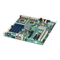
Intel S5000XVN - Workstation Board Motherboard User Manual (88 pages)
Workstation Board
Brand:
Intel
| Category:
Motherboard
| Size: 2.51 MB
Table of Contents
Safety Information
3
Wichtige Sicherheitshinweise
3
Consignes de Sécurité
3
Instrucciones de Seguridad Importantes
3
Important Safety Instructions
3
Warnings
5
Preface
7
About this Manual
7
Manual Organization
7
Product Accessories
8
Additional Information and Software
8
Table of Contents
11
Chapter 1: Workstation Board Features
19
Figure 1. Intel Workstation Board S5000XVN
19
Table 2. Workstation Board Features
20
Connector and Header Locations
22
Figure 2. Connector and Component Locations
22
Configuration Jumpers
24
Figure 3. Configuration Jumpers
25
Intel ® Light-Guided Diagnostics
26
Back Panel Features
29
Figure 4. Back Panel Connectors and Leds
29
Table 3. NIC Leds
29
RAID Support
30
SATA Workstation Board
30
SAS Workstation Board
31
Audio Support
32
Hardware Requirements
33
Processor
33
Memory
33
Figure 5. DIMM Sockets
34
Power Supply
35
Optional Hardware
36
Intel ® RAID Activation Key
36
Hard Disk Drives
36
Intel ® Local Control Panel
36
Chapter 2: System Utilities
37
Using the BIOS Setup Utility
37
Starting Setup
37
If You Cannot Access Setup
37
Setup Menus
38
Table 4. Setup Menu Key Use
38
Upgrading the BIOS
39
Preparing for the Upgrade
40
Upgrading the BIOS
40
Reverting to the Previous BIOS
41
Figure 6. BIOS Bank Select Jumper in Force Lower Bank Position
41
Clearing the Password
42
Figure 7. Password Clear Jumper in Clear Password Position
42
Clearing the CMOS
43
Figure 8. CMOS Clear Jumper in the Clear CMOS Position
43
Chapter 3: Hardware Installations and Upgrades
45
Before You Begin
45
Tools and Supplies Needed
45
Installing and Removing Memory
45
Installing Fbdimms
45
Figure 9. Locating DIMM Sockets
46
Figure 10. Installing Fbdimms
47
Removing Fbdimms
48
Installing or Replacing the Processor
48
Installing the Processor
49
Figure 11. Locating Processor Sockets
49
Figure 12. Opening Processor Socket Lever
50
Figure 13. Opening Load Plate
50
Figure 14. Removing Protective Cover from Load Plate
51
Figure 15. Setting Processor in Place
51
Installing the Heatsink(S)
52
Table 5. Heatsink Requirements for Compatible Intel ® Server Chassis
52
Figure 16. Installing Heatsink (Passive Heatsink Shown)
53
Figure 17. Locating Active Heatsink Cable Connections
54
Removing a Processor
55
Figure 18. Opening Processor Socket Lever
56
Figure 19. Opening Load Plate
56
Figure 20. Removing Processor from Socket
57
Figure 21. Installing Protective Cover Onto Load Plate
57
Replacing the CMOS Battery
58
Figure 22. Locating and Removing the CMOS Battery
59
Appendix A: Troubleshooting
61
System Boot Quiet Time
61
Resetting the System
61
Table 6. Resetting the System
61
Problems Following Initial System Installation
62
First Steps Checklist
62
Hardware Diagnostic Testing
63
Verifying Proper Operation of Key System Lights
63
Confirming Loading of the Operating System
63
Specific Problems and Corrective Actions
64
Power Light Does Not Light
64
No Characters Appear on Screen
65
Characters Are Distorted or Incorrect
66
System Cooling Fans Do Not Rotate Properly
66
CD-ROM Drive or DVD-ROM Drive Activity Light Does Not Light
66
Cannot Connect to a Server
67
Problems with Network
67
System Boots When Installing PCI Card
68
Problems with Newly Installed Application Software
68
Problems with Application Software that Ran Correctly Earlier
69
Devices Are Not Recognized under Device Manager (Windows* Operating System)
69
Hard Drive(S) Are Not Recognized
69
Bootable CD-ROM Disk Is Not Detected
70
LED Information
70
BIOS POST Beep Codes
70
Table 7. POST Error Beep Codes
70
Table 8. Error Beep Codes Generated by Intel ® Remote Management Module
71
Appendix B: Regulatory and Compliance Information
73
Product Regulatory Compliance
73
Product Safety Compliance
73
Certifications / Registrations / Declarations
74
Product Regulatory Compliance Markings
74
Table 9. Product Certification Markings
74
Electromagnetic Compatibility Notices
75
Fcc (Usa)
75
ICES-003 (Canada)
76
Europe (CE Declaration of Conformity)
76
VCCI (Japan)
76
BSMI (Taiwan)
77
RRL (Korea)
77
CNCA (CCC-China)
77
Product Ecology Change (EU Rohs)
78
Product Ecology Change (Crohs)
78
China Packaging Recycle Marks (or GB18455-2001)
80
CA Perchlorate Warning
80
End-Of-Life / Product Recycling
80
Appendix C: Getting Help
81
World Wide Web
81
Telephone
81
Latin America
82
Appendix D: System Issue Report Form
85
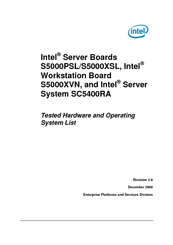
Intel S5000XVN - Workstation Board Motherboard Hardware Manual (69 pages)
Server/Workstation Board and Server System Tested Hardware and Operating System List
Brand:
Intel
| Category:
Motherboard
| Size: 0.36 MB
Table of Contents
Revision History
3
Table of Contents
4
1 Introduction
7
Test Overview
7
Basic Installation Testing
7
Adapter / Peripheral Compatibility and Stress Testing
8
Pass/Fail Test Criteria
9
2 Base System Configurations
10
Base System Configurations
11
3 Supported Operating Systems
12
Operating System Certifications
18
4 Adapters and Peripherals
24
SATA RAID Controller
25
SAS and SAS RAID Controller
28
SCSI and SCSI RAID Controllers
38
Fiber Channel
42
Nic
44
Modems
49
Removable Media
50
USB/PS2 Human Input Device
53
CD-ROM Drives
54
CD-RW Drives
55
CD-RW/DVD-ROM Drives
55
DVD+R/Rw
57
DVD Drives
58
Tape Drives
59
Kvm
60
Audio
61
Video
62
5 Hard Disk Drives
66
6 Installation Guidelines
67
List of Currently Unsupported Features for S5000PSLSATAR and S5000XVNSASR in Solaris 10 U4 08/07
67
Solaris 10 U4 (08/07) Requires Kernel Patch in Order for E54Xx and E52Xx Devices to Function Properly
67
Drivers for Solaris 10 U4 (08/07)
67
Onboard SATA (ESB2) Controller
68
Recommend to Install Following RAID Controllers in PCI Slot Other than Slot 4
69
Advertisement
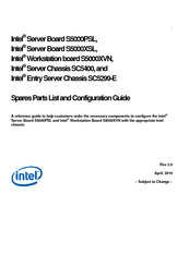
Intel S5000XVN - Workstation Board Motherboard Configuration Manual (26 pages)
Server/Workstation Board and Server / Entry Server Chassis Parts List
Brand:
Intel
| Category:
Motherboard
| Size: 0.21 MB
Table of Contents
Contents
3
Table of Contents
3
Production SKU Details and Contents
4
Production Configuration and Ordering Steps
4
Production Configuration and Ordering Steps (S5000XVN)
8
Production Configuration
12
Production Board Skus
15
Production Chassis
16
Production Spares and Accessories
18
Production RAID Products
23
Vmware Vsphere* Virtualization Software Configuration Guide for Vsphere* Skus
25
Advertisement
Related Products
Intel S5000PSL
Intel S5000PSLROMB
Intel S5000PSLROMBR - Server Board With Xeon Dualcore Support
Intel S5000PSLSAS
Intel S5000PSLSASR
Intel S5000VSA4DIMM
Intel S5000VSASASR - Xeon 50XX 51XX 53XX 54XX 4 SAS Port 8 FBDIMM Slots Motherboard
Intel S5000XVNSASR
Intel S5000XVNSATA
Intel S5000XVNSATAR
Intel Categories
Motherboard
Computer Hardware
Server
Server Board
Desktop
More Intel Manuals
Login
Sign In
OR
Sign in with Facebook
Sign in with Google
Upload manual
Upload from disk
Upload from URL