Vulcan-Hart E24L Service Manual
Electric ranges e24l, e36l, e48l and e60l series
Hide thumbs
Also See for E24L:
- Installation and operation manual (32 pages) ,
- Installation & operation manual (17 pages)
Advertisement
Table of Contents
- 1 Important Code, Safety and Warning Information
- 2 Data Plate, Electrical, and Appliance Clearance Information
- 3 Appliance Features
- 4 Section I Service Checks
- 5 Troubleshooting
- 6 Section II Service Adjustments
- 7 Section III Removal and Replacement of Serviceable Parts
- 8 Section IV Wiring Diagrams
- Download this manual
See also:
Operation & Installation Manual
Advertisement
Table of Contents

Related Manuals for Vulcan-Hart E24L


Summary of Contents for Vulcan-Hart E24L
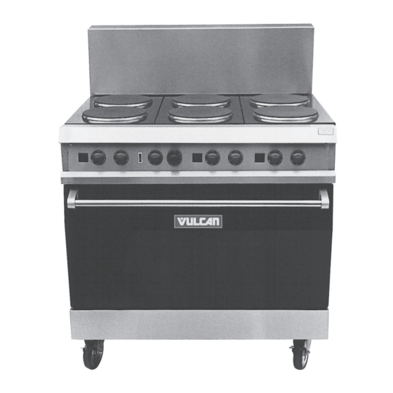
- Page 1 VULCAN-HART COMPANY, P.O. BOX 696, LOUISVILLE, KY 40201- 0696, TEL. (502) 778-2791 FORM 30900 SERVICE MANUAL FOR ELECTRIC RANGES MODELS E24L, E36L, E48L AND E60L SERIES ML NOS. 52361 THROUGH 52372 MODEL E36L SHOWN...
-
Page 2: Important Code, Safety And Warning Information
SERVICE MANUAL FOR ELECTRIC RANGES MODELS E24L, E36L, E48L AND E60L SERIES IMPORTANT FOR YOUR SAFETY THIS MANUAL HAS BEEN PREPARED FOR PERSONNEL QUALIFIED TO SERVICE AND ADJUST THE EQUIPMENT COVERED BY THIS MANUAL. INFORMATION ON THE CONSTRUCTION AND INSTALLATION OF VENTILATING HOODS MAY BE OBTAINED FROM THE "STANDARD FOR THE INSTALLATION OF EQUIPMENT FOR... -
Page 3: Table Of Contents
Single oven range with (6) french top plates or (2) high speed elements or (1) hot top section in place of (2) french plates in the vertical positions. E36FL = Single oven range with (2) french top plates and (1) 24" griddle top or (1) hot top section in place of the (2) french plates. E36XL = Single oven range with (1) 36"... -
Page 4: Section I Service Checks
SECTION I SERVICE CHECKS WARNING: UNPLUG OVEN BEFORE SERVICING. WARNING: CERTAIN PROCEDURES IN THIS SECTION REQUIRE ELECTRICAL TEST OR MEASUREMENTS WHILE THE POWER IS APPLIED. EXERCISE EXTREME CAUTION AT ALL TIMES. IF TEST POINTS ARE NOT EASILY ACCESSIBLE DISCONNECT POWER, ATTACH TEST EQUIPMENT AND REAPPLY POWER TO TEST. - Page 5 ON-OFF SWITCH CHECK 1. Follow steps 1-3 under the 4-Heat switch check except, using an ohmmeter check for continuity in the off position as follows: P1 to 2 P2 to 3 P2 to 4 If the above is not proven replace the switch.
-
Page 6: Troubleshooting
TROUBLESHOOTING PROBLEM Range is completely dead. Oven section elements are dead but top surface elements are working. Top element of the oven section is dead. Bottom element of oven section is dead. French plate or high speed element dead. Griddle element dead. - Page 7 TROUBLESHOOTING PROBLEM The circuit breaker trips after the range as been operating for a few minutes. CORRECTIVE ACTION The slow trip of a circuit breaker is an indication of overload in a particular circuit. The cause of this overload could be: Voltage problem, check element voltage against store and rating plate voltages.
-
Page 8: Section Ii Service Adjustments
SECTION II SERVICE ADJUSTMENTS WARNING: UNPLUG OVEN BEFORE SERVICING. WARNING: CERTAIN PROCEDURES IN THIS SECTION REQUIRE ELECTRICAL TEST OR MEASUREMENTS WHILE POWER IS APPLIED TO THE OVEN. EXERCISE EXTREME CAUTION AT ALL TIMES. IF TEST POINTS ARE NOT EASILY ACCESSIBLE DISCONNECT POWER, ATTACH TEST EQUIPMENT AND REAPPLY POWER TO TEST. - Page 9 THERMOSTAT ADJUSTMENT 1. Perform calibration check as stated under Section I. 2. Remove the thermostat knob. (Fig 3) 3. Insert a flat blade screwdriver into the thermostat dial stem until it reaches the calibration screw. 4. Note the calibrated center oven average as determined under Section 1 Calibration Check. Use that number as the calibration set point.
-
Page 10: Section Iii Removal And Replacement Of Serviceable Parts
SECTION III REMOVAL AND REPLACEMENT OF SERVICEABLE PARTS WARNING: UNPLUG OVEN BEFORE SERVICING. WARNING: CERTAIN PROCEDURES IN THIS SECTION REQUIRE ELECTRICAL TEST OR MEASUREMENTS WHILE POWER IS APPLIED TO THE OVEN. EXERCISE EXTREME CAUTION AT ALL TIMES. IF TEST POINTS ARE NOT EASILY ACCESSIBLE DISCONNECT POWER, ATTACH TEST EQUIPMENT AND REAPPLY POWER TO TEST. - Page 11 3. Fold control manifold cover down and rest it on the crumb tray. REMOVAL OF INFINITE SWITCH 1. Follow steps 1- 2 for dropping the control manifold cover. 2. Pull switch knob off of the control manifold cover. (Fig. 6) 4.
- Page 12 5. Lay the manifold cover down so that it rest on the crumb tray. (Fig. 8) 6. Note and remove the infinite switch wire connections. (Fig. 9) 7. Remove the switch from the appliance. 8. Reinstall new switch by reversing steps 1 through 6. Fig.
- Page 13 REMOVAL OF ON-OFF AND 4-HEAT SWITCHS (EGO Hot top only) 1. Pull crumb tray out about 6". 2. Remove the screws at the top left and right corners of the control panel. 3. Lower panel on to the crumb tray. 4.
- Page 14 REMOVAL OF INDICATOR LIGHTS 1. Follow steps 1-2 for dropping the control manifold cover. 2. Lay the manifold cover down so that it is resting on the crumb tray. 3. Locate the light from the rear of the cover. (Fig. 11) 4.
- Page 15 5. Squeeze the light mounting tabs in towards the light body casing and push the light through the manifold cover opening and out of the appliance. (Fig. 13) 6. Install new light by reversing steps 1 through 5. REMOVAL OF THERMOSTAT 1.
- Page 16 4. Note and remove all wiring associated with thermostat. (Fig. 15) 5. Lift up the left top aeration plate assembly to expose the top burner box area. (Fig. 16) Fig. 15 Fig. 16 6. Open the oven door. 7. Remove the oven rack(s). 8.
- Page 17 9. Locate the bulb access hole in the oven cavity, top left hand corner, and carefully feed the bulb and thermopile lead through the opening. (Fig. 18) 10. From the burner box top left side, pull the thermopile lead and bulb from the oven. (Fig. 19) Fig.
- Page 18 2. Lower control panel. 3. Using a ⁄ " socket remove (1) hex head retaining screw holding the range top mounting bracket to the front burner box cover. (Fig. 20) 4. Remove the backsplash. (See fig. 27) 5. Lift up on the aeration plate, push plate towards the rear of the unit, then lift plate assembly out and flip it over.
- Page 19 7. Note and remove (2) wires from the plate receptacle. (Fig. 22) 8. Remove the nut and locking bracket from the plate bottom. (Fig.23) Fig. 22 Fig. 23...
- Page 20 9. Lift plate out of the aeration plate top. 10. Install new french plate by reversing steps 1-9. REMOVAL OF HIGH SPEED ELEMENTS 1. Remove the back riser. 2. Flip over aeration plate to expose the element terminal ends and wiring. 3.
- Page 21 5. Install new element by reversing steps 1-4. When installing new element, be sure to align the element mounting tab with the mounting slot provided in the element ring before snapping the element firmly in place. (Fig. 26) HOT TOP PLATE/ELEMENT ASSEMBLY REMOVAL 1.
- Page 22 2. Using a ⁄ " socket, remove (2) hex head screws from the upper corners of the control panel. 3. Using a ⁄ " socket, remove the hex head screws holding the plate mounting bracket to the front burner box cover. (Fig. 28) 4.
- Page 23 6. Note and disconnect the wiring for the hot top section. (Fig. 30) Fig. 30 7. Reinstall hot plate by reversing steps 1 through 6.
- Page 24 REMOVAL OF GRIDDLE TOP 1. Remove riser or back guard. 2. Using a ⁄ " socket, remove (1) 10-24 screw from the front burner box securing the top mounting bracket to the appliance. (Fig. 31) 3. Tilt griddle up towards the back of the appliance. 4.
- Page 25 REPLACEMENT OF GRIDDLE TOP ELEMENTS 1. Follow steps 1-3 under removal of griddle top. 2. Using a ⁄ " socket, remove griddle base cover by disengaging (9) hex head bolts and lifting the cover off of the griddle assembly. (Fig. 33) 3.
- Page 26 REMOVAL OF OVEN BOTTOM 1. Open oven door. 2. Remove oven rack(s). 3. Lift oven bottom tray up and out of the appliance. (Fig. 35) REMOVAL OF THE BOTTOM OVEN ELEMENTS 1. Follow steps for removal of the oven bottom. 2.
- Page 27 3. Lower the kick panel. (Fig. 37) 4. With a ⁄ " socket, remove (2) screws holding the element terminal cover. Flip cover down. (Fig. 38) Fig. 37 Fig. 38...
- Page 28 5. Note and disengage element terminal wiring. (Fig. 39) 6. From inside the oven cavity, slip the bottom element out of the mounting clamps. Pull the element through the oven burner box and cavity area, out of the appliance. (Fig. 40) 7.
- Page 29 REPLACEMENT OF TOP OVEN ELEMENT 1. Flip over the left hand top section or aeration plate and let it lay over one of the center top sections. (See Fig. 21) 2. From the left hand side of the top burner box area, remove the rubber covers on the element terminal ends. (Fig.
- Page 30 4. Open oven door and remove the oven rack(s). (Fig.43) CAVITY AREA WITHOUT OVEN RACKS 5. Loosen (19) top element clamps using a Fig. 43 ⁄ " socket. (Fig. 44) LOOSEN SCREWS Fig. 44...
- Page 31 6. Slip the element out of the clamps (clamps may require removal if turning them will not free the element completely). 7. Pull the element through the top burner box outwards into the oven cavity and remove it from the appliance. 8.
- Page 32 4. From inside the oven cavity, located behind the front frame where the door is mounted, using a remove (2) nuts holding the door assembly to the trunnion block (1) on the left door side and (1) on the right. (Fig.
- Page 33 3. Using a ⁄ " socket wrench, remove (3) sheet metal screws securing the terminal block to the control housing. Remove the block from the appliance. (Fig. 48) 4. Install new terminal block by reversing steps 1-3. REPLACEMENT OF BREAKER 1.
- Page 34 4. With a ⁄ socket wrench, remove the sheet metal screws securing the breaker to the control housing and slip the breaker out of the appliance. Install new breaker by reversing steps 1-3. (Fig. 50) Fig. 50...
-
Page 35: Section Iv Wiring Diagrams
SECTION IV WIRING DIAGRAMS THE NEXT FOUR PAGES ARE DEDICATED TO WIRING INFORMATION OF THE E24L, E36L AND E60L ELECTRIC RANGES FOR ADDITIONAL WIRING INFORMATION CONTACT THE VULCAN-HART CO. SERVICE DEPARTMENT AT THE PHONE NUMBER LISTED ON THE BOTTOM FRONT COVER OF THIS MANUAL. - Page 36 E24L...
- Page 37 E36L...
- Page 38 E48L...
- Page 39 E60L...