Table of Contents
Advertisement
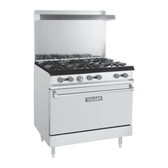
GAS RESTAURANT RANGE
EG24, 36, 48, 60, 160 AND 260
MODEL
EG24
EG36
EG48
EG60
EG160
EG260
V U L C A N - H A R T C O M P A N Y , P . O . B O X 6 9 6 , L O U I S V I L L E , K Y 4 0 2 0 1 - 0 6 9 6 , TEL. (502) 7 7 8 - 2 7 9 1
FORM 31054 Rev. A (5-98)
ML-52486
ML-52487
ML-114956
ML-52488
ML-52489
ML-52490
SERVICE MANUAL
EG36
Advertisement
Table of Contents

Related Manuals for Vulcan-Hart EG160


Summary of Contents for Vulcan-Hart EG160
- Page 1 SERVICE MANUAL GAS RESTAURANT RANGE EG24, 36, 48, 60, 160 AND 260 MODEL EG24 ML-52486 EG36 ML-52487 EG48 ML-114956 EG60 ML-52488 EG160 ML-52489 EG260 ML-52490 EG36 V U L C A N - H A R T C O M P A N Y , P . O . B O X 6 9 6 , L O U I S V I L L E , K Y 4 0 2 0 1 - 0 6 9 6 , TEL. (502) 7 7 8 - 2 7 9 1 FORM 31054 Rev.
-
Page 2: Important For Your Safety
IMPORTANT FOR YOUR SAFETY THIS MANUAL HAS BEEN PREPARED FOR PERSONNEL QUALIFIED TO INSTALL GAS EQUIPMENT, WHO SHOULD PERFORM THE INITIAL FIELD START-UP AND ADJUSTMENTS OF THE EQUIPMENT COVERED BY THIS MANUAL. POST IN A PROMINENT LOCATION THE INSTRUCTIONS TO BE FOLLOWED IN THE EVENT THE SMELL OF GAS IS DETECTED. -
Page 3: Gas Restaurant Range Models
GAS RESTAURANT RANGE MODELS EG60 EG160 EG260 EG48 EG24 EG36 PL-53006 – 4 –... -
Page 4: Table Of Contents
SERVICE MANUAL GAS RESTAURANT RANGES INDEX PLEASE KEEP THIS MANUAL FOR FUTURE REFERENCE DESCRIPTION PAGE SERVICE NOTATIONS UNITS MOUNTED ON CASTERS SERVICING SIMPLE CHECKS AND ADJUSTMENTS 7-10 GAS CONNECTIONS 11, 12 TESTING THE GAS SUPPLY SYSTEM ORIFICE SIZE REQUIREMENTS FOR DIFFERENT ELEVATIONS PILOT LIGHTING AND ADJUSTMENTS 13-17 THERMOSTAT ADJUSTMENTS... -
Page 5: Service Notations
1. The procedures outlined in this manual are to be performed only by Vulcan-Hart authorized service representatives. 2. An authorized Vulcan-Hart service representative is one who is familiar with Vulcan equipment and who has been endorsed by Vulcan-Hart Company to service the equipment. All authorized service personnel are required to stock a minimum amount of parts and should be equipped with a complete set of wiring diagrams, service and parts manuals covering all Vulcan-Hart equipment. -
Page 6: Units Mounted On Casters
UNITS MOUNTED ON CASTERS Units mounted on casters utilizing a flex hose and quick-disconnect must be installed with a restraining device. The restraining device must be connected at all times. If disconnection of the device is necessary, turn off the gas supply before disconnection. - Page 7 SERVICING SIMPLE CHECKS AND ADJUSTMENTS (Cont.) 2. Oven Door Turnbuckle NOTE: For the 24L units, refer to procedure outlined under 2A. If the oven door is not closing properly, the door turnbuckle may require adjustment. To adjust the turnbuckle, flip down the lower front kick panel.
- Page 8 SERVICING SIMPLE CHECKS AND ADJUSTMENTS (Cont.) 3. Pilot Flame Height TOOLS REQUIRED: Standard flat blade screwdriver. Top Burners: To adjust pilot flame height of the unit top burners, locate the pilot adjustment screws found on the front manifold pipe. It is not necessary to remove the manifold cover, as adjustment access holes have been provided in the panel.
- Page 9 SERVICING SIMPLE CHECKS AND ADJUSTMENTS (Cont.) 2. With screwdriver, adjust pilot key (located under pilot adjustment cap) to provide the proper size flame. 3. Replace pilot adjustment cap. NOTE: If unit still is not heating correctly, refer to THERMOSTAT ADJUSTMENTS on Page 18. 4.
-
Page 10: Gas Connections
Standard units are equipped with fixed burner orifices which coincide with the proper unit operation elevation. See Orifice Size Requirements for Different Elevations on Page 12. NOTE: Do not attempt to drill out orifice sizes. Obtain proper conversion kit from Vulcan-Hart depot. Install the gas pressure regulator. -
Page 11: Testing The Gas Supply System
GAS CONNECTIONS (Cont.) NOTE: A leak limiter is supplied with every regulator to allow excess gas pressure to escape. Do not obstruct leak limiter on gas pressure regulator as obstruction may cause regulator to malfunction. WARNING: PRIOR TO LIGHTING, CHECK ALL JOINTS IN THE GAS SUPPLY LINE FOR LEAKS. USE SOAP AND WATER SOLUTION. -
Page 12: Pilot Lighting And Adjustments
All adjustment procedures associated with pilot lighting must be performed by an authorized Vulcan-Hart installation or service person. While performing these procedures, do not turn the burner valves “ON” with the burner heads removed. - Page 13 PILOT LIGHTING AND ADJUSTMENTS (Cont.) OPEN TOP BURNERS 1. Turn main gas supply “ON”. 2. Wait 30 seconds and, using a taper, light the open top pilot (Fig. 10). Fig. 10 3. If pilot fails to light, turn main gas supply “OFF”. Wait 5 minutes and repeat the above procedures. 4.
- Page 14 PILOT LIGHTING AND ADJUSTMENTS (Cont.) BROILER/GRIDDLE 1. Turn main gas supply “ON”. 2. Wait 30 seconds and, using a taper, light broiler/griddle pilot (see Fig. 9). 3. If pilot fails to light, turn main gas supply “OFF”. Wait 5 minutes and repeat Steps 1 and 2. 4.
- Page 15 PILOT LIGHTING AND ADJUSTMENTS (Cont.) 2. Light pilot by depressing the reset button located behind the kick panel (Fig. 12). Light pilot and continue to hold reset button in for 1 minute. If pilot fails to light, turn main gas supply “OFF” and wait 5 minutes before repeating Step 2. 3.
- Page 16 PILOT LIGHTING AND ADJUSTMENTS (Cont.) OVEN BURNER ADJUSTMENTS NOTE: These procedures should be performed only by a qualified Vulcan-Hart service representative. TOOLS REQUIRED: Standard flat blade screwdriver. All Restaurant Range series units equipped with pressure regulator and fixed orifices have been adjusted at the factory and should require no further adjustments.
-
Page 17: Thermostat Adjustments
THERMOSTAT ADJUSTMENTS NOTE: These procedures should be performed only by a qualified Vulcan-Hart service representative. STANDARD OVEN Although the unit thermostats are factory positioned to their proper setting, it is not unusual for the thermostat to be knocked out of adjustment during shipment. If the oven or griddle heat response seems to be lacking after burner air shutter adjustments have been checked, perform the following adjustments. - Page 18 THERMOSTAT ADJUSTMENTS (Cont.) 3. Light the burner. Turn the dial to the highest set temperature. 4. After 10 minutes, turn the dial clockwise to the point slightly beyond the first mark on the dial (shown by an “X”). 5. Remove the dial and sleeve (Fig. 17). Fig.
- Page 19 THERMOSTAT ADJUSTMENTS (Cont.) 3. Allow unit to heat until the burner flame is heard cutting “OFF”. Wait about 10 minutes until the burner flame has cycled “ON” and “OFF” several times. Then compare the test instrument reading with the dial setting. If the reading is within ±...
-
Page 20: Thermostat Adjustments
THERMOSTAT ADJUSTMENTS (Cont.) 10. To recalibrate, hold the thermostat dial in place. Insert screwdriver into dial shaft to engage the calibration stem adjustment screw (Fig. 20). Push inward (do not turn stem). Fig. 20 11. While holding stem calibration screw in place, turn thermostat dial until it is set on the actual temperature shown by the testing device (Fig. -
Page 21: Regulator Check, Adjustment, Installation
REGULATOR CHECK, ADJUSTMENT, INSTALLATION REGULATOR CHECK A regulator is installed on each range. When servicing this equipment for possible gas pressure problems, the following visual checks should be made first. Make sure the regulator has been installed at the rear of the unit with arrow pointing in the horizontal position in the direction of gas flow. - Page 22 REGULATOR CHECK, ADJUSTMENT, INSTALLATION (Cont.) 2. With only two open top burners “ON”, note the manometer reading. The reading should be 3.7" Water Column (.92 kPa) for natural gas units and 10.0" Water Column (2.5 kPa) for propane gas units. If readings taken are lower, check the incoming line pressure.
-
Page 23: Regulator Check, Adjustment, Installation
REGULATOR CHECK, ADJUSTMENT, INSTALLATION (Cont.) 1. Connect the manometer to the pressure tap provided on the rear manifold pipe (see Fig. 23). 2. Check the reading. The reading should be 3.7" Water Column (.92 kPa) for natural gas and 10.0" Water Column (2.5 kPa) for propane gas. -
Page 24: Standard Oven & Griddle Thermostat Replacement
STANDARD OVEN & GRIDDLE THERMOSTAT REPLACEMENT STANDARD OVEN AND GRIDDLE THERMOSTAT CHECKS AND CALIBRATION Refer to THERMOSTAT ADJUSTMENTS on Page 18 of this manual for the procedures for checking and calibrating the thermostat for the standard oven and griddle. STANDARD OVEN AND GRIDDLE THERMOSTAT REPLACEMENT TOOLS REQUIRED: Pipe wrench, 6"... - Page 25 STANDARD OVEN & GRIDDLE THERMOSTAT REPLACEMENT (Cont.) 4. From inside the oven, straighten the capillary lead. From the opening in the oven top section, pull the capillary out of the oven cavity (Fig. 29). Fig. 30 5. Remove the top section burner valve knobs, top grates and aeration plate. (Figs. 30) 6.
- Page 26 STANDARD OVEN & GRIDDLE THERMOSTAT REPLACEMENT (Cont.) 9. Unscrew the thermostat from the manifold pipe (Figs. 33, 34, & 35). Fig. 34 Fig. 33 Fig. 35 10. Replace thermostat mounting block. Place pipe dope on the threaded end of the new thermostat mounting block to be installed onto the unit.
-
Page 27: Oven Pilot Check, Replacement
OVEN PILOT CHECK, REPLACEMENT OVEN PILOT CHECK If all other systems have been checked and pilot will not stay lit, replacement of the pilot may be necessary. OVEN PILOT REPLACEMENT TOOLS REQUIRED: ⁄ " socket, socket driver, ⁄ " and ⁄... -
Page 28: Standard Oven Pilot Safety Valve Check, Replacement
If the unit pilot is “ON” but the unit is not heating, check the gas flow from the thermostat to the safety valve, using a flow meter (Fig. 36). (Flow meter kits are available from Vulcan-Hart Service Parts Depots under Part No. 495.) FOR PROPER USAGE OF FLOW METER, REFER TO THE MANUFACTURER’S INSTRUCTIONS PROVIDED IN... - Page 29 STANDARD OVEN PILOT SAFETY VALVE CHECK, REPLACEMENT (Cont.) Fig. 37 5. If the millivolt reading is below 5 MV, replace the thermocouple. 6. If the MV reading is within tolerance, the safety valve should be replaced. SAFETY VALVE REPLACEMENT PROCEDURES TOOLS REQUIRED: ⁄...
- Page 30 STANDARD OVEN PILOT SAFETY VALVE CHECK, REPLACEMENT (Cont.) 3. Disconnect right- and left-hand pilot gas tubing from the safety valve (Fig. 39). Fig. 39 4. Disconnect right- and left-hand burner gas tubing from the safety valve (Fig. 40). Fig. 40 5.
-
Page 31: Thermocouple Check, Replacement
THERMOCOUPLE CHECK, REPLACEMENT THERMOCOUPLE CHECK 1. Fold lower kick panel down. 2. Perform pilot lighting procedures (see Page 13). 3. If unit will not stay lit, using a volt meter, check the millivolt reading from the valve thermocouple connection while holding pilot button in the “ON”... -
Page 32: Oven Burner Nozzle And Orifice Check, Replacement
BTU rating with flow meter. (Flow meter kits are available from Vulcan-Hart Service Parts Depots under Part No. 420000.) FOR PROPER USAGE OF FLOW METER, REFER TO THE MANUFACTURER’S INSTRUCTIONS PROVIDED IN THE FLOW METER KIT. -
Page 33: Oven Burner Check, Replacement
OVEN BURNER CHECK, REPLACEMENT OVEN BURNER CHECK If the oven burner is not properly firing and all other systems have been checked, the oven burner may need to be cleaned or replaced. OVEN BURNER REPLACEMENT TOOLS REQUIRED: ⁄ " socket and socket driver. 1. -
Page 34: Top Section Pilot Check, Replacement
TOP SECTION PILOT CHECK, REPLACEMENT TOP SECTION PILOT CHECK If all other systems have been checked and pilot will not stay lit, cleaning or replacement of pilot may be necessary. TOP SECTION PILOT REPLACEMENT TOOLS REQUIRED: ⁄ " open end wrench. 1. -
Page 35: Top Section Burner Valve And Nozzle Check, Replacement
TOP SECTION BURNER VALVE AND NOZZLE CHECK, REPLACEMENT TOP SECTION BURNER VALVE CHECK After a long period of use on the range, the top section burner valve can show signs of wear. Check valve for gas leakage and sloppy valve control. Check also for valve nozzle blockage or damage. TOP SECTION BURNER VALVE AND NOZZLE REPLACEMENT TOOLS REQUIRED: ⁄...