Table of Contents
Advertisement
Available languages
Available languages
Owner's
Manual/Manual
IDei Propietario
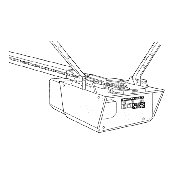
1/2 HP
315MHz
GARAGE
DOOR OPENER
ABRIDOR
DE PUERTA
DE COCHERA
For Residential
Use Only/S61o
para uso residenciai
Model/Modelo
139.53920D
315MN_
m
Z
r==
!
m
¢,/}
ZI
r==
Read and follow
all safety rules
and operating
instructions
before
first use of this product.
Fasten the manual near the garage
door after installation.
Periodic
checks
of the opener
are
required
to ensure
safe operation.
Leer y seguir todas
las reglas
de
seguridad
y las instrucciones
de
operaci6n
antes de usar este
producto
por primera
vez.
Guardar
este manual cerca de la
puerta de la cochera.
Se deben
realizar
revisiones
peribdicas
del abridor
de puertas
para asegurar
su operacibn
segura.
Sears,
Roebuck
and Co., Hoffman
Estates,
IL 60179
U.S.A
www sears com!craflsman
Advertisement
Table of Contents

Related Manuals for Craftsman 139.53920D


Summary of Contents for Craftsman 139.53920D
- Page 1 Owner's Manual/Manual 1/2 HP 315MHz GARAGE ABRIDOR DE PUERTA For Residential Use Only/S61o Model/Modelo 139.53920D Read and follow all safety rules and operating instructions first use of this product. Fasten the manual near the garage door after installation. Periodic checks...
-
Page 2: Table Of Contents
Symbol Signal Word Review This garage door opener has been designed and tested to offer safe service provided it is installed, operated, maintained and tested in strict accordance with the instructions and warnings contained in this manual Mechanical Electrical Adjustment Adjust the travel limits ... -
Page 3: Preparing Your Garage Door
Preparing your garage Before you begin: • Disable locks • Remove any ropes connected to garage door . Complete the following test to make sure your garage door is balanced and is nat sticking or binding: 1 Lift the door about halfway as shown Release the door If balanced, it should stay in place, supported entirely by its springs 2 Raise and lower the door to see if there is any... -
Page 4: Planning
Planning Identify the type and height of your garage door Survey your garage area to see if any of the conditions below apply to your installation, Additional materials may be required,, You may find it helpful to refer back to this page and the accompanying illustrations as you proceed with the installation of your opener Depending on your requirements, there are several... - Page 5 Planning (Continued) ONE-PIECE DOOR INSTALLATIONS o Generally, a one-piece door does not require reinforcement, If your door is lightweight, refer to the information relating to sectional doors in Installation Step 11, o Depending on your door's construction, you may need additional mounting hardware for the door bracket (Step 11)_ ONE-PIECE DOOR WITHOUT...
-
Page 6: Carton Inventory
Carton inventory Your garage door opener is packaged in one carton which contains the motor unit and all pads illustrated below Accessories witf depend on the model purchased If anything is missing, carefully check the Door Control B[Jtten SIngle_Function with... -
Page 7: Hardware Inventory
Hardware Bnventory Separate all hardware and group as shown below for the assembly and installation procedures © Lock 1/4"-20 Belt 1/4_-20xl-314" T_'otley Threaded Cardege Bolt Wing 1t4"-20xl/2" t/4"-20 Lag Screw 5It 6*-9x t-5/8" 5116"-18x!-718" Carriage Boll 5116"-18x2-l/2" Clevis 5/16"xl -lY2' ASSEMBLY HARDWARE ©... -
Page 8: Assemble The Rail And Install The Troiley
ASSEMBLY STEP Assemble Rail & Instaff To avoid installation difficulties, garage door opener until instructed The front rail has a cut out "window"at the door end (see illustration), The hole above this window is larger on the top of the rail than on the bottom A smaller hole 3-1/2"... -
Page 9: Fasten The Rail To The Motor Unit
ASSEMBLY STEP Fasten Rail Motor • Insert a 1/4"-20xl-3/4 bolt into the cover protection bolt hole on the back end of the rail as shown,, Tighten securety with a 1/4"-20 lock nuL Do NOT overtighten, ° Remove the two bolts from the top of the motor unit. -
Page 10: Install The Chain/Cable
ASSEMBLY STEP Hnstall Chain/Cable 1 Pull the cable around the idler pulley and toward the trolley. 2 Connect the cable to the retaining slot on the trolley, as shown (Figure 1): • From below, push pins of master link bar up through cable link and trolley slot •... -
Page 11: 3Ghten The Chain
ASSEMBLY STEP Tighten Chain • Spin the inner nut and lock washer down the trolley threaded shaft, away from the trolley.. - To tighten the chain, turn outer nut in the direction shown (Figure 1). ,, When the chain is approximately 1/4" (6 mm) above the base of the rail at its midpoint, reqighten the inner nut to secure the adjustment. -
Page 12: Determine The Header Bracket Location
IINSTALLATIOH STEP Determine Header Location To prevent possible SERIOUS INJURYor DEATH: • Headerbracket MUSTbe RIGIDLY fastenedto structural support on headerwall or ceiling, otherwise garagedoor might net reversewhen required= DO NOT install headerbracketover drywall,, - Concreteanchors MUSTbe used if mounting header bracketor 2x4 into masonry - NEVER try to loosen, move or adjust garagedoor, springs, cables,pulleys,brackets,or their hardware,... -
Page 13: Install The Header Bracket
tiHSTALLAT!ION STEP install Header Bracket You can attach the header bracket either to the wall above the garage door, or to the ceiling. Follow the instructions which will work best for your particular requirements. Do not install the header over drywall. If installing into masonry, concrete anchors... -
Page 14: Attach The Rail To The Header Bracket
mNSTALLATmON Attach Bracket NOTE: (Optional) With some existing installations, you may re-use the old header bracket with the two plastic spacers included in the hardware bag, Place the spacers inside the bracket on each side of the rail, as illustrated . -
Page 15: Position The Opener
nNSTALLATHON STEP Position Opener Follow instructions which apply to your door type as glustrated SECTIONAL DOOR OR ONE-PIECE TRACK A 2x4 laid flat is convenient for setting an ideal door-to-rail distance . Remove foam packaging. . Raise the opener onto a stepladder You will need help at this point if the ladder is not tall enough, - Open the door all the way and place a 2x4 laid flat on the top section beneath the rail,... -
Page 16: Hang The Opener
NSTALLATION STEP Hang Opener Three representative installations are shown.. Yours may be different Hanging brackets should be angled (Figure 1) to provide rigid support. On finished ceilings (Figure 2 and Figure 3), attach a sturdy metal bracket to structural supports before installing the opener. -
Page 17: Install The Door Control
INSTALLATllON STEP Install Door Control Locate door control within sight of door, at a minimum height of 5 feet (1.5 m) where small children cannot reach, away from moving parts of door and door hardware. 1 Strip 1/4" (6 mm) of insulation from one end of bell wire and connect to the two terminal screws on back of door control by color: white to 2 and white/red to 1... -
Page 18: Install The Light
. To remove, reverse the procedure. Use care to avoid snapping off lens tabs.. o Use A19, standard neck garage door opener bulbs for replacement. NOTE: Use only a standard light bulb The use of a short neck or speciality light bulb may overheat the endpanel or light socket. -
Page 19: Electrical Requirements
NSTALLATmON STEP _ENectrical Requirements To avoid installation difficulties, do not run the opener at this time. To reduce the risk of electric shock, your garage door opener has a grounding type ptug with a third grounding pin This plug will only fit into a grounding type outlet If the plug doesn't fit into the outlet you have, contact a qualified electrician to install the proper outlet... -
Page 20: Insta!L The Protector System
UNSTALLAT|OH STEP Install Protector System The safety reversing sensor must be connected and aligned correctly before the garage door opener wilt move in the down direction. IMPORTANT INFORMATION ABOUTTHE SAFETY REVERSING SENSOR When properly connected and aligned, the sensor will detect an obstacle in the path of its electronic beam, The sending eye (with an amber indicator tight) transmits an invisible light beam to the receiving eye (with a green indicator light),, If an... - Page 21 INSTALLING THE BRACKETS Be sure power to the opener is disconnected. Install and align the brackets so the sensors wilt face each other across the garage door, with the beam no higher than 6" (t5 cm) above the floor installed in one of three ways, as follows.
- Page 22 MOUNTING AND WIRING THE SAFETY REVERSING SENSORS , Slide a t/4"-20xl/2" carriage bolt head into the slot on each senso_ Use wing nuts to fasten sensors to brackets, with lenses pointing toward each other across the door Be sure the fens is not obstructed by a bracket extension (Figure 5) ,, Finger tighten the wing nuts.
-
Page 23: Fasten The Door Bracket
NSTALLATmON STEP Fasten Door Bracket Follow instructions which apply to your door type as illustrated below or on the following A horizontal reinforcement brace enough to be secured to two vertical vertical reinforcement brace should height of the top panel. The illustration shows one piece of angle iron as the horizontaf... - Page 24 ONE-PIECE DOORS PTease read and comply with the warnings reinforcement instructions on the previous They apply to one-piece doors also,, . Center the door bracket on the top of the door, in line with the header bracket as shown Mark either the left and right, or the top and bottom holes - Drii! 5/16"...
- Page 25 IHSTALLATllON STEP Connect Door Trolley Follow instructions which apply to your door type as illustrated below and on the following page SECTIONAL DOORS ONLY • Make sure garage door is fully closed Pull the emergency release handle to disconnect the outer trolley from the inner trolley Slide the outer trolley back (away from the pulley) about 8"...
-
Page 26: Connect The Door Arm To The Trolley
ALL ONE-PIECE DOORS 1.Assemble the door arm, Figure 4: • Fasten the straight and curved door arm sections together to the longest possible length (with a 2 or 3 hole overlap) • With the door closed, connect the straight door arm section to the door bracket with the 5/16"x1-1/4"... -
Page 27: Adjust The Travel Limits
ADJUSTMENT STEP Adjust UP and DOWN Limits Limit adjustment settings regulate the points at which the door will stop when moving up or down. To operate the opener, press the Door Control push bar. Run the opener through a complete travel cycle. , Does the door open and close completely? •... -
Page 28: Adjustment
ADJUSTMENT STEP Adjust Force Force adjustment controls are located on the back panel of the motor unit. Force adjustment settings regulate the amount of power required to open and close the door If the forces are set too light, door travel may be interrupted by nuisance reversals in the down direction and stops in the up direction. -
Page 29: Test The Safety Reversal System
The door will not move more than an inch (25 cm), and the opener lights will flash The garage door opener will not close from a remote if the indicator light in either sensor is off (alerting you to the fact that the sensor is misaligned or... -
Page 30: Operation
• The wall-mounted Door Control,: Hold the push button or bar down until the door starts to move. • The Keyless Entry (See Accessories): If provided with your garage door opener, it must be programmed before use_See Programming.. When the opener is activated (with the safety reversing sensor correctly installed and aligned) 1..If open, the door wil! close. -
Page 31: Using The Wall-Mounted Door Control
Using Wall-Mounted Door Control Press the push button to open or close the door, Press again to reverse the door during the closing cycle or to stop the door while it's opening To Open Door Manually To preventpossible SERIOUS INJURYor DEATH from a falling garagedoor: . -
Page 32: Care Of Your Garage Door Opener
CARE OF YOUR GARAGE DOOR OPENER LIMIT AND FORCE FORCE CONTROLS ADJUSTMENTS: Weather conditions cause some minor changes in door operation requiring some re-adjustments, particularly during the first LIMIT CONTROLS year of operation, Pages 27 and 28 refer to the limit and force adjustments Only a screwdriver required... -
Page 33: Having A Problem
1.My door will not close and the light bulbs blink on my motor unit: The safety reversing sensor must be connected and aligned correctly before tile garage door opener will move in the down direction - Verify the safety sensors are properly installed, aligned and free of any obstructions. -
Page 34: Diagnostic Chart
Motor Circuit Failure, Replace Receiver Logic Board. Your garage door opener is programmed with self-diagnostic capabilities. The "Learn" button!diagnostic LED will flash a number of times then pause signifying it has found a potential issue. Consult Diagnostic Chart below. Symptom:... -
Page 35: Programming
Your garage door opener has already been programmed at the factory to operate with your hand-held remote control, The door will open and close when you press the large push butlon. Below are instructions for programming your opener to operate with additional Security+ _ remote controls=... -
Page 36: Keyless Entry Pin
The keypad will blink four times when one button close is deactivated.. Change a Keyless to operate your garage door opener. To change If the existing PIN is known, it may be changed one person without using a [adder 1. Press the four buttons for the present PIN, then... -
Page 37: Repair Parts
REPAIR PARTS Installation Parts PART 41A4166 10A20 41A6140-2 29B137 41A2828 41A5047 41B4494-1 41A5047-2 178B35 41A5034 4tA5266-1 178B34 12B776 41A5258-10 114A3421 PART DESCRIPTION 4A1008 Master link kit 41 C5141-1 Complete trolley assembly 41A5665-2 Complete rail 144C56 idler pulley 41A5807 Chain and cable 12D598-1 "U"... -
Page 38: Motor Unit Assembly Parts
Motor Unit Assembly Parts (Cowl1) LIMIT Brown Contact ASSEMBLY Wire \./'_ ',-_.._ Drlva Gear =_"_4_J"_ Cenler _'_it Contact Conlact PART DESCRIPTION 41A5615 Chain Spreader 4t C4220A Gear and sprocket Complete with: Spring washer, Thrust washert Bearing plate, Roll pins (2), Drive gear and worm gear;... -
Page 39: Accessories
From the 91st day and through 4 years, if the motor on this product is detective, a replacement motor will be furnished free of charge This Craftsman Garage Door Opener Limited Warranty does not cover iighI bulbs or repair pads necessary because of operator abuse... - Page 40 CONTKNIDO Introducci6n RevisiOn de los sfmbelos y t_rminos de seguridad ...2 Preparaci6n de la puerta de su cochera ... Herramientas necesarias ... PfanificaciOn ... Inventario de ta caja de carton ... Inventario de piezas ... Montaje Monte el tie! y instale el trole Fije el riel a la unidad del motor ...
- Page 41 PreparaciGn de la puerta su cochera Antes de comenzar: - Quite ros seguros - Retire cualquier cuerda o cable que est_ conectado aia pue_a., " Haga la siguiente prueba con su puerta para verificar que est_ ba]anceada y que no se atore ni se pandee: 1.
- Page 42 Pianificaci6n Identifique ]a a[tura y el tipo de su pueda Revise et ,irea de su cochera y obserVe si alguna de ias siguientes instataciones corresponden A races se requieren maleriales adicionafes, vez sea conveniente toner asia hoja y ]as ilustraciones correspondientes a mano cuando inicie la instalaci6n...
- Page 43 Planificaci6n (continUa) INSTALACION CON PUERTAS DE UNA SOLA PIEZA Generatmente una puerta de una so{a pieza no requiem refuerzos adicionales S[ usted tiene una puerta de material liviano y quiere reforzarla_ consulte informaci6n respecto a puertas seccionales, en tnstalaci6n, Paso 11 Dependiendo det diseSo de su puerla, piezas de montaje...
- Page 44 nnventario de la Caja de CartOn Su abridor viene empacado en una caja de cart6n que contiene el motor y las piezas que se muestran siguiente ilustraci6n, Tome nota de que los accesofios dependeMn det modeIo que haya comprado aFguna pieza, revise con cuidado el material ya queen ocasiones...
- Page 45 Hnventario de Piezas Antes de Ia instalaci6n, organice redes [as piezas en grupos come se muestra en [a siguiente ilustraci6n Tue_ca de 114-20(2} Pemoda 114-20×I-314 pu_g (2) Recha re,cede del 1role ($) TORNILLERiA Teema d _mariposa Peme de coche V,I-2O pulg { 2) de 114,20xl/2 pu!g {2) TORNILLERt'A...
- Page 46 iu,t,un,U,,,UUItUU,Ul UI,.JI.JI,,, MONTAJE, PASO Monte el Riel e instale el Trole No encienda ni use el abridor hasta que Ilegue at paso de ta instalaci6n correspondiente, manera corre el riesgo de compticar instalaci6n. El riot dotantero tiene una "ventana" cortada extreme de la puerta (yea la ilustraciSn)
- Page 47 MONTAJE, PASO Fije el Riel a la Unidad del Motor Coloque un perno de 1/4-20xl-3/4 odficio de ta cubierla de protecci6n el extremo posterior del riel, como se indica en la ilustraciOn, Apriete bien el pemo con tuerca 1/4-20 de pulg NO ajuste demasiado Quite dos pernos de la parte superior...
- Page 48 PASO #nstale ia Cadena y Cable 1 Jale el cable atrededor de la polea loca y hacia el trole, 2 Conecte la came a ta ranura de retenci6n se muestra en la Hustraci6n (Figura ,, Empuje los pernos de la barra de enlace desde abajo hacia aniba y p_seles del cable y Ia ranura del trole , Empuje la tapa deJ enlace...
- Page 49 MONTAJE, PASO Apriete ia Cadena ,' Gire la luerca intema y ajuste la arandela; per el eje roscado del trole, alei_,ndolas • Pare apretar la cadena, gire la tuerca extema direcciSn que se indica (Figura • Una vez que ia cadena est6 aproximadamente (114 de pulg ) per encima de ta base det de[ en su punto...
- Page 50 INSTALACI6N, PASO Determine d6nde va a instalar ia M_nsula del Cabezal ADVERTENCIA Par° evitar una posible LESION GRAVE 0 INCLUSO t_ MUERTE: • La mdnsula del cabezat DEBE quedar RiGIDAMENTE sujeta at soporte °structural en ta pared delantera o en el cielo raso, de no set asi as p0sible que fa puerta do la coehe_a no retroceda cuando se requiera NO instate Ia m_nsula del cabezat an meres raises,...
- Page 51 I'HUH INSTALACIOIHI, PASO Instale la M_nsula del Cabezal La m#,nsula de! cabezal se puede fijar a la pared ]usto per encima de la puerta de la cochera o en el cielo raso Siga fas instruccienes que sean m_s adecuadas pare su cochera.
- Page 52 IINSTALACi6N, Coloque dei Cabezal NOTA: (Opcional) puede reutitizar dos espaciadores de componentes, de la m#nsula, en la ilustracidn, • Coloque de ia m6nsula como base para protegedo, puerta est# obstruyendo, persona sobre un soporte pueda librar et resorte • Coloque m_nsula pasador muestra...
- Page 53 INSYALACI6N, PASO' 4 Coloque el Abridor en Posici6n Siga tas instrucciones correspondientes de su cochera, como se muestra en la itustraci6n PUERTA SECCIONAL O PUERTA DE UNA SOLA PIEZA CON CARRIL Un pedazo de madera de 5x10 cm (2x4 pulg,) le ser_ de ayuda al determinar la distancia ideat entre [a puerta...
- Page 54 =,u=,,,,u, ,,,,,,, mNSTALACaON, PASO Cueigue el Abridor Aquf se muestran tres ejemplos distintos instalaci6n; sin embargo, es posible que su cochera concuerde con ninguno de elles Las m6nsu[as deben estar en _ngulo (Figure 1), para que proporcionen un soporte figido, En case de tener un cielo raso acabado (Figure 2 y Figure 3), instale una m6nsula resistente...
- Page 55 ii,lllu ,,,,,i mNSTALACaON, PASO lnstale la Unidad de Control Ubique el control de la puerta de manera que quede vista desde la puerta y a una attura mfnima de I 5 m (5 pies) donde los niSos pequefios no in puedan ]ejos de fas partes mSviles de ta puerta y de Ia tornilleria 1, Pe]e 6 mm (t/4 de pulg ) del extremo...
- Page 56 _NSTALACaON, PASO Hnstale ia Luz • Insta_e bombillo de hasta 75 vatios come m_.ximo en cada poda]_.rnpara. Los bombillos deben set de A19 cuetlo estandar s61o. En cuanto se conecte electricidad, la luce se ENCENDER,_N encendidas per aproximadamente cuatro minutes medio;...
- Page 57 gNSTALACgON, PASO Bequisitos para la Instalaci6n Para evitar dificultades con ta instalaci6n, ni use ei abridor en este memento,, Para reducir el riesgo de cheque el_ctrico, puerta de cochera viene con una davija tierra de tres paras, Esta ctavija s61o se puede conectar una toma de corfiente puesta a tierra y con tres entradas...
- Page 58 I,JIL i ,L_LU_,L, INSTALACmON, PASO Nnstale La Sistema de Protecci6n El sensor del sistema de retroceso ester instalado y alineado eorrectamente, el abridor de la puerta de cochera mueva hacia abajo, INFORMACI(_N 1MPORTANTE CON RESPECTS AL SENSOR DEL SlSTEMA DE RETROCESO DE SEGURIDAD Si se instate y se alinea correctamente, sistema...
- Page 59 INSTALACION DE LAS MENSULAS AsegL_rese de que et abridor no est_ conectado corriente el_ctrica. lnstale y alinee las m_nsulas de manera que los sensores est#n uno frente al otto en los tados opuestos puerto, a una distancia maxima de 15 cm (6 pulg,) piss Instale las m_nsulas...
- Page 60 MONTAJE Y CABLEADO DE LOS SENSORES SISTEMA DE RETROCESO DE SEGURIDAD . Deslice la cabeza de un pemo de coche de I/4_20xl/2 de pulgada dentro de la ranura de Ion sensores tuercas de mariposa para sujetar los sensores m6nsulas, con las lenten de cada sensor frente a frente aambos tados de la puerta CerciSrese...
- Page 61 nNSTALACm6N, PASO Fije la M_nsula de la Puerta Siga las instrucciones que correspondan al tips de puerta de cochera que usted |enga, come se muestra ilustraciSn o en la p,_gina siguiente Si usa un puntal horizontal, _ste debe set to suficientemente largo para sujetarlo...
- Page 62 PUERTAS DE UNA SOLA PIEZA Lea y respete todas tas advertencias e instrucciones respecto a los refuerzos, contenidas en ta pAgina anterior, Instalaci6e de puertas seccionales, ya que lodes los refuerzos para su puerta de una sola pieza son los mismos ,' Cotoque ta m_nsula de la pueda...
- Page 63 "NSTALACION, PASO Conecte el Brazo de la Puerta Siga las instrucciones que correspondan de cochera que usted tenga, come se muestra a continuaci6n la p_gina siguiente SOLO PARA PUERTAS SECCIONALES • Cerci6rese de que la puerta de Ia cechera compfetamente cerrada Tire de ta manija de emergencia para desconectar...
- Page 64 TODAS LAS PUERTAS DE UNA SOLA 1. Arme el braze de la puerta, Figura - Sujete las dos secciones de los brazes de ta puerta (recto y curve) a la mayor distancia manera que dos o tres de {es orificios se sobrepongan uno a[ otro ,, Cierre la puerta y fije ]a secci6n recta del braze a la...
- Page 65 AJUSTES, PASO Ajuste el L_mite del Recorrido HACIA ARRIBA y HACIA ABAJO Af ajustar el Iimite det recorrido de la puerta,se reguta basra qu_ punts _sta se detendr,_ al abrir y al cerrar Para porter en marcha el abridor, oprima et botSn de controf de ta puerta Haga funcionar ei abridor...
- Page 66 AJUSTES, PASO Ajuste la Fuerza Los controles para el ajuste de la fuerza del abfidor encuentran en el panel de posterior de la unidad del motor Estos ajustes controIarAn la fuerza que ser& necesada para abfir y cerrar la puerta, Si la fuerza es muy d#bi], es posible que Ia pueda...
- Page 67 AJUSTES, PASO Pruebe el Sisterna de Retroceso Seguridad PRUEBA • Abra completamente ta puerta, coloque madera de 3.8 cm (1-1/2 de pulg ) (o un pedazo de madera de 5x10 cm (2x4 pulg) acostado en el centre de ta puerta de ta cochera. •...
- Page 68 OPERACRON INSTRUCC,ONES Para reducir 1 LEA Y SIGA TODAS LAS ADVERTENCIAS Y LAS fNSTRUCCIONES DE OPERACI(_N 2 SIEMPREconservelos centrolesremotos fuera dot alcance de ios niBos NUNCApermita qua !os nifios operen o jueguen con ios botonEsdel control de ta puerta de la cochErani con los c0ntroles rem0t0s 3 SOLOactive la pueda de la cocherasiempre y cuandola puedaver con claridad,est6 debidamenteajustaday no haya...
- Page 69 C6rno Usar la Unidad de Control de Pared Oprima el bot6n iluminado para abrir o cerrar la puerta, Optima de nuevo para que ta puer_a retroceda en el cicto de cierre o para detener puerta cuando se estA abfiendo C6mo Abrir Para evitar [a posibilidad de una LESION GRAVE o INCLUSO LA MUERTE si la pueda de ]a cochera se eae:...
- Page 70 _IANTSNIMgEHTO DE SU ABRIIDOR DE PUERTA COCHERA AJUSTES DE LIMITE Y FUERZA: Las condiciones CON'mOLES DE FUERZA climatoi6gicas pueden ocasionar cambios menores en ta operaciOn de ta puerta, los cuates van a requerir algunos reajustes, en particular durante e! primer aOo de operaci6n.
- Page 71 TI]ENE ALGgN PROBLEMA 1_ La puerta no cierra y las luces de la unidad parpadean: El sensor del sistema de retroceso de segundad debe estar instatado y alineado para que el sistema de apedura de la puerta de la cochera se mueva en sentido descendents •...
- Page 72 Tabla de Diagn6stico S[ntoma: permanecen Et circuito de los sensores • lnspeccione de retroceso de seguridad estd abierto (cable rote o desconectado)._ • Desconecte 0 BIEN • Quite los sensores . Vue_va a conectar Hay un cortocircuito en el cable de los sensores retroceso de seguridad, los cables blanco...
- Page 73 C6MO PROGRAMAR EL ABRIIDOR AVISO: Si utitiza este abre puertas de garaje (cSdigo aleatorio), se vergn circunvenidas los aparatos de captura de cddigos El propietario comprador ni af proveedor de un transmisor dichas medidas t#cnicas. Su abridor de puerta de cochera ya viene programado abrir_ y se cerrar,_ cuando oprima...
- Page 74 C6rno Agregar, Reprograrnar NOTA: Su nueva Entrada sin lfave debe programarse come USAR EL BOT6N LEARN (APRENDER) 1 Optima y suette el bot6n "Aprender" de ta unidad del moto_ La tuz indicadora de este bot6n estar_ encendida per 30 segundos 2 En los 30 segundos, introduzca n0mero de identificaci6n...
- Page 75 ACCESORmOS 139+53702 Liberador de la Ilave de emergencia: Se requiere en las cocheras tienen puerta de acceso dueff, o de ]a casa abfir la puerta de la cochera manua_mente desconectando el trote 139+53726 Extensi6n del riel de 2+4 m (8 pies): Permite que una puerta de 24 m (B pies) se abra comptetamente...
- Page 76 Get it fixed, at your home or ours! For repair-in lawn and garden equipment, no matter For the replacement owner's For Sears professional and items like garage door openers 1-800-4-NIY-HOiVIE Call anytime, For repair of carry-in and electronics, Call anytime, To purchase or maintenance agreement...