
Related Manuals for CyberPower CPSPV36000ETLA-WB


Summary of Contents for CyberPower CPSPV36000ETLA-WB
- Page 1 CPSPV36000ETLA-WB CPSPV33000ETLA-WB CPSPV30000ETLA-WB CPSPV22000ETLA-WB User’s Manual Cyber Power Systems, Inc. www.CyberPower.com K01-0000937-00...
-
Page 2: Table Of Contents
6.4.1 Using ‘ModbusFwUpgrade’ to Update firmware .............. 31 6.4.2 Monitor the inverters ........................ 31 6.4.3 RS485 cable connection......................32 7 Start-Up and shut down the inverter ................. 33 7.1 Start-Up the inverter ..........................33 User Manual 1 / 40 CPSPV36000ETLA-WB series... - Page 3 10.1 Dismantling the Inverter ........................37 10.2 Packing the Inverter ........................... 37 10.3 Disposing of the Inverter ......................... 38 11 Specification..........................38 11.1 Specification of CyberPower Mini Central Series ..............38 11.2 Torque Values ............................40 12 Contact ............................40 User Manual...
-
Page 4: Information On This Manual
CPSPV36000ETLA-WB series. Store this manual where accessible at all times. 1.2 Target Group This manual is for qualified persons such as PV system installers or electricians. Notes: For possible changes in this manual, Cyber Power Systems, Inc. accepts no responsibilities to inform the users 1.3 Symbols Used... -
Page 5: Safety
2 Safety 2.1 Intended Use CPSPV36000ETLA-WB series inverters are to be used solely to feed solar energy converted solar energy into the public grid. CPSPV36000ETLA-WB series inverters are multi-string inverters with multi-MPP trackers and may only be operated in compliance with its intended use in grid-tie PV system. -
Page 6: Safety Precautions
2.3 Safety Precautions The CPSPV36000ETLA-WB series is designed and tested according to international safety requirements; however, certain safety precautions must be observed when installing and operating this inverter. Reading and follow all instructions, cautions and warnings in this installation manual. -
Page 7: Electrical Connection Warnings
Energy is fed directly into the public grid. The solar Public inverter need install a separate energy meter. The grid: energy produced compensated rate depending on the electric power company. User Manual 6 / 40 CPSPV36000ETLA-WB series... -
Page 8: Operation Warnings
To avoid electric shock, removing the front covert only after disconnecting both AC and DC for 2 minutes. Direct Current (DC) Alternating Current (AC) CE mark. The inverter complies with the requirements of the applicable EC guidelines. User Manual 7 / 40 CPSPV36000ETLA-WB series... -
Page 9: Product Description
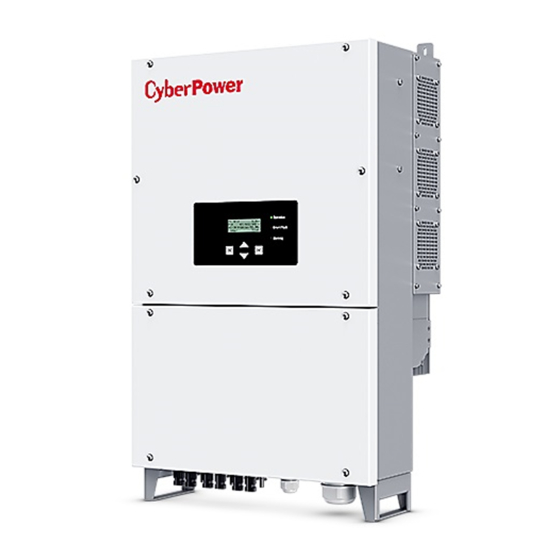
View Bottom View Position Description LCD (Charter 20*4) LED (Green/Red/Yellow) Buttons (Up/Down/Enter/Esc) PV input terminals DC Switch Water proof gland for RS-485 Water proof gland for AC output Protective Earthing Screw DC Switch User Manual 8 / 40 CPSPV36000ETLA-WB series... -
Page 10: Type Label
3.2 Type label The type labels provide a unique identification of the inverter (The type of product, Device-specific characteristics, Certificates and approvals). The type labels are on the right-hand side of the enclosure. User Manual 9 / 40 CPSPV36000ETLA-WB series... -
Page 11: Size And Weight
3.3 Size and weight Dimension A(mm) B1/B2(mm) C(mm) Weight(kg) CPSPV36000ETLA-WB 460/495 47.0 series User Manual 10 / 40 CPSPV36000ETLA-WB series... -
Page 12: Transportation
If there are lots of inverters need to be stored, the maximum layers for original carton is five. After long term storage, local installer or service department of CyberPower should perform a comprehensive test before installation User Manual... -
Page 13: Unpacking
Do not install the inverter on easily flammable materials and where flammable materials are stored. Risk of burns due to hot enclosure parts Mount the inverter in such a way that it cannot be touched inadvertently. User Manual 12 / 40 CPSPV36000ETLA-WB series... -
Page 14: Selecting The Installation Location
10) Notice the minimum clearances between inverters should be at least 800mm. (Refer to 3.3 Dimensions and Fig.5.9 Required Clearances). 11) Do not install the inverter near television antenna or any other antennas and antenna cables. User Manual 13 / 40 CPSPV36000ETLA-WB series... -
Page 15: Installation Guide
Drill 4 holes for screws while use the mounting frame as template. Fix the mounting frame on the wall as the figures shown below, combine as the screws as the Items Fig 4.1 shows (items D) User Manual 14 / 40 CPSPV36000ETLA-WB series... -
Page 16: Installation Layout
Avoid exposing inverter to direct sunlight, rain or snow to extend the inverter service life despite the IP65 protection degree. Exposure to the sunlight may cause additional internal Fig. 5.8 More than one inverter need to be installed, the dimensions below should be considered. Fig. 5.9 User Manual 15 / 40 CPSPV36000ETLA-WB series... -
Page 17: Mounting Inverter
After the bracket is firmly mounted on the wall, then mount the inverter on the bracket. Rise up the CPSPV36000ETLA-WB a little higher than the bracket. Considering the weight, you need to hang on the inverter. During the process please maintain the balance of the... -
Page 18: Wiring Ac Output
Please do not use single-core wire cable. The single-core wire is too hard to wire and might make water-proof cable gland losing its function. To Wire AC Power Cable onto inverter, To open the Wiring Box of CPSPV36000ETLA-WB series. Tool -Allen Key #4 required on this Step. User Manual... -
Page 19: Wiring Dc Input
This will void all warranty claims. Do not connect strings to the inverter that have an open-circuit voltage greater than the maximum input voltage of the inverter. User Manual 18 / 40 CPSPV36000ETLA-WB series... - Page 20 The maximum PV String currents are list below, Type Max. per string current CPSPV36000ETLA -WB series In order to seal the inverter, all unused DC inputs must be closed with sealing plugs: Solar Cable requirements: User Manual 19 / 40 CPSPV36000ETLA-WB series...
-
Page 21: Grounding
If PV modules of the PV system require POSITIVE or NEGATIVE to connect to GROUND, the output of inverter should connect to grid with an isolating transformer. The connection method is below: Invert Note , Neutral point of transformer should not be connected to PE under such application. User Manual 20 / 40 CPSPV36000ETLA-WB series... -
Page 22: Grid Type
Connection Inverter Connection TN-CS grid TT grid Home Home Inverter Grid Inverter Transformer Transformer Grid Connection Connection IT grid Home Transformer Inverter Grid Connection Grid type TN-C TN-S TN-C-S Inverter CPSPV36000ETLA-WB Yes, series User Manual 21 / 40 CPSPV36000ETLA-WB series... -
Page 23: Commissioning
Shutdown Mode Inverters automatically stop running during periods of little or no sunlight. In shutdown mode the inverters take no power from the grid and panel, and the LCD and LED turns off automatically. User Manual 22 / 40 CPSPV36000ETLA-WB series... -
Page 24: To Operate With Lcd Display
6.3 To operate with LCD Display There are 4 buttons, 3 LEDs & 1 LCD display on CPSPV36000ETLA-WB series. When inverter powered on by either solar power or utility at its initial, the Display show our Brand and product Model name as following picture. -
Page 25: Display Root
C.: input voltage, current, and power of MPPT C. ►Meter Grid Output: U. 231V/48.4A/11.1kW V. 230V/48.5A/11.2kW W. 232V/48.5A/11.1kW PV Input: A. 671V/38.0A/25.5kW B. 664V/37.0A/24.6kW C. 664V/37.0A/24.6kW #A1-A2 10.1/10.1 #B1-B2 10.1/ 7.6 #C1-C2 10.1/10.1 User Manual 24 / 40 CPSPV36000ETLA-WB series... - Page 26 Configuration General Settings Grid Settings Inputs Settings Return to Default Return to Factory 6.3.2.5.1 General Settings This interface displays parameters of inverter, including date, time, language and RS485ID.Please refer to Ch9. User Manual 25 / 40 CPSPV36000ETLA-WB series...
- Page 27 1. When at the language interface ‘Language:’ the option is ‘English’ in default. By single Clicking, languages will vary from one to another. >Date: 2018-09-09 >Date: 2017-09-09 Time: 15:18 Time: 15:18 Language Language RS485ID RS485ID User Manual 26 / 40 CPSPV36000ETLA-WB series...
- Page 28 This operation required password .If you do require modification, please contact qualified technical person for the modification. 1. The default code, utility standard is ‘VDE0126-1-1/2013’.The item can be modified by operation with display of inverter. CyberPower can configure this item before delivery to customer. Notice, When one modifies details of code, such as overvoltage protection limit, the code will automatic transform to “custom”.
- Page 29 U Hi-on Recovery voltage after inverter shunt down due to over grid frequency limit U Lo-off Under grid frequency limit T Lo-off Time delay for under grid frequency limit U Lo-on Recovery voltage after inverter shunt down due to under frequency limit User Manual 28 / 40 CPSPV36000ETLA-WB series...
- Page 30 Voltage Protection Freq. Protection ►Recon.T 300 s Max. Power 50000 W 4. Inverter max power settings, For CPSPV36000ETLA-WB, the maximum allowable power is 36000W. Voltage Protection Freq. Protection Recon.T 300 s ►Max. Power 36000 W 5. Insulation resistance setting The item is set for limit to resistor between PV panels and earth.
- Page 31 There are two item Separate and Parallel. Separate is each MPPT performs maximum power tracking independently and used for PV site. Parallel is reserved for factory test in CyberPower. The setting will be configured as “Separate” before its delivery. ►Conn. Type ►Separate...
-
Page 32: Communication
Communicating… 6.4 Communication 6.4.1 Using ‘ModbusFwUpgrade’ to Update firmware About the software CPS PVI Firmware Upgrade , please download from CyberPower official website. For more detail information about firmware upgrade, please refer to service manual or contact with CyberPower. 6.4.2 Monitor the inverters The inverter provides RS485 interface to communicate with remote PC or logger. -
Page 33: Rs485 Cable Connection
6.4.3 RS485 cable connection 1. Open “COMM.” (Communication) cover from bottom wiring CPSPV36000ETLA-WB series by Phillips screwdriver. 2. Unplug the RS484 interface card from its socket illustrate in Sec 3.1. RS485 terminator Switch, - Default OFF - On for 120Ω... -
Page 34: Start-Up And Shut Down The Inverter
The air grills or cooling fans are clogged. To clean the air grills and cooling fans One or two cooling fans failed. To exchange the cooling fans Ventilation of installation location is poor. Choose appropriate installation location before mounting. User Manual 33 / 40 CPSPV36000ETLA-WB series... -
Page 35: Trouble Shooting
An error message will be displayed on the LCD screen when a fault occurs. The faults consist of system fault and inverter fault. You may be advised to contact CyberPower in some situation, please provide the following information. Information concerning the inverter: Serial number ... -
Page 36: System Fault
DC voltage of MPPT2 is PV3 under voltage This usually happened among sunrise or sunset. lower than 250Vdc HW Fan Fans Failed To clear all fans or replace fan SPD break SPD damage. To replace SPD User Manual 35 / 40 CPSPV36000ETLA-WB series... -
Page 37: Inverter Fault
2. Inverter locate in bad ventilation. Temperature sensor Temperature sensor is Please Contact with CyberPower service fail open or short Inverter failed its DSP ADC1 calibration during Please Contact with CyberPower service initialization. -
Page 38: Decommissioning
This might cause by unstable grid .Inverter will AC HW OCP AC output over current automatically recovery once the voltage in range. If this keep happened, please Contact with CyberPower service. DC Aux Power Failed by Aux PWR Fail Please Contact with CyberPower service... -
Page 39: Disposing Of The Inverter
Ensure that the old unit and, where applicable, any accessories are disposed of in a proper manner. 11 Specification 11.1 Specification of CyberPower Mini Central Series CPSPV36000ETLA-WB CPSPV33000ETLA-WB CPSPV30000ETLA-WB CPSPV22000ETLA-WB Input (DC) Nominal. PV power... - Page 40 CE, IEC 62109 CE, IEC 62109 EN61000-6-2 / EN61000-6-2 / EN61000-6-2 / EN61000-6-2 / EN61000-6-3 / EN61000-6-3 / EN61000-6-3 / EN61000-6-3 / EN61000-3-11 / EN61000-3-11 / EN61000-3-11 / EN61000-3-11 / EN61000-3-12 EN61000-3-12 EN61000-3-12 EN61000-3-12 User Manual 39 / 40 CPSPV36000ETLA-WB series...
-
Page 41: Torque Values
Serial number of Inverters Error code of Inverters Display of inverter Cyber Power Systems, Inc. No.26, Jinzhuang Rd., Neihu Dist., Taipei City 114, Taiwan (R.O.C.) Service line TEL: +886-2-2651-8699 FAX: +886-2-2651-6821 E-mail: service@CyberPower.com User Manual 40 / 40 CPSPV36000ETLA-WB series...