Table of Contents
Advertisement
Quick Links
Advertisement
Table of Contents

Related Manuals for CyberPower CPSHB300ETR


Summary of Contents for CyberPower CPSHB300ETR
- Page 1 User’s Manual CPSHB300ETR Cyber Power Systems, Inc. www.cyberpower.com...
-
Page 3: Table Of Contents
Contents 1 Information on this Manual ....................... 1 1.1 Validity ..........................1 1.2 Target Group ........................1 1.3 Symbols Used........................1 2 Safety ............................2 2.1 Intended Use ........................2 2.2 Safety Precautions ......................2 2.3 Assembly Warnings ......................3 2.4 Electrical Connection Warnings .................. - Page 4 9 Decommissioning ........................23 9.1 Dismantling the Inverter....................23 9.2 Packing the Inverter ......................23 9.3 Disposing of the Inverter ....................23 10 Specification .......................... 24 10.1 Specification of CPSHB300ETR ..................24 10.2 Torque Values ......................... 25 11 Contacts ..........................26...
- Page 5 Table of Figures Fig. 2-1 Energy storage system ......................2 Fig. 3-1 Layout of CPSHB300ETR ......................6 Fig. 3-2 Dimensions of CPSHB300ETR ....................7 Fig. 4-1 Components included in the scope of deliver ................8 Fig. 5-1 Permitted and prohibited installation positions ............... 10 Fig.
- Page 6 Table of Figures Table 6-1 Charge current setting ......................15 Table 6-2 LEDs indicators for On Grid operation ................. 16 Table 6-3 LEDs indicators for Off Grid operation ................. 17 Table 10-1 Specification ........................24 Table 10-2 Torque values ........................25...
-
Page 7: Information On This Manual
1.2 Target Group This manual is most suitable for users who have basic knowledge around electricity and electrical devices. Note: CyberPower Systems, Inc. will not inform users for any changes taken place within this guide. 1.3 Symbols Used The following types of safety instructions and general information appear within this document:... -
Page 8: Safety
The CPS hybrid series is designed and tested according to international safety requirements; however, certain safety precautions must be observed when installing and operating this inverter. Read and follow all instructions, cautions and warnings in this installation manual. User Manual Hybrid CPSHB300ETR... -
Page 9: Assembly Warnings
Grounding the PV modules: Comply with the local requirements for grounding the PV modules and the PV generator. CyberPower recommends connecting the generator frame and other CAUTION electrically conductive surfaces in a manner which ensures continuous conduction and ground these in order to have optimal protection of the system and personnel. -
Page 10: Electrical Connection Warnings
(e.g. when sensitive equipment is located at the setup location or when the setup location is near radio or television receivers).In this case, the operator is obliged to take proper action to rectify the situation. User Manual Hybrid CPSHB300ETR... -
Page 11: Symbols On The Inverter
2 minutes. Risk of burns The product’s surfaces are hot during operation. Don’t touch during operation. Don’t dispose of the product together with the household waste. In accordance with the applicable disposal regulations for electronic waste. User Manual Hybrid CPSHB300ETR... -
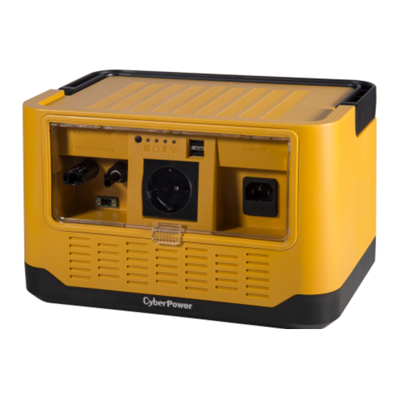
Page 12: Product Description
PV Input Connectors External Battery Connector AC-out Power Outlet AC-in Power Outlet / GRID Tool for Removing PV Connectors 3.2 Size and Weight The dimensions of CPSHB300ETR as Fig. 3-2, the weight is 9kg includes batteries. User Manual Hybrid CPSHB300ETR... -
Page 13: Transportation
. And the storage relative humidity should be always between 0 and 95%. ℃ ℃ After long term storage, local installer or service department of CyberPower should perform a comprehensive test before installation 3.5 The Advantage of CPS Hybrid PV Inverters... -
Page 14: Unpacking
Fig. 4-1 Components included in the scope of deliver Item Quantity Description Hybrid PV Inverter Power cord for AC connection User manual & Warranty Card Even though packaging is made to be durable, please treat it gently and Information avoid tossing it around. User Manual Hybrid CPSHB300ETR... -
Page 15: Installation
The ambient temperature of the inverter should be -10℃~+50℃. The installation location must be freely and safely to get at all times. Vertically installation only. Never install in horizontal positions, and avoid forward and sideways tilting; (observe drawings below) User Manual Hybrid CPSHB300ETR... -
Page 16: Electrical Connections
NEVER connect or disconnect the DC connectors under load. Risk of damage to the inverter. If the voltage of the PV modules exceeds the maximum input voltage of NOTICE the inverter, it can be destroyed by the overvoltage. This will void all User Manual Hybrid CPSHB300ETR... -
Page 17: Wiring External Battery Input
Loose the screw of battery connector by screwdriver and pull out the connector. Tight connector screws after you insert battery-wires to lock them into place. An AWG14 wire type is recommended. Place the battery connector back to the inverter and tight it into place. User Manual Hybrid CPSHB300ETR... -
Page 18: Fig. 5-4 Connect Pv Connectors To Inverter
Fig. 5-4 Location of extended battery connector User Manual Hybrid CPSHB300ETR... -
Page 19: Wiring Ac Output
LEDs will display as below. PV power would be transferred to charge the batteries. PV >27V and <50V (Off) Connects inverter Grid O/P to electrical socket, it will bypass the Grid power to standalone output automatically. Under normal operating conditions, the Grid LED turns green. User Manual Hybrid CPSHB300ETR... -
Page 20: Operation Modes
LEDs to save energy but keep monitoring the internal system for quickly going back to normal operation. When PV power comes back, inverter will enter charger mode automatically. When PV power is gone, inverter will enter shutdown mode. User Manual Hybrid CPSHB300ETR... -
Page 21: Charge Current Setting
Now, user can change the charge current by pressing button (refer to Table 6-1 for the setting). Table 6-1 Charge current setting Charge Current PV Panel Battery AC/On-Grid Off-Grid Orange / Orange Green and Red alternately Orange Orange User Manual Hybrid CPSHB300ETR... -
Page 22: Leds Indicators
Normally and 75% and under charging slowly operating flashing Green Green Operating normally with battery capacity between 25% and 50% and under Orange with charging<24.5Vdc and ≧ slowly 23Vdc and charging flashing User Manual Hybrid CPSHB300ETR... - Page 23 Orange Countdown the status of Off Grid operation battery Green Flash Output Operating normally, supply power from power from PV and battery to *A, *B PV and loads Green Green battery User Manual Hybrid CPSHB300ETR...
- Page 24 <22V if Pout <30W (*A) -> Color: depend on the remaining capacity. (*B) -> Flashing frequency: charging is slow, discharging is fast. (*C) -> If Off-Grid operation transfers from On-Grid mode and Grid is abnormal. User Manual Hybrid CPSHB300ETR...
-
Page 25: Start-Up And Shut-Down The Inverter
2. Turn on the DC switch or connect PV connectors, press and hold the button of inverter until Off-Grid LED is green (release the button immediately when that LED is green). 3. Inverter will start Off-Grid operation if the input voltage is higher than 27V or battery voltage is User Manual Hybrid CPSHB300ETR... -
Page 26: Shut-Down The Inverter
1. If inverter is operating, press and hold the button until all LEDs are red, it takes around 3 seconds. 2. Disconnect the AC/Grid power cord. 3. Disconnect all PV connectors. 4. When all LEDs are OFF, the inverter will totally shutdown. User Manual Hybrid CPSHB300ETR... -
Page 27: Maintenance
Battery cover Battery Fig. 8-1 Procedure of replacing batteries Disconnect the 2 batteries from inverter and replace them with new ones. Connect the new batteries to inverter, notice the polarity! Assemble the inverter in reverse order. User Manual Hybrid CPSHB300ETR... -
Page 28: Replace The Fuse
Pull out the fuse holder underneath the AC/Grid socket. Replace the broken fuse with new one. Note the rating must be 6.3A/250V P Place the fuse assembly back into the AC/Grid socket. Fig. 8-2 Grid O/P fuse replacement User Manual Hybrid CPSHB300ETR... -
Page 29: Decommissioning
Do not dispose of faulty inverters or accessories together with household waste. Please accordance with the disposal regulations for electronic waste which apply at the installation site at that time. Ensure that the old unit and, where applicable, any accessories are disposed of in a proper manner. User Manual Hybrid CPSHB300ETR... -
Page 30: Specification
Specification 10.1 Specification of CPSHB300ETR Table 10-1 Specification CPSHB300ETR PV Input Max. input power 310W Absolute max. input voltage 50Vdc Full power voltage range 34-38Vdc Operating voltage range 28-48Vdc Rated input voltage 36Vdc Max. input current 9Adc MPP Tracker Voltage: <2% Measurements deviation Current: <2%... -
Page 31: Torque Values
-20-40℃ Storage temperature Relative humidity 0-95% Operating elevation 0-2000m (0-6666ft) Cooling Natural convection Mechanical Dimension (W*H*D, mm) 292*186*202 Weight Package dimension 380*305*290 (W*H*D, mm) 10.2 Torque Values Table 10-2 Torque values Battery cover screws 10kgf.cm (0.98N.m) User Manual Hybrid CPSHB300ETR... -
Page 32: Contacts
11 Contacts If you have technical problems concerning our products, contact your installer or CyberPower. During inquiring, please provide below information: Model Name Serial Number Detailed Error Description Cyber Power Systems, Inc. www.cyberpower.com User Manual Hybrid CPSHB300ETR... - Page 33 Note...
- Page 34 Note...
- Page 36 K01-0000591-00...