
Related Manuals for CyberPower CPSPV30000ETL-WB


Summary of Contents for CyberPower CPSPV30000ETL-WB
- Page 1 CPSPV30000ETL-WB CPSPV33000ETL-WB CPSPV40000ETL-WB User’s Manual CyberPower Systems Inc. www.cyberpower.com Index...
-
Page 2: Table Of Contents
CONTENTS INFORMATION ON THIS MANUAL ..................3 ..................................3 ALIDITY ................................ 3 ARGET ROUND ................................3 YMBOLS SAFETY ........................... 4 ................................4 NTENDED ..............................5 AFETY RECAUTIONS ..............................5 SSEMBLY ARNINGS ..........................5 LECTRICAL ONNECTION ARNINGS ..............................6 PERATION ARNINGS PRODUCT DESCRIPTION ...................... - Page 3 ................................31 DISPLAY ............................. 31 NVERTER INFORMATION ..............................32 ISPLAY PERATION COMMUNICATION ......................38 10.1 ‘S _3P’ & ..............38 SING OLAR OWER ETUP PDATE FIRMWARE MONITOR INVERTER 10.2 ............................38 ONITOR THE INVERTERS 10.3 RS485 ............................39 CABLE CONNECTION MAINTENANCE AND CLEANING ..................
-
Page 4: Information On This Manual
Store this manual where accessible at all times. 1.2 Target Ground This manual is for qualified persons such as PV system installers or electricians. Notes: For possible changes in this manual, CyberPower Systems, Inc. accepts no responsibilities to inform the users 1.3 Symbols Used... -
Page 5: Safety
If PV modules of the PV system require POSITIVE or NEGATIVE grounding, , please contact CyberPower Systems, Inc. for technical support before installation. User Manual... -
Page 6: Safety Precautions
Grounding the PV modules: Comply with the local requirements for grounding the PV modules frame and the PV generator. CyberPower strongly recommends grounding the generator frame in order to have optimal earth protection to PV generating system and personnel. -
Page 7: Operation Warnings
installation, wiring, transport, etc. The CPS Mini Central series is to be used solely to feed solar energy converted photovoltaic into the public grid. The inverter is suitable for mounting both indoors and outdoors. You can use the AC current generated as follows: House grid: Energy flows into the house grid. - Page 8 equipment, such as radio or television, electromagnetic interfere might be happened despite inverter had complied emission limit. In this case, the operator is obliged to take proper action to improve the situation. 2.6 Symbols on the inverter Symbol Explanation Refer to operation instruction Caution, risk of electrical shock Caution, hot surface Earth (ground) terminal...
-
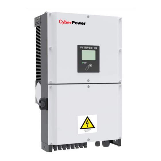
Page 9: Product Description
3. Product Description 3.1 CPS Mini Central series overview Position Description Position Description RS485 AC Plug DC Switch Heat sink Type label Wiring box Warning Label PV input terminals Serial Number RS232 Pront Panel (Item A): LCD & Symbol Description Explanation Knock symbol Indicates for display operation. -
Page 10: Size And Weight
3.2 Size and weight Fig3.4 Fig3.5 A(mm) B(mm) C(mm) Weight(kg) CPSPV30000TL3-S CPSPV33000TL3-S CPSPV40000TL3-S 3.3 Type label The type labels provide a unique identification of the inverter (The type of product, Device-specific characteristics, Certificates and approvals). The type labels are on the right-hand side of the enclosure. -
Page 11: Specification Of Cyberpower Mini Central Series
3.4 Specification of CyberPower Mini Central Series CPSPV30000ETL-WB CPSPV33000ETL-WB CPSPV40000ETL-WB Solar input (DC) Maximum input voltage 1000V Input MPPT voltage range 450 ~ 800V 450V ~ 800V 540 ~ 800V Input operation voltage range 200 ~ 1000 V Maximum input current... - Page 12 CPSPV30000ETL-WB CPSPV33000ETL-WB CPSPV40000ETL-WB Interface Communication RS232, RS485 Display LED & LCD EN 62109-1/-2 EN61000-6-2/EN61000-6-3/EN61000-3-11/EN61000-3-12 Standard VDE0126-1-1:2013 UTE-C-15-712 VFR2014 Protection DC Switch DC Reverse Polarity Protection PV String Fuse DC Surge Protection Yes (Type II) AC Surge Protection Yes (Type II)
-
Page 13: Transportation
If there are lots of inverters need to be stored, the maximum layers for original carton is four. After long term storage, local installer or service department of CyberPower should perform a comprehensive test before installation. 3.7 The advantage of the CPS Mini Central inverters The features of CPS Mini Central series inverter are below: ... -
Page 14: Unpacking
4. Unpacking Before opening the packing box of CPS Mini Central inverters, please note that whether there are any visible external damages. Once open the packing box, please check the delivery for completeness and for any visible external damages of the inverter. If there are anything damaged or missing, please contact your dealer. -
Page 15: Installation
5. Installation 5.1 Safety instruction Danger to life due to fire or explosion Despite careful construction, electrical devices can cause fires. Do not install the inverter on easily flammable materials and where flammable materials are stored. Risk of burns due to hot enclosure parts Mount the inverter in such a way that it cannot be touched unintentionally. -
Page 16: Selecting The Installation Location
5.2 Selecting the Installation Location This is guidance for installer to choose a suitable installation location, to avoid damage to device and operators, The wall selected to install the inverter must be strong and firm enough to support and bear the weight of the inverter for a long period time. - Page 17 Fig.5.2 Required Clearances). Fig5.2 Do not install the inverter near television antenna or any other antennas and antenna cables. Do not install the inverter in living area, noise might affect daily life. For security reasons, don’t install the inverter in place where the children can reach. User Manual 16 / 44 CPS Mini Central series...
-
Page 18: Installation Guide
5.3 Installation guide Step 1:Mounting the Bracket In order to avoid electrical shock or other injury, make sure there is no electrical conduit buried in the wall before drilling holes. To mount the inverter on the wall, we should mount the bracket to the wall firmly first of all. Fig5.3 ... - Page 19 Always checking mounting bracket is really firmly and solid mounted on the wall. Falling equipment can cause fatal injury. After the bracket is firmly mounted on the wall, then mount the inverter on the bracket. Lift up the CPS Mini Central a little higher than bracket with balance. ...
- Page 20 Step 3:Installation layout Avoid exposing inverter to direct sunlight, rain or snow to extend the inverter service life despite the IP65 protection degree. Exposure to the sunlight may cause additional internal heating which will cause power derating. Fig5.8 Fig5.8 User Manual 19 / 44 CPS Mini Central series...
-
Page 21: Electric Connection
6. Electric connection 6.1 Structure of the wiring box Internal layout of the wire box shown as below: Fig 6.1 Location Description Location Description DC switch DC SPD & AC SPD fuse AC terminal block DC terminal AC waterproof plug internal FAN Interface in the wire box shown as below: Location... -
Page 22: Ac Connection
Measure the public grid voltage and frequency Note: Nominal 3-Phase line to line voltage is 400Vac for model CPSPV30000ETL-WB ~ CPSPV 40000ETL-WB Open the DC Switch between the PV inverter and utility Specification of AC breaker: CPSPV30000ETL-WB: 63A/400V... - Page 23 Step 1:Open the wiring box of the CPS Mini Central series inverters Fig 6.3 Step 2:Feed the conductors through the rubber grommet into the wire box. Step 3:Pull the conductors back slightly so as to seal the rubber grommet Step 4:The AC side terminals of the inverter are like the following figure, it is clear to confirm that ‘R, S, T’...
-
Page 24: Dc Connection
DC connection Danger to life due to hazards voltages! Before connecting the PV array, ensure that the DC switch and AC breaker are disconnect from the inverter. NEVER connect or disconnect the DC connectors under load. Improper operation during the wiring process can cause fatal injury to operator or unrecoverable damage to the inverter. - Page 25 Fig 6.5 Max. current of each MPPT: Type Max. current of Each MPPT CPSPV30000ETL-WB 34A/34A CPSPV33000ETL-WB 38A/38A CPSPV40000ETL-WB 38A/38A Cable requirements for each string: Recommended Compatible Model Cross-Section Area Cross-Section Area (mm²) (mm²) CPSPV30000ETL-WB CPSPV33000ETL-WB CPSPV40000ETL-WB User Manual 24 / 44...
-
Page 26: Pv Sw Selection
6.4 PV SW Selection Please refer to about the dipswitch described at Fig 6.2 in section 6.1. The configure of 2-bit dipswitch shown as below, Fig 6.6 Function STATE OF SWITCH DIAGRAM MPPT MPPT (Default) MPPT A only MPPT B only Parallel mode Note the mode only to use inverter with DC source in Lab. -
Page 27: Start-Up And Shut Down The Inverter
7. Start-Up and Shut down the inverter Make sure the inverter has connected DC and AC conductor cables correctly according to the wiring diagram of section 6.2 6.3. & Always make sure the maximum open circuit voltage (Voc) of each PV string is less than 1000VDC. -
Page 28: Shut Down The Inverter
7.2 Shut down the Inverter Turn off the DC switch of the inverter. The LCD text line's information display as below: Fig 7.4 The LED will turn to red In this state, it is working in standby mode, isolated from the DC power ... -
Page 29: Commissioning
8. Commissioning 8.1 Check before commissioning Confirm the inverter is firmly installed again. Install location is suitable for operation and maintenance. Good air flow condition. The inverter is connected properly with its accessories. Cables are well protected from mechanical damage. ... - Page 30 inverter consumes power from PV panel to monitor the internal system. Fault Mode The internal intelligent controller can continuously monitor and adjust the system state. If inverter finds any unexpected conditions such as system fault and inverter fault, the fault information will be displayed on the LCD.
-
Page 31: Display Setting
9. Display setting LCD display LCD screen provide information about the working state of the inverter, historical generating capacity. To operate with the display, one require to knock near the “KNOCK” Icon by hand or tools. KNOCK Icon Fig 9.1 Positon Details Text line for displaying an event... -
Page 32: Led Display
9.2 LED display The LED represents the status of the inverter. LED color /status Inverter status Green/constant Operation Green/flashing countdown for 60s ,standby mode Red/constant Fault– contact installer Standby module Red/flashing Fans Fault-- contact installer Software update Fig 9.2 9.3 Inverter information. -
Page 33: Display Operation
9.4 Display Operation Knock type and definition The inverter can support four kinds of knock: single knock, double knock, thrice knock, four knock . Each kind of knock has different function. The Text line can be used for setting language, models, communication address, string information, time and Date. Before start to set relative parameter, you have to input the setting password. - Page 34 String information Singe Knock on the enclosure until the text line cycles to the “String Info”. Refer to Fig 9.5. Double knock to access the string information shown as Fig 9.6. Single knock to quit. Fig 9.5 Fig 9.6 Once string fault happened, the fault will be shown after software version one before each string information in turns.
- Page 35 Fig 9.8 Once PID fault happened, the fault will be shown after software version before each PID information in turns. Single knock to quit; the inquiry. Following situation is the fault status that might happen. Indicate which strings are reverse connected. For exmaple,”PV12 Reverse”...
- Page 36 Setting language Single knock on the enclosure until the text line cycles shown “Set language”. Refer to Fig 9.9. Double knock to start to edit the Language shown as Fig 9.10. You can choose the language by single knocking; the language includes English, Dutch, Spanish, French, and Italian.
- Page 37 Setting date and time Single knock on the enclosure until the text line cycles to the time refer to Fig 9.16. Double knock to start edit the year "2012", and the two lower number "12" will flash, then single knock to change it. Refer Fig 9.17. Double knock to edit the month "01", and it will flash, then single knock to change it.
- Page 38 Query the energy trend curve. Thrice know under homepage will switch the graphic curve on LCD to shown daily , weekly, monthly and yearly energy. The graph shows hour generation energy in recent 16 hours and the maximum hour energy among them. The graph shows daily generation energy in recent 7 days and the maximum daily energy among them.
-
Page 39: Communication
10.1 Using ‘Solar Power Setup_3P’ to Update firmware & monitor inverter About the software -Solar Power Setup_3P , please download from CyberPower official website. For more detail information about firmware upgrade, please refer to service manual or contact with CyberPower System, Inc. -
Page 40: Rs485 Cable Connection
Monitor the inverters through RS485 interface with “CPS Data Logger” for cloud application. Fig 10.3 CPS Mini Central series inverters are compatible with Solar-Log 200/500/1000. Fig 10.4 CPS Mini Central series inverters are compatible with “Meteocontrol WEB’log” series. Fig10.5 10.3 RS485 cable connection... - Page 41 Fig 10.6 Step 4:Pull the conductors back slightly so as to seal the rubber grommet ※No matter you connect one or more inverters, the last inverter you must install the RS485 terminal resistor parking as “ON” state refer to Fig 10.7 Fig 10.8.
-
Page 42: Maintenance And Cleaning
11. Maintenance and Cleaning Once the output power is derating because of too high warming, some tips can help you solve such problems: The air grills or cooling fans are clogged. To clean the air grills and cooling fans please refer to 11.1 Cleaning Fans and Grills. -
Page 43: Exchange Fan
Fig11.2 Step 4: Take away the fans from the cover and clean them thoroughly. Fig11.3 Step 5: When finishing cleaning, put back the fans in reverse order. 11.2 Exchange Fan Sometimes the heat dissipation error occurred because the cooling fans failed, under such situation, you need to exchange the cooling fans. - Page 44 Disconnect the AC terminal. Step 2: Open the wiring box carefully. Fig11.4 Step 3: Check the broken fuse and exchange a new. Fig11.5 Step 4: Close the wire box. User Manual 43 / 44 CPS Mini Central series...
-
Page 45: Trouble Shooting
StrFuseOpen Warning Fuse is damage Check the fuses Note 1: The CyberPower Mini central have three fans (one internal and two external). Internal (FAN 3) External A (FAN 1) External B (FAN 2) LCD Show WARNING: FAN 3... -
Page 46: Certificates
IEC 62109-1 -2, VDE0126-1-1, EN50438, IEC61727& IEC62116,VFR 2014, CE & 14. Contact If you have technical problems concerning our products, contact your installer or CyberPower. During inquiring, please provide below information: 1. Inverter type 2. Modules information 3. Communication method 4. - Page 47 E-mail: service@cyberpower.com User Manual 46 / 44 CPS Mini Central series...