Table of Contents
Advertisement
Quick Links
Advertisement
Table of Contents

Related Manuals for CyberPower CPSHB300ETR


Summary of Contents for CyberPower CPSHB300ETR
- Page 1 User’s Manual CPSHB300ETR Cyber Power Systems, Inc. www.cyberpower.com...
-
Page 3: Table Of Contents
Contents 1 Information on this Manual ......................1 1.1 Validity ..........................1 1.2 Target Group ........................1 1.3 Symbols Used ........................1 2 Safety ............................2 2.1 Intended Use ........................2 2.2 Safety Precautions ....................... 2 2.3 Assembly Warnings ......................3 2.4 Electrical Connection Warnings .................... - Page 4 9 Decommissioning ........................23 9.1 Dismantling the Inverter ....................23 9.2 Packing the Inverter ......................23 9.3 Disposing of the Inverter ....................23 10 Specification ..........................24 10.1 Specification of CPSHB300ETR ..................24 10.2 Torque Values ........................25 11 Contacts ..........................26...
- Page 5 Table of Figures Fig. 2-1 Energy storage system ........................ 2 Fig. 3-1 Layout of CPSHB300ETR ......................6 Fig. 3-2 Dimensions of CPSHB300ETR ...................... 7 Fig. 4-1 Components included in the scope of deliver ................8 Fig. 5-1 Permitted and prohibited installation positions ................ 10 Fig.
- Page 6 Table of Figures Table 6-1 Charge current setting ......................15 Table 6-2 LEDs indicators for On Grid operation .................. 16 Table 6-3 LEDs indicators for Off Grid operation .................. 17 Table 10-1 Specification ........................24 Table 10-2 Torque values ........................25...
-
Page 7: Information On This Manual
1.2 Target Group This manual is most suitable for users who have basic knowledge around electricity and electrical devices. Note: CyberPower Systems, Inc. will not inform users for any changes taken place within this guide. 1.3 Symbols Used The following types of safety instructions and general information appear within this document:... -
Page 8: Safety
The CPS hybrid series is designed and tested according to international safety requirements; however, certain safety precautions must be observed when installing and operating this inverter. Read and follow all instructions, cautions and warnings in this installation manual. User Manual Hybrid CPSHB300ETR... -
Page 9: Assembly Warnings
Grounding the PV modules: Comply with the local requirements for grounding the PV modules and the PV generator. CyberPower recommends connecting the generator frame and other electrically conductive surfaces in a manner which ensures continuous conduction and ground these in order to have optimal protection of the system and personnel. -
Page 10: Electrical Connection Warnings
(e.g. when sensitive equipment is located at the setup location or when the setup location is near radio or television receivers).In this case, the operator is obliged to take proper action to rectify the situation. User Manual Hybrid CPSHB300ETR... -
Page 11: Symbols On The Inverter
D Don’t touch d during eration. on’t dispose of the produ uct together with the ho ousehold wa ste. In cordance wit th the applic cable dispos al regulation ns for electro onic waste. User Manual Hybrid d CPSHB300ETR... -
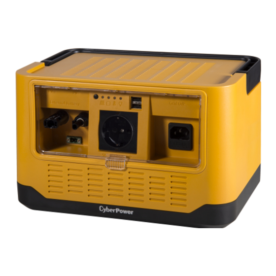
Page 12: Product Description
PV Input Connectors External Battery Connector AC-out Power Outlet AC-in Power Outlet / GRID Tool for Removing PV Connectors 3.2 Size and Weight The dimensions of CPSHB300ETR as Fig. 3-2, the weight is 9kg includes batteries. User Manual Hybrid CPSHB300ETR... -
Page 13: Transportation
USB, pleas keep lig ght or no pow wer from AC C-Out outlet during USB charging op eration. User Manual Hybrid d CPSHB300ETR... -
Page 14: Unpacking
AC C connection User manual & W Warranty Card Even though pac ckaging is m ade to be d urable, plea ase treat it g gently and avoid d tossing it ar round. User Manual Hybrid d CPSHB300ETR... -
Page 15: Installation
The ambient temperature of the inverter should be -10℃~+50℃. The installation location must be freely and safely to get at all times. Vertically installation only. Never install in horizontal positions, and avoid forward and sideways tilting; (observe drawings below) User Manual Hybrid CPSHB300ETR... -
Page 16: Electrical Connections
Fig. 5-1 Permitted a nd prohibite ed installatio on positions 10) No otice the mi nimum clea arances of th he inverter. . (Refer to 3 3.3 Dimensio ons and Fig g.5.2 quired Clear rances). >20cm g. 5-2 Clea arance space e for installat tion 11) Do... -
Page 17: Wiring External Battery Input
Loose the screw of battery connector by screwdriver and pull out the connector. Tight connector screws after you insert battery-wires to lock them into place. An AWG14 wire type is recommended. Place the battery connector back to the inverter and tight it into place. User Manual Hybrid CPSHB300ETR... -
Page 18: Fig. 5-4 Connect Pv Connectors To Inverter
Fig. 5-4 Location of extended battery connector User Manual Hybrid CPSHB300ETR... -
Page 19: Wiring Ac Output
5.3.4 Wir ring AC Ou utput Conditions fo or the AC Con nnection Measure th e grid’s volt tage and fre equency. It should be: (Voltage: 22 20~240VAC single-phase e; Frequenc 50Hz/60Hz) e transpare ent cover an nd plug in t the AC pow wer cord, the e other end... -
Page 20: Operation Modes
PV >27V V and <50V ug in load t o inverter s standalone o output, inve erter will fe ed-in the re esidual pow wer to Grid t lance the po ower consum mption of lo oad (If the re esidual pow er is more t... -
Page 21: Charge Current Setting
Shutdown Mode Inverter aut tomatically s stop running g during no PV power a nd low batte ery. In shutd down mode the inverte take no pow wer from pa anel and bat ttery. If Grid d is availabl e, the inner r charger wo ould continu uously charg... -
Page 22: Leds Indicators
Orange Orange Orange Orange ange Orange Procedure fo or confirmin ng charge cur rrent setting g and exiting g setting mod wants. P on 3s late When the c harge curren nt setting is changed to o what user... - Page 23 Operat ting normally y with battery y <25% and u under Red with chargin Slowly flashing Operat ting normally y with failed o or no battery pends on Bypass The l oad powe r is fully status of Operation supplie...
- Page 24 <22V if Pout <30W (*A) -> Color: depend on the remaining capacity. (*B) -> Flashing frequency: charging is slow, discharging is fast. (*C) -> If Off-Grid operation transfers from On-Grid mode and Grid is abnormal. User Manual Hybrid CPSHB300ETR...
-
Page 25: Start-Up And Shut-Down The Inverter
2. Turn on the DC switch or connect PV connectors, press and hold the button of inverter until Off-Grid LED is green (release the button immediately when that LED is green). 3. Inverter will start Off-Grid operation if the input voltage is higher than 27V or battery voltage is User Manual Hybrid CPSHB300ETR... -
Page 26: Shut-Down The Inverter
1. If inverter is operating, press and hold the button until all LEDs are red, it takes around 3 seconds. 2. Disconnect the AC/Grid power cord. 3. Disconnect all PV connectors. 4. When all LEDs are OFF, the inverter will totally shutdown. User Manual Hybrid CPSHB300ETR... -
Page 27: Maintenance
Turn the batteries to bring up their connectors; (Fig. 8-1c & d). Fig. 8-1 Procedure of replacing batteries Disconnect the 2 batteries from inverter and replace them with new ones. Connect the new batteries to inverter, notice the polarity! Assemble the inverter in reverse order. User Manual Hybrid CPSHB300ETR... -
Page 28: Replace The Fuse
Pull out the fuse holder underneath the AC/Grid socket. Replace the broken fuse with new one. Note the rating must be 6.3A/250V P Place the fuse assembly back into the AC/Grid socket. Fig. 8-2 Grid O/P fuse replacement User Manual Hybrid CPSHB300ETR... -
Page 29: Decommissioning
9 Deco ommis ssionin 9.1 Dism antling th he Invert nger of burn injuries due e to hot encl osure parts it 20 minut tes before d disassemblin ng until the e housing h as cooled sconnect the e inverter as described in n section 7. -
Page 30: Specification
Specification 10.1 Specification of CPSHB300ETR Table 10-1 Specification CPSHB300ETR PV Input Max. input power 310W Absolute max. input voltage 50Vdc Full power voltage range 34-38Vdc Operating voltage range 28-48Vdc Rated input voltage 36Vdc Max. input current 9Adc MPP Tracker Voltage: <2% Measurements deviation Current: <2%... -
Page 31: Torque Values
-20-40℃ Storage temperature Relative humidity 0-95% Operating elevation 0-2000m (0-6666ft) Cooling Natural convection Mechanical Dimension (W*H*D, mm) 292*186*202 Weight Package dimension 380*305*290 (W*H*D, mm) 10.2 Torque Values Table 10-2 Torque values Battery cover screws 10kgf.cm (0.98N.m) User Manual Hybrid CPSHB300ETR... -
Page 32: Contacts
11 Contacts If you have technical problems concerning our products, contact your installer or CyberPower. During inquiring, please provide below information: Model Name Serial Number Detailed Error Description Cyber Power Systems, Inc. www.cyberpower.com User Manual Hybrid CPSHB300ETR... - Page 33 Note...
- Page 34 Note...
- Page 36 K01-0000591-00...