
Related Manuals for CyberPower CPSPV8000ETL-S


Summary of Contents for CyberPower CPSPV8000ETL-S
- Page 1 CPSPV7000ETL-S CPSPV8000ETL-S CPSPV9000ETL-S CPSPV10000ETL-S CPSPV11000ETL-S CPSPV12000ETL-S CPSPV15000ETL-S User’s Manual CyberPower Systems Inc. www.cyberpower.com Index...
-
Page 2: Table Of Contents
CONTENTS INFORMATION ON THIS MANUAL ..................3 ..................................3 ALIDITY ................................ 3 ARGET ROUND ................................4 YMBOLS SAFETY ........................... 5 ................................5 NTENDED ..............................6 AFETY RECAUTIONS ..............................6 SSEMBLY ARNINGS ..........................6 LECTRICAL ONNECTION ARNINGS ..............................7 PERATION ARNINGS PRODUCT DESCRIPTION ...................... - Page 3 ............................. 33 NVERTER INFORMATION ..............................34 ISPLAY PERATION COMMUNICATION ......................38 10.1 ‘S _3P’ & ..............38 SING OLAR OWER ETUP PDATE FIRMWARE MONITOR INVERTER 10.2 ............................39 ONITOR THE INVERTERS 10.3 RS485 ............................40 CABLE CONNECTION TROUBLE SHOOTING ......................41 CERTIFICATES ........................
-
Page 4: Information On This Manual
Store this manual where accessible at all times. 1.2 Target Ground This manual is for qualified persons such as PV system installers or electricians. Notes: For possible changes in this manual, CyberPower Systems, Inc. accepts no responsibilities to inform the users User Manual... -
Page 5: Symbols Used
1.3 Symbols Used The following types of safety instructions and general information appear in this document as described below: Symbol description Read the manual DANGER indicates a hazardous situation which, if not avoided, will result in death or serious injury. WARNING indicates a hazardous situation which, if not avoided, could result in death or serious injury. -
Page 6: Safety
If PV modules of the PV system require POSITIVE or NEGATIVE grounding, , please contact CyberPower Systems, Inc. for technical support before installation. User Manual... -
Page 7: Safety Precautions
Grounding the PV modules: Comply with the local requirements for grounding the PV modules frame and the PV generator. CyberPower strongly recommends grounding the generator frame in order to have optimal earth protection to PV generating system and personnel. -
Page 8: Operation Warnings
responsible for damage caused by incorrect operation, installation, wiring, transport, etc. The CPS Mini Central series is to be used solely to feed solar energy converted photovoltaic into the public grid. The inverter is suitable for mounting both indoors and outdoors. ... - Page 9 might be happened despite inverter had complied emission limit. In this case, the operator is obliged to take proper action to improve the situation. 2.6 Symbols on the inverter Symbol Explanation Refer to operation instruction Caution, risk of electrical shock Caution, hot surface Earth (ground) terminal Caution, risk of electrical shock.
-
Page 10: Product Description
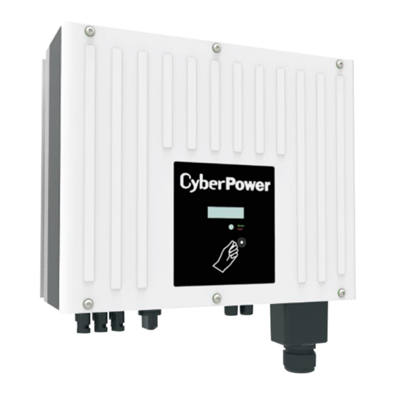
3. Product Description 3.1 CPS Mini Central series overview Position Description Position Description DC Switch PV input terminals RS232 Serial Number AC Output Heat sink Type label RS485 Pront Panel (Item A): LCD & Symbol Description Explanation Knock symbol Indicates for display operation. Constant Green Operation Flashing Green... -
Page 11: Size And Weight
3.2 Size and weight Fig3.4 A(mm) B(mm) C(mm) D(mm) Weight(kg) CPSPV7000ETL-S CPSPV8000ETL-S CPSPV9000ETL-S CPSPV10000ETL-S CPSPV11000ETL-S CPSPV12000ETL-S 23.5 CPSPV15000ETL-S User Manual 10 / 43 CPS Mini Central series... -
Page 12: Type Label
3.3 Type label The type labels provide a unique identification of the inverter (The type of product, Device-specific characteristics, Certificates and approvals). The type labels are on the right-hand side of the enclosure. User Manual 11 / 43 CPS Mini Central series... -
Page 13: Specification Of Cyberpower Mini Central Series
3.4 Specification of CyberPower Mini Central Series CPSPV7000ETL-S CPSPV8000ETL-S CPSPV9000ETL-S CPSPV10000ETL-S CPSPV11000ETL-S Solar input (DC) Maximum input voltage 1000V Input MPPT voltage range 320 ~ 850V 360 ~ 850V 400 ~ 850V 450 ~ 850V 450 ~ 850V Input operation voltage range... - Page 14 CPSPV7000ETL-S CPSPV8000ETL-S CPSPV9000ETL-S CPSPV10000ETL-S CPSPV11000ETL-S Interface Communication RS232, RS485 Display LED & LCD EN 62109-1/-2 EN61000-6-2/EN61000-6-3/EN61000-3-11/EN61000-3-12 Standard VDE0126-1-1:2013 UTE-C-15-712:2013 VFR2014 Protection DC Switch DC Reverse Polarity Protection RCMU General Data Dimensions (H x W x D) (mm) 480 x 440 x200mm...
- Page 15 CPSPV12000ETL-S CPSPV15000ETL-S Solar input (DC) Maximum input voltage 1000V Input MPPT voltage range 480 ~ 850V 520 ~ 850V Input operation voltage range 160 ~ 1000 V Maximum input current 20A/10A 20A/10A Max Recomanded PV power 14400W 18000W Efficiency MPP tracker 99.5% 99.5% Number of MPPT trackers...
- Page 16 CPSPV12000ETL-S CPSPV15000ETL-S Interface Communication RS232, RS485 Display LED & LCD EN 62109-1/-2 EN61000-6-2/EN61000-6-3/EN61000-3-11/EN61000-3-12 Standard VDE0126-1-1:2013 UTE-C-15-712:2013 VFR2014 Protection DC Switch DC Reverse Polarity Protection RCMU General Data Dimensions (H x W x D) (mm) 480 x 440 x200mm Weight (kg) 23.5 kg Cooling method Natural...
-
Page 17: Transportation
If there are lots of inverters need to be stored, the maximum layers for original carton is four. After long term storage, local installer or service department of CyberPower should perform a comprehensive test before installation. 3.7 The advantage of the CPS Mini Central inverters The features of CPS Mini Central series inverter are below: ... -
Page 18: Unpacking
4. Unpacking Before opening the packing box of CPS Mini Central inverters, please note that whether there are any visible external damages. Once open the packing box, please check the delivery for completeness and for any visible external damages of the inverter. If there are anything damaged or missing, please contact your dealer. -
Page 19: Installation
5. Installation 5.1 Safety instruction Danger to life due to fire or explosion Despite careful construction, electrical devices can cause fires. Do not install the inverter on easily flammable materials and where flammable materials are stored. Risk of burns due to hot enclosure parts Mount the inverter in such a way that it cannot be touched unintentionally. -
Page 20: Selecting The Installation Location
5.2 Selecting the Installation Location This is guidance for installer to choose a suitable installation location, to avoid damage to device and operators, The wall selected to install the inverter must be strong and firm enough to support and bear the weight of the inverter for a long period time. - Page 21 Notice when more than one inverters be installed ,the minimum clearances between inverters should be large than 300mm to assure cooling works well. (Refer Fig.5.2 Required Clearances). Fig5.2 Do not install the inverter near television antenna or any other antennas and antenna cables.
-
Page 22: Installation Guide
5.3 Installation guide Step 1:Mounting Expansion Bolt In order to avoid electrical shock or other injury, make sure there is no electrical conduit buried in the wall before drilling holes. To mount the inverter on the wall, we should mount expansion bolt to the wall firmly first. ... - Page 23 Fig5.5 Fig 5.4. Fig 5.5. User Manual 22 / 43 CPS Mini Central series...
- Page 24 Step 3:Installation layout Avoid exposing inverter to direct sunlight, rain or snow to extend the inverter service life despite the IP65 protection degree. Exposure to the sunlight may cause additional internal heating which will cause power derating. Fig5.6 Fig5.7 User Manual 23 / 43 CPS Mini Central series...
-
Page 25: Electric Connection
Measure the public grid voltage and frequency (Voltage: 400Vac; Frequency: 50Hz/60Hz; in 3-Phase); Open the breaker between the On-grid Solar Power Generating System and utility; Specification of AC breaker: CPSPV70000ETL-S: 16A/400V CPSPV8000ETL-S : 20A/400V CPSPV9000ETL-S: 20A/400V CPSPV10000ETL-S: 25A/400V CPSPV11000ETL-S: 25A/400V... - Page 26 AC Power Cable requirements: Model Diameter(mm) Area(mm²) Available wire gauge (AWG) CPSPV7000ETL-S 2.05~4.11 4~16 12~6 CPSPV8000ETL-S 2.05~4.11 4~16 12~6 CPSPV9000ETL-S 2.05~4.11 4~16 12~6 CPSPV10000ETL-S 2.05~4.11 4~16 12~6 CPSPV11000ETL-S 2.05~4.11 4~16 12~6 CPSPV12000ETL-S 2.05~4.11 4~16 12~6 CPSPV15000ETL-S 2.05~4.11 4~16 12~6 Please do not use single-core wire cable.
-
Page 27: Dc Connection
6.2 DC connection Danger to life due to hazards voltages! Before connecting the PV array, ensure that the DC switch and AC breaker are disconnect from the inverter. NEVER connect or disconnect the DC connectors under load. Improper operation during the wiring process can cause fatal injury to operator or unrecoverable damage to the inverter. -
Page 28: Grounding
Fig 6.2 6.3 Grounding AC Grounding The CPS Mini Central On-grid Solar Power Generating System must be connected to the AC grounding conductor of the power distribution grid via the ground terminal (PE). PV Grounding The grounding conductor in the framework of the PV array must be connected to the PV grounding conductor and the DC grounding conductor. -
Page 29: Grid Type
6.4 Grid Type Common grid type Based on the local GRID standards, it may select different connection types. In the following you will find an overview of the most common type of grid structure. User Manual 28 / 43 CPS Mini Central series... -
Page 30: Start-Up And Shut Down The Inverter
7. Start-Up and Shut down the inverter Make sure the inverter has connected DC and AC conductor cables correctly according to the wiring diagram of section 6.1 6.2. & Always make sure the maximum open circuit voltage (Voc) of each PV string is less than 1000VDC. -
Page 31: Shut Down The Inverter
7.2 Shut down the Inverter Turn off the DC switch of the inverter. The LCD text line's information display as below: Fig 7.4 The LED will turn to red In this state, it is working in standby mode, isolated from the DC power Fully shut down the inverter by turning off the AC grid until the LCD and the LED are powered off. -
Page 32: Commissioning
8. Commissioning 8.1 Check before commissioning Confirm the inverter is firmly installed again. Install location is suitable for operation and maintenance. Good air flow condition. The inverter is connected properly with its accessories. Cables are well protected from mechanical damage. ... - Page 33 Fault Mode The internal intelligent controller can continuously monitor and adjust the system state. If inverter finds any unexpected conditions such as system fault and inverter fault, the fault information will be displayed on the LCD. In fault mode the LED turns red. ...
-
Page 34: Display Setting
9. Display setting LCD screen provide information about the working state of the inverter. To operate with the display, one require to knock near the “KNOCK” Icon by hand or tools 9.1 LED display The LED represents the status of the inverter. LED color /status Inverter status Green/constant... -
Page 35: Display Operation
9.3 Display Operation Knock type and definition The inverter can support four kinds of knock: single knock, double knock, thrice knock, four knock . Each kind of knock has different function. The Text line can be used for setting language, models, communication address, string information, time and Date. Before start to set relative parameter, you have to input the setting password. - Page 36 Input setting password Single knock on the enclosure lid single until the text line shown “setting ...”. Refer to Fig 9.7. Then double knock to enter the setting page, the inverter requests password shown as Fig 9.8. Double knock on the enclosure to start edit the number text “000”. 1 number will start to blink.
- Page 37 Setting RS485 com address Single knock on the enclosure until the text line cycles show “Com Address”. Refer to Fig 9.12. Double knock the enclosure to start edit the low digits in number text "001". You can to change it with more single knock on the enclosure shown as Fig 9.13. If you want to set the address with higher digits, double knock to let the higher number text “020”...
- Page 38 Fig 9.18 Fig9.19 Fig9.20 Fig9.21 User Manual 37 / 43 CPS Mini Central series...
-
Page 39: Communication
10.1 Using ‘Solar Power Setup_3P’ to Update firmware & monitor inverter About the software -Solar Power Setup_3P , please download from CyberPower official website. For more detail information about firmware upgrade, please refer to service manual or contact with CyberPower System, Inc. -
Page 40: Monitor The Inverters
The inverter provides RS232/RS485 interface to communicate with remote PC or logger. User can monitor the inverter state via the following types of communication systems. For more detail information, please contact with CyberPower Systems, Inc. Monitor the inverters through RS485 interface with software “Solar Power Monitoring”. -
Page 41: Rs485 Cable Connection
10.3 RS485 cable connection RS485 cable connection Pin 1 TR-(B) Pin 2 Shielding layer or no connection Pin 3 TR+(A) Definitions of RS485 PLUG (standard) as follows: Pin 1 TR-(B) Pin 2 Shielding layer or no connection Pin 3 TR+(A) Step 1 : Please loosen four screws, take down the RS485 waterproof cover from inverter. -
Page 42: Trouble Shooting
PV Cable Error 126 Residual I High Residual current is above limit . Please check the PV and AC Cable. Restart inverter, if problem still exist, Contact CyberPower. Error 127 Output high DCI Contact CyberPower. Error 128 PV Voltage High PV input voltage is above 1000V . -
Page 43: Certificates
CPSPV15000ETL-S IEC 62109-1 -2, VDE0126-1-1, EN50438, VFR 2014, CE & 13. Contact If you have technical problems concerning our products, contact your installer or CyberPower. During inquiring, please provide below information: 1. Inverter type 2. Modules information 3. Communication method 4.