
Related Manuals for CyberPower CPSPV3600ETL-IN SLV


Summary of Contents for CyberPower CPSPV3600ETL-IN SLV
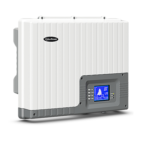
- Page 1 User’s Manual CPSPV3600ETL-IN SLV CPSPV3000ETL-IN SLV CPSPV2000ETL-IN SLV CyberPower Systems Inc.
- Page 2 www.cpsww.com...
-
Page 3: Important Safety Instructions
IMPORTANT SAFETY INSTRUCTIONS Save These Instructions! This manual contains important constructions that shall be followed during the installation and maintenance of the CyberPower On-grid Solar Power Generating System. CAUTION! Before installation and using the On-grid Solar Power CAUTION! Cautions identify conditions or practices that Generating System, read all instructions and cautionary markings could result in damage to the unit or other equipment. - Page 4 IMPORTANT SAFETY INSTRUCTIONS Photovoltaic Vdc: Volts DC PWM: Pulse Width Modulation Voltage at Maximum power Vac: Volts AC Open Circuit Voltage Copyright © 2012 CyberPower Systems, Inc.
- Page 5 UNPACKING 2) Stainless wall mount bracket 1) CPSPV2000ETL、CPSPV3000ETL or CPSPV3600ETL 3) User’s manual 4) Warranty card module 5) Self-tapping screws: M6*20L(5) Copyright © 2012 CyberPower Systems, Inc.
-
Page 6: Installation
CyperPower On-grid Solar Power Generating System the specified sections for more information. On-grid Solar Power Generating System Location? The CyberPower On-grid Solar Power Generating System is PV Array Requirements? designed to convert solar electric (photovoltaic or PV) power into Grounding Requirements? - Page 7 All electrical terminations should be fully tightened, secured, CPSPV3600ETL model, the On-grid Solar Power Generating and strain relieved as appropriate. System will continue to operate, but it will regulate the PV voltage to 250Vdc for CPSPV3600ETL model. Because the array Copyright © 2012 CyberPower Systems, Inc.
- Page 8 This section includes the following topic: voltage (Vdc) Wiring Do not exceed the maximum array short circuit current The wires to AC terminal: rating marked on the On-grid Solar Power Generating Acceptable wire size: System. Copyright © 2012 CyberPower Systems, Inc.
- Page 9 AC Circuit breaker This breaker must be sized to handle the rated maximum output voltage and current of the On-grid Solar Power Generating System. (Please refer to the On-grid Solar Power Generating System specification) Copyright © 2012 CyberPower Systems, Inc.
- Page 10 If your installation location requires that you drill additional conduit holes into the bracket, ensure that there are no metal shavings left inside the unit. These could cause a short circuit when unit is operating. Copyright © 2012 CyberPower Systems, Inc.
-
Page 11: Standard Feature
E : LED Indicator Light (Green) – Flash: Standby for reconnection / Solid: Operation ○ F : LED Indicator Light (Red) – Warning condition ○ G : LED Indicator Light (Yellow) – Ground fault Rear Panel Feature Copyright © 2012 CyberPower Systems, Inc. - Page 12 4 : M20*1.5 cable glands * 2pcs: For RS-485 communication ○ 5 : M20*1.5 cable gland * 1pcs: For RM card communication ○ 6 : AC connector (male): Connect to the utility output Recommended female type: PWJ-03BFFB-LL8001 (Amphenol) Copyright © 2012 CyberPower Systems, Inc.
-
Page 13: Start-Up Procedure
Switch on the AC circuit for the On-grid Solar Power Generating System The On-grid Solar Power Generating System responds by starting it reconnecting protection timer. Ensure that the On-grid Solar Power Generating System does not produce power before the countdown is over. After completing the Copyright © 2012 CyberPower Systems, Inc. - Page 14 The default voltage, frequency and reconnect delay values are programmed into the unit at time of shipment from the factory. No changes to these settings can be made in the field by the user. Only authorized personnel with utility permission may change these settings. Copyright © 2012 CyberPower Systems, Inc.
-
Page 15: Data Logger
E x i t D a t e & T i m e M a i n M e n u After you select above three items, the display will enter into “Home Page” Copyright © 2012 CyberPower Systems, Inc. - Page 16 In “Main Menu”, select Multi meter, then In “Data Logger”, select Daily Log, then press “Enter” key press “Enter” key 2.3.1 Daily Log: 2.2 Multi meter: In “Data Logger”, select Monthly Log, then press “Enter” 2.3.2 Monthly Log: Copyright © 2012 CyberPower Systems, Inc.
-
Page 17: Device Info
There are over last 100 dated failure reports on the NS protection can be read. In “Main Menu”, select Config, then press “Enter” key 2.5 Config: In “Config”, select Grid Set, then press “Enter” key 2.5.2 Grid Settings: Copyright © 2012 CyberPower Systems, Inc. - Page 18 In “Config”, select Device Info, then press “Enter” key 2.5.4 Device Info: D e v i c e I n f o In “Config”, select Installer Code, then press “Enter” key 2.5.5 Installer Code: Copyright © 2012 CyberPower Systems, Inc.
- Page 19 The settings only can be used by authorized IMPORTANT: personnel with utility permission. The settings only can be used by authorized personnel with utility permission. In “Config”, select RMCard Set, then press “Enter” key Copyright © 2012 CyberPower Systems, Inc.
- Page 20 Temperature sensor 1 low Hardware CT failure Temperature sensor 1 high Hardware AC current OCP Hardware temperature sensor 1 DC input current high (slow) failure DC input current high (fast) Temperature sensor 2 high Copyright © 2012 CyberPower Systems, Inc.
-
Page 21: Technical Specifications
Power factor range 0.8 Leading ~ 0.8 Lagging Nighttime power consumption About 1 Watt Output AC fuse Current limitation and thermal de-rating Output protection Over temperature protection Output detection tolerance Utility voltage deviation < 1% Copyright © 2012 CyberPower Systems, Inc. - Page 22 19.5 Kg 19.5 Kg Gross Weight 21.5 Kg 23 Kg 23 Kg Enclosure rating IP 65 Installation type Wall mount DC connector 1 pairs connectors AC connector Waterproof AC connector CyberPower Systems Inc. www.cpsww.com Copyright © 2012 CyberPower Systems, Inc.
- Page 23 There are special requirements. The On-grid Solar Power Generating System complies with the requirements of the applicable EC guidelines. The On-grid Solar Power Generating System must not be disposed of together with the household waste. Copyright © 2012 CyberPower Systems, Inc.
- Page 24 0.45% 0.2 sec Ground Current (mA) 0.3 sec 0.3 sec 0.3 sec 0.3 sec Insulation 5 sec 5 sec 5 sec 5 sec Islanding Islanding Factor Active Power Reactive Power Frequency de-rating Power slow-up Copyright © 2012 CyberPower Systems, Inc.
- Page 25 Code setting table Reactive power measurement 0,90 0,92 0,94 0,96 0,98 1,00 0,98 0,96 0.94 0.92 0,90 P/Pemax Copyright © 2012 CyberPower Systems, Inc.