Table of Contents
Advertisement
Quick Links
Advertisement
Table of Contents

Related Manuals for CyberPower CPSPV5000ETL


Summary of Contents for CyberPower CPSPV5000ETL
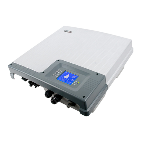
- Page 1 User’s Manual CPSPV5000ETL CPSPV4000ETL CyberPower Systems Inc. www.cpsww.com...
-
Page 2: Important Safety Instructions
IMPORTANT SAFETY INSTRUCTIONS Save These Instructions! This manual contains important constructions that shall be followed during the installation and maintenance of the CyberPower Grid Tie Solar Inverter. CAUTION! Before installation and using the Inverter, read all About This Manual instructions and cautionary markings on the inverter and appropriate This purpose of this Installation &... - Page 3 UNPACKING 2) Stainless wall mount bracket 1) CPSPV5000ETL or CPSPV4000ETL module 3) User’s manual 4) Warranty card 5) Self-tapping screws: M6*30L(5) Copyright © 2012 CyberPower Systems, Inc.
-
Page 4: Installation
Ensure that the inverter is mounted in a location where the ambient configuration. temperature range is -20℃ to +60℃. When the temperature is over For CPSPV5000ETL / CPSPV4000 ETL, only one PV array can be +40℃, the inverter may de-rate power. connected to the inverter. - Page 5 17A) Maximum harvest of solar energy. MPPT window 310~750 Maximum harvest of solar energy. (limit MPPT window 750~900 input max power) Will shut down and may cause damage Shutdown >900 to the inverter. Copyright © 2012 CyberPower Systems, Inc.
-
Page 6: Grounding Requirements
This breaker must be sized to handle the rated maximum output voltage and current of the inverter. (Please refer to the inverter specification) Recommended AC Circuit Breaker: For CPSPV5000ETL: 32 Amps / 250 Vac. For CPSPV4000ETL: 25 Amps / 250 Vac. Copyright © 2012 CyberPower Systems, Inc. -
Page 7: Mounting The Inverter
Step3: Make sure the host of inverter on the incision of into the bracket, ensure that there are no metal shavings left inside the the wall mount bracket unit. These could cause a short circuit when unit is operating. Copyright © 2012 CyberPower Systems, Inc. -
Page 8: Standard Feature
E : LED Indicator Light (Green) – Flash: Standby for reconnection / Solid: Operation ○ F : LED Indicator Light (Red) – Warning condition ○ G : LED Indicator Light (Yellow) – Ground fault Copyright © 2012 CyberPower Systems, Inc. - Page 9 4 : M20*1.5 cable glands * 2pcs: For RS-485 communication ○ 5 : M20*1.5 cable gland * 1pcs: For RM card communication ○ 6 : AC connector (male): Connect to the utility output 96.0314154.3 (Wieland) Recommended female type: Copyright © 2012 CyberPower Systems, Inc.
-
Page 10: Start-Up Procedure
The default voltage, frequency and reconnect delay values are programmed into the unit at time of shipment from the factory. No changes to these settings can be made in the field by the user. Only authorized personnel with utility permission may change these settings. Copyright © 2012 CyberPower Systems, Inc. -
Page 11: Data Logger
E x i t D a t e & T i m e M a i n M e n u After you select above three items, the display will enter into “Home Page” Copyright © 2012 CyberPower Systems, Inc. -
Page 12: Monitoring The Inverter
S a v i n g s 7 0 4 . 7 k W h 3 1 1 . 4 7 E U R D a t a L o g g e r Copyright © 2012 CyberPower Systems, Inc. -
Page 13: Device Info
In “Main Menu”, select Config, then press “Enter” key 2.5 Config: Date Display & Time IMPORTANT: The settings only can be used by authorized personnel with utility permission. Device Grid Info C o n f i g Copyright © 2012 CyberPower Systems, Inc. - Page 14 F i r m w a r e ( R ) V 0 0 . 5 1 D e v i c e I n f o IMPORTANT: The settings only can be used by authorized personnel with utility permission. Copyright © 2012 CyberPower Systems, Inc.
- Page 15 Hardware CT failure Temperature sensor 2 high Hardware AC current OCP Hardware temperature sensor 2 DC input current high (slow) failure DC input current high (fast) Temperature sensor 3 high Hardware temperature sensor 3 Copyright © 2012 CyberPower Systems, Inc.
-
Page 16: Technical Specifications
Adjustable reactive power range 0.8 inductive ~0.8 capacitive Nighttime power consumption < 1 Watt Output AC fuse Current limitation and thermal de-rating Output protection Over temperature protection Output detection tolerance Utility voltage deviation < 1% Copyright © 2012 CyberPower Systems, Inc. - Page 17 L x W x H = 615 x 615 x 380 mm Net Weight 26 Kg Gross Weight 30.5 Kg Enclosure rating IP 65 Installation type Wall mount DC connector 2 pairs of Multi Contact connectors AC connector Waterproof AC connector CyberPower Systems Inc. www.cpsww.com Copyright © 2012 CyberPower Systems, Inc.
- Page 18 Beware of hot surface. Observe enclosed documentation. There are special requirements. The inverter complies with the requirements of the applicable EC guidelines. The inverter must not be disposed of together with the household waste. Copyright © 2012 CyberPower Systems, Inc.
- Page 19 0.45% 0.2 sec Ground Current (mA) 0.3 sec 0.3 sec 0.3 sec 0.3 sec Insulation 5 sec 5 sec 5 sec 5 sec Islanding Islanding Factor Active Power Reactive Power Frequency de-rating Power slow-up Copyright © 2012 CyberPower Systems, Inc.
- Page 20 Code setting table Reactive power measurement 0,90 0,92 0,94 0,96 0,98 1,00 0,98 0,96 0.94 0.92 0,90 P/Pemax Copyright © 2012 CyberPower Systems, Inc.