Furuno DS-60 Operator's Manual
Doppler sonar
Hide thumbs
Also See for DS-60:
- Operator's manual (94 pages) ,
- Installation manual (74 pages) ,
- Brochure & specs (6 pages)
Table of Contents
Advertisement
Quick Links
Advertisement
Chapters
Table of Contents

Related Manuals for Furuno DS-60


Summary of Contents for Furuno DS-60
- Page 1 OPERATOR'S MANUAL DOPPLER SONAR DS-60 Model www.furuno.com...
- Page 2 ・FURUNO Authorized Distributor/Dealer 9-52 Ashihara-cho, Nishinomiya, 662-8580, JAPAN A : MAR 2010 Printed in Japan All rights reserved. G2 : DEC . 13, 2022 Pub. No. OME-72640-G2 (ETMI ) DS-60 0 0 0 1 7 2 3 3 4 1 6...
- Page 3 How to discard a used battery Some FURUNO products have a battery(ies). To see if your product has a battery, see the chapter on Maintenance. If a battery is used, tape the + and - terminals of the battery before disposal to pre- vent fire, heat generation caused by short circuit.
- Page 4 Fire or electrical shock can result if the off the power at the switchboard power remains on. immediately. Contact a FURUNO agent or dealer for advice. Turn off the power at the switchboard if the equipment is emitting smoke or fire.
- Page 5 Remove marine life from the face of the Warning label(s) is(are) attached to the equipment. Do not remove the label(s). If a label is missing or transducer when the ship is dry-docked. damaged, contact a FURUNO agent or dealer about replacement. Marine life can affect sensitivity. Name:...
-
Page 6: Table Of Contents
TABLE OF CONTENTS FOREWORD ........................vi SYSTEM CONFIGURATION ..................viii INTRODUCTION ....................1-1 1.1 Controls........................1-1 1.1.1 Display Unit DS-600..................1-1 1.1.2 Remote Controller RD-501 (option) ............... 1-3 1.1.3 Dimmer Controller RD-502 (option) ............... 1-3 1.2 How to Turn the Power On and Off................1-4 1.3 How to Adjust the Screen Brilliance ................ - Page 7 TABLE OF CONTENTS OTHER OPERATIONS ..................5-1 5.1 How to Set the Displays .....................5-1 5.2 Key Beep On/Off ......................5-4 5.3 How to Adjust Key Dimmer..................5-4 5.4 How to Select Direction Symbol Format..............5-5 5.5 How to Select the Location for the Direction Symbols..........5-6 5.6 Total Distance Run .....................5-7 5.6.1 How to reset total distance run...............5-7...
-
Page 8: Foreword
The DS-60 is a high precision Doppler Sonar designed for use on VLCC, LNG, LPG, container ships, cargo ships, etc. The DS-60 measures speeds relative to ground and water in the fore, stern and transverse directions. This arrangement provides for precision docking of tankers and the like to loading and unloading facilities, as well as safe navigation in narrow channels and straits. - Page 9 FOREWORD Remarks on usage of the DS-60 The DS-60 measures ship’s speed by detecting the Doppler shift frequency of the echo reflected by a watermass (water layer containing plankton and other micro-organisms) located within the measuring area, which is usually about 2 m. In some instances, however, no signal is returned because of too few plankton in the sensing depths.
-
Page 10: System Configuration
SYSTEM CONFIGURATION MAIN DISPLAY UNIT RD-501 RD-502 DS-600 REMOTE DIMMER DISPLAY CONTROLLER CONTROLLER UNIT RD-50 / RD-20 RD-50 / RD-20 SUB DISPLAY UNIT DS-600 (DS-605) / RD-501* RD-502* RD-50 / RD-20 REMOTE DIMMER DISPLAY CONTROLLER CONTROLLER UNIT Max. 5 DISTRIBUTOR UNIT *: Cannot be connected when DS-610 DS-605 Is installed. -
Page 11: Introduction
INTRODUCTION This chapter provides the information necessary to get you started with the system. The display unit has ten keys that respond immediately to your command. When you operate a key, a single beep sounds. If you do not need the beep, you can deactivate the beep from the menu. - Page 12 1. INTRODUCTION Control Function TRKG • Main display unit: Select the tracking mode (water, ground, or auto) for MODE the measurement of ship’s speed. • Sub display unit: Select the ship speed mode between SOG and STW when the tracking mode at the main display is ground tracking. UNIT Select the unit of measurement for speed, depth, distance, current (tide) speed, wind speed, etc.
-
Page 13: Remote Controller Rd-501 (Option)
1. INTRODUCTION 1.1.2 Remote Controller RD-501 (option) DISP UNIT MODE REMOTE CONTROLLER RD - 501 Control Function DISP • Select a display. • Close the menu and return to last-used display. • In multiple data displays, select a data indication to change its unit of mea- surement (with the UNIT key). -
Page 14: How To Turn The Power On And Off
Note: If "NG" appears as the RAM or ROM check result, the equipment stops. Reset the power to try to restore normal operation. If you cannot restore normal operation, contact a FURUNO agent or dealer for instruction. To turn off the power, press the PWR key. -
Page 15: How To Adjust The Screen Brilliance
The default brilliance setting is [9]. If the Remote Display RD-50 (sub display unit) is connected to the display unit of the DS-60 in a daisy chain, their brilliances are mutually adjusted when you adjust the bril- liance from the DS-60. -
Page 16: How To Select A Tracking Mode
1. INTRODUCTION How to Select a Tracking Mode Press the TRKG MODE key (main display unit) or the MODE key (Remote Controller) to select a tracking mode, among ground, water and auto. Select the mode according to the depth and speed. The tracking mode indication, Ground, Water, or (Auto), appears at the top-right corner. -
Page 17: How To Change Units Of Measurement
1. INTRODUCTION How to Change Units of Measurement The UNIT key selects the unit of measurement for current (tide) speed, depth, dis- tance, Doppler SOG and STW, GPS SOG, and wind speed. Single data display Press the UNIT key to select a unit of measurement. Multiple data display 1. -
Page 18: How To Reset The Trip Distance Indication
1. INTRODUCTION How to Reset the Trip Distance Indication You can reset the trip distance indication on the displays that shows the trip distance. Press the ENT key until the trip distance indication shows all zeros. (Trip distance can also be reset from the menu, with [Trip DIST] [RESET].) Trip distance Trip distance, total distance display Trip distance... -
Page 19: How To Select Daytime And Nighttime Displays
1. INTRODUCTION How to Select Daytime and Nighttime Displays The DAY/NT key selects the daytime (black characters on a white background) and nighttime (white characters on a black background) displays alternately, for comfort- able viewing according to the time of day. Daytime Nighttime General Menu Operation... - Page 20 1. INTRODUCTION 3. Select an item from the menu options window then press the ENT key. One of the four types of boxes shown below appears. Follow the related procedure to make your selection. List box 1. Select option with 2.
-
Page 21: Navigation Data Display
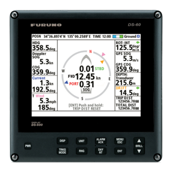
NAVIGATION DATA DISPLAY Navigation Data Display Overview The navigation data display provides comprehensive navigation data (with connection of related sensors) and a 3-axis speed display. When a data is lost, its numerical indi- cation is shown with hyphens; for example, “---.-”. When a data is in error, its unit; for example, “kn,”... -
Page 22: Description Of Indications
2. NAVIGATION DATA DISPLAY 2.1.1 Description of indications Descriptions in clockwise order from top-left corner. Indication Description POSN Latitude and longitude position of your ship, input by a position-fixing equipment (GPS, etc.). Time Time, input by a position-fixing equipment, is available in UTC or local time, selectable from the menu. -
Page 23: How To Set Navigation Data
When the indicator stops moving, it may mean there is a problem indicator with the system (screen freeze, etc.). Restart the system. If this fails, consult your local FURUNO dealer. How to Set Navigation Data 2.2.1 Time This section shows you how to select the source for time, set local time, and turn sum- mer time indication (daylight savings time) on or off. -
Page 24: Time Format
2. NAVIGATION DATA DISPLAY 4. Select [Internal] or [NAV EQUIP] then press the ENT key. Select [Internal] to use local time, or [NAV EQUIP] to use UTC time. For [Internal], the [Local Time ADJ] screen appears; go to step 5. For [NAV EQUIP], go to step 6. 5. - Page 25 2. NAVIGATION DATA DISPLAY 4. Select [Time] then press the ENT key. 5. Select [UTC] or [Ship’s Time] then press the ENT key. 6. Press the DISP key to close the menu.
-
Page 26: Depth Measurement Reference
Depth measurement reference The depth can be measured from below the keel (fed from external source), or below the transducer. The depth data can be supplied by the transducer of the DS-60 or an external transducer. 1. Press the MENU/ESC key to open the menu. - Page 27 2. NAVIGATION DATA DISPLAY 5. Press the DISP key to close the menu. 56.0 Flow to (example: 120°) 56.0 Flow from (example: 300°)
-
Page 28: Wind Angle/Direction
2. NAVIGATION DATA DISPLAY 2.2.5 Wind angle/direction The wind angle can be shown as Relative, True or Theoretical. If [OFF] is selected, the wind data is not shown on the screen. 1. Press the MENU/ESC key to open the menu. 2. -
Page 29: Wind Averaging Time
2. NAVIGATION DATA DISPLAY 2.2.6 Wind averaging time Set the wind averaging time in minutes. Select [No Averaging] for no averaging. The higher the time, the smoother the wind data, but response to the changes in wind speed and angle slows. 1. -
Page 30: How To Set The Speed Alarm
2. NAVIGATION DATA DISPLAY How to Set the Speed Alarm The speed alarm sets the maximum allowable speed. If the speed of the ship goes higher than the speed set here, the audible alarm sounds and the speed limit alarm icon appears at the right of message area. -
Page 31: Berthing Display
BERTHING DISPLAY Berthing Display Overview The berthing display shows ship’s track (past and/or predicted) and provides help with berthing operations. With position and heading inputs, customizable berthing lines can be shown to help in berthing. The display orientation is available in Head-up and North-up. Head-up has your head- ing at the screen top and North-up has North at the top. - Page 32 3. BERTHING DISPLAY Own ship marker Speed Vector (Shows predicted The own ship marker indicates current position. ship position at end of selected The marker is green for ground tracking and blue time interval.) for water tracking. The marker is scaled according to ship length and width, set on the [Setting Ship Data] menu.
-
Page 33: Display Range
3. BERTHING DISPLAY Display Range 3.2.1 How to select a range The display range is the distance between grid sides on the berthing display. Use the RNG key to select a range. The range appears below the 3-axis speed display as shown below. -
Page 34: Track
3. BERTHING DISPLAY Track The DS-60 uses speed data to plot your ship’s track on the display. You can show past track or predicted track, or both past and predicted tracks. 3.3.1 Types of tracks Two types of track are available: past and predicted. -
Page 35: How To Select The Type Of Track To Display
3. BERTHING DISPLAY Predicted track The predicted track feature shows estimated position of your ship at the end of the se- lected time interval. (See section 3.3.4 for the procedure.) The estimated position is calculated from the reference point and stern speeds taken from the ground and water tracking speed data. -
Page 36: How To Select The Past Track Format
3. BERTHING DISPLAY 3.3.3 How to select the past track format The past track can be shown with a solid line or solid line and past track markers. See the illustration on page 3-3. 1. Press the MENU/ESC key to open the menu. 2. -
Page 37: How To Select Vector Time
3. BERTHING DISPLAY How to Select Vector Time The tip of the vector line on the own ship marker shows the estimated position of your ship after the selected vector time elapses, using the current course and speed. You can adjust the length of the vector line to see estimated position at the end of the pre- scribed time interval. -
Page 38: How To Show, Hide Navigation Data And 3-Axis Speed Data
3. BERTHING DISPLAY How to Show, Hide Navigation Data and 3-axis Speed Data The berthing display can show NAV data and 3-axis speed data. You can show them in separate windows, show the 3-axis speed data in the NAV data window, or show only the 3-axis speed data (no NAV data). -
Page 39: Berthing Line
A berthing line that represents an intended berth can be shown to help in berthing op- erations. The DS-60 stores a maximum of 100 berthing lines, and a berthing line can have a maximum of three points. All berthing lines within the current display range are automatically shown. - Page 40 3. BERTHING DISPLAY 4. Select an empty number then press the ENT key. 5. [Name] is selected; press the ENT key. Input cursor 6. Enter a name for the berthing line. For example, the name of the harbor related to the berthing line.
- Page 41 3. BERTHING DISPLAY 10. Select the [LON] line of [Point1] then press the ENT key. 11. Enter the longitude, same as how you entered the latitude. 12. Enter the points 2 and 3. 13. Select [Harbour View] then press the ENT key. The display shows •...
- Page 42 3. BERTHING DISPLAY 14. To save the line, press the MENU/ESC key to return to the [SET] dialog box (see the figure at the top of page 3-10). Press to show and select [Exit] then press the ENT key. (The berthing line is sent to all active sub display units when the ENT key is pressed.) Note: If you select [Harbour View] without entering a name, the message "Har- bour Name/Berthing Line plans must be named individually, please enter name."...
-
Page 43: How To Share Berthing Lines With Sub Display Units
3. BERTHING DISPLAY 3.6.2 How to share berthing lines with sub display units Berthing lines created at the main display unit are automatically sent to all sub display units that are active when the line is created. To send the berthing lines after a sub display unit becomes active, do as follows: 1. -
Page 44: How To Delete A Berthing Line
3. BERTHING DISPLAY 3.6.3 How to delete a berthing line If you do not need a berthing line that you have made, you can delete the line as shown below. The line is deleted from both the main and sub display units. 1. -
Page 45: Speed Graphic Display
SPEED GRAPHIC DISPLAY The speed graphic display, available with the sub display unit, provides absolute speed or ahead and astern speeds, in a speedometer arrangement. Speed Graphic Indications Tracking mode monitor Tracking mode Tracking mode (SOG or STW) Ahead speed Astern speed... -
Page 46: How To Set The Speed Graphic
4. SPEED GRAPHIC DISPLAY How to Set the Speed Graphic Select the display number where to show the speed graphic and the scale for the astern speed and ahead speed indications. The total display range for the two indica- tions is 70 knots, and you can divide that total as required. 1. -
Page 47: How To Select The Display Format For The Speed Graphic
4. SPEED GRAPHIC DISPLAY 5. The cursor is selecting [Astern SPD Scale]; press the ENT key. 6. Select the scale range for the astern speed then press the ENT key. 7. Select [Ahead SPD Scale] then press the ENT key. 8. - Page 48 4. SPEED GRAPHIC DISPLAY 3. Select [Forward-After] or [Vector] then press the ENT key. See the illustration be- low. “Forward-After” setting “Vector” setting (Four-digit speed indication) (Three-digit speed indication) No text or arrows shown. When Direction SYM is set to “Text”, “FWD”...
-
Page 49: How To Change The Speed Graphic Format
4. SPEED GRAPHIC DISPLAY How to Change the Speed Graphic Format The default speed graphic has the zero point for the ahead and astern speedometers on the left side of the display, and the pointer moves rightward with increase in ahead speed. - Page 50 4. SPEED GRAPHIC DISPLAY This page is intentionally left blank.
-
Page 51: Other Operations
How to Set the Displays The DS-60 is pre-set with four displays and you can set a maximum of seven displays. There are two types of screen arrangements: full screen and two-way horizontal split screen. A full-screen display can show a graphic display (navigation data, berthing, speed graphic (sub display unit only)), or digital data (trip distance, heading, etc.). - Page 52 5. OTHER OPERATIONS 4. Select the full screen, two-way horizontal split or blank icon (no display) then press the ENT key. The display now shows the selections available for the type of screen you selected. Options available with two-way horizontal split screen Options available with full screen Grayed item not available for selection.
- Page 53 5. OTHER OPERATIONS Full-screen displays DPTH: EXT Keel 56.0 DPTH: EXT DBK DPTH: EXT DBK 15.2 15.2 Wind Wind 56.0 4 3 4 3 Navigation data Berthing (Head-up) Berthing (North-up) Trip distance TOTAL DIST Total distance Heading and 3-axis speed 3-axis speed 2-axis speed Water...
-
Page 54: Key Beep On/Off
5. OTHER OPERATIONS Key Beep On/Off A key beeps when it is pressed. You can turn this beep on or off. 1. Press the MENU/ESC key to open the menu. 2. Select [Key Beep] then press the ENT key. 3. Select [ON] or [OFF] then press the ENT key. 4. -
Page 55: How To Select Direction Symbol Format
5. OTHER OPERATIONS How to Select Direction Symbol Format The direction symbols for speed and ROT can be shown with arrows or text. 1. Press the MENU/ESC key to open the menu. 2. Select [Scale Set Up] then press the ENT key. 3. -
Page 56: How To Select The Location For The Direction Symbols
5. OTHER OPERATIONS How to Select the Location for the Direction Symbols The direction symbols (arrows) for the transverse speeds (reference point, stern) can be displayed on the left or right side of those indications on the digital speed displays. (The ship’s speed direction indicator () is on the left always.) This setting does not affect the 3-axis speed display in the navigation data display or berthing display. -
Page 57: Total Distance Run
5. OTHER OPERATIONS Total Distance Run 5.6.1 How to reset total distance run 1. Press the MENU/ESC key to open the menu. 2. Select [Total DIST] then press the ENT key. 3. [RESET] is selected; press the ENT key. You are asked if you are sure to reset the total distance run. -
Page 58: How To Set Total Distance Run
5. OTHER OPERATIONS 5.6.2 How to set total distance run The total distance run figure can be adjusted as required. 1. Press the MENU/ESC key to open the menu. 2. Select [Total DIST] then press the ENT key. 3. Select [SET] then press the ENT key. 4. -
Page 59: System Parameters
5. OTHER OPERATIONS System Parameters The [System Parameters] menu provides the functions that once set do not require regular adjustment. 1. Press the MENU/ESC key to open the menu. 2. Select [System] then press the ENT key. 3. Select [System Parameters] then press the ENT key. - Page 60 30s, 60s, 90s, 120s Turn the interference rejector on or off. Turn the rejector on ON, OFF when an echo sounder is connected to the DS-60, to pre- vent mutual interference. Log Pulse Select the data to use to calculate distance run.
-
Page 61: Maintenance
MAINTENANCE This chapter provides the maintenance and troubleshooting information for the oper- ator. If you cannot restore normal operation, do not try to check inside the equipment. Refer any repair work to a qualified technician. WARNING NOTICE ELECTRICAL SHOCK HAZARD Do not apply paint, anti-corrosive sealant Do not open the equipment. -
Page 62: Consumable Parts
6. MAINTENANCE Consumable Parts 6.2.1 Fuse replacement The fuse in the Display Unit, Transceiver Unit, Distributor Unit and Rate-of-Turn Gyro protects those units from over-voltage. If you cannot turn on the power, have a tech- nician check if the fuse inside the Display Unit has blown. If the fuse has blown, find the cause before replacing the fuse. -
Page 63: Troubleshooting
6. MAINTENANCE Troubleshooting This section provides the troubleshooting procedures that the user can follow to re- store normal operation. If you cannot restore normal operation, contact a qualified FU- RUNO technician for instruction. Problem Possible cause Action General The power cannot be Loosened power cable. -
Page 64: Alert Messages
6. MAINTENANCE Alert category An alert is further classified by category, A, B or C, according to its degree of severity or source; this system only generates category B alerts. Category Description Category B alerts are alerts where no additional information for decision support is necessary. -
Page 65: Diagnostics
5. Press the MENU/ESC key several times to close the menus. Diagnostics The DS-60 has tests that check the system (Display Unit, Distributor Unit, Transceiver Unit), Display Unit, and LCD. A short beep sounds if communication error between the DS-600 and DS-610 (or DS- 620) occurs during the diagnostic test. - Page 66 6. MAINTENANCE 2. Select [TESTS] then press the ENT key. 3. Select [System TEST]. 4. Press the ENT key. The results of the display unit test appear. -XXXX STARTER PROG No. 6652000-xx.xx BOOTER PROG No. 6652001-xx.xx MAIN PROG No. 6652002-xx.xx REMOTE PROG No.
- Page 67 6. MAINTENANCE • The program number of the starter program, booter program, main program, re- mote program and dimmer program are shown. (The program no. indication is blank where no equipment is not connected.) The rectangles on the screen are for testing the controls of the Display Unit, Re- mote Controller and Dimmer Controller.
- Page 68 6. MAINTENANCE 6. Press the DISP key to test the Transceiver Unit DS-620. XX.XX: Program version no. Description of test results for the Transceiver Unit DS-620 • The results of the ROM and RAM check are shown as "OK" or "NG". For any "NG", reset the power and try the test again.
-
Page 69: Display Unit Test
6. MAINTENANCE 6.5.2 Display unit test Do the display unit test to check the display unit for correct operation. 1. Press the MENU/ESC key to open the menu. 2. Select [TESTS] then press the ENT key. 3. Select [Display Unit TEST]. 4. -
Page 70: Lcd Test
6. MAINTENANCE 6.5.3 LCD test The LCD test checks the LCD and the brilliance control circuit. 1. Press the MENU/ESC key to open the menu. 2. Select [TESTS] then press the ENT key. 3. Select [LCD TEST] then press the ENT key. 4. -
Page 71: Tx Monitor
6. MAINTENANCE TX Monitor The serviceman uses the TX monitor feature to see the TX condition by amplitude and cycle of waveform. 1. Press the MENU/ESC key to open the menu. 2. Select [TX Monitor] then press the ENT key. 3. -
Page 72: Echo Monitor
6. MAINTENANCE Echo Monitor The serviceman uses the echo monitor feature to see RX condition. If the image from the received beams or channels appear equal, the reception is normal. 1. Press the MENU/ESC key to open the menu. 2. Select [Echo Monitor] then press the ENT key. - Page 73 6. MAINTENANCE For [3 Way Split]: Do the following: 1) Select [Point1] then press the ENT key. 2) Select the beam or channel to display then press the ENT key. 3) Select the beam or channel for [Point2] and [Point3] in the same method. After you selected the beams or channels to show for [Point3], the following screen ap- pears.
-
Page 74: How To Restore Initial Settings
6. MAINTENANCE 5. The [Setting] menu controls the gain, TX mode and exit from the echo monitor. At the echo monitor display, press the MENU/ESC key to show the [Setting] menu. 1) You can change the gain to see the echoes under different gain settings. - Page 75 6. MAINTENANCE 3. Select [Yes] then press the ENT key. 4. Select [Yes] then press the ENT key to restore initial settings. 6-15...
- Page 76 6. MAINTENANCE This page is intentionally left blank. 6-16...
-
Page 77: Appendix 1 Menu Tree
APPENDIX 1 MENU TREE Main display unit only Menu key Bold Italic : Default Sub display unit only Refer to Installation Manual Ship's time Source (Internal, -13:00 to +13:00, NAV EQUIP ) Summer Time (ON, OFF) Trip DIST (SET(000000.00 to 999999.99(NM), RESET) Ship's Track (Past+Predict , Past, Predict, OFF) Plot Time (1 min, 2 min, 5 min , 10 min, 20 min, 30 min) Past Tracks (ON , OFF) - Page 78 Continued from previous page. Echo Monitor 3 Way Split Point 1 (Beam 1 , Beam 2, Beam 3, Ch1, Ch2, Ch3, Ch4, Ch5, Ch6, Ch7, Ch8, Ch9) Point 2 (Same choices as Point 1. Default - Beam 2 ) Point 3 (Same choices as Point 1. Default - Beam 3 ) Start Start 12 Way Split...
-
Page 79: Appendix 2 Abbreviations
APPENDIX 2 ABBREVIATIONS Below is a list of abbreviations used in this manual and in the DS-60. General Abbreviation Meaning Acknowledge Adjustment ALARM Alarm AUTO Automatic Breadth Beam1 Beam2 Beam3 Bridge Alert Management (System) BRILL Brilliance B Voltage CALC Calculate... - Page 80 APPENDIX 2 ABBREVIATIONS Abbreviation Meaning Input/Output IEC61162 Input Internal Interference Rejector Length Latitude/Longitude Latitude Liquid Crystal Display Length Overall Longitude Maximum MEAS Measurement MENU Menu Minimum MODE Mode North N UP North Up Navigation No Good Noise Level Nautical Mile, Nautical Miles Night Optical Port...
- Page 81 APPENDIX 2 ABBREVIATIONS Abbreviation Meaning True TCVR Transceiver TEMP Temperature TEST Test Theoretical Track TRKG Tracking Time Variable Gain Transmit UNIT Unit Coordinated Universal Time VECT Vector West Waypoint XDCR Transducer Unit Abbreviation Meaning deg or ° degree(s) fathom(s) feet / foot hours kilometer(s) km/h...
-
Page 82: Appendix 3 Alert List
Note: The following features are NOT supported. • Alert aggregation • Functional alert grouping • Responsibility transfer (The alert type of DS-60 is “Caution” only.) • Alert Escalation (The alert type of DS-60 is “Caution” only.) Legacy Mode Alert I/F1 Mode... -
Page 83: Appendix 4 Parts List, Parts Location
This chapter shows only the modules/components/parts that can be replaced in shipboard main- tenance (IMO A.694(17)/8.3.1). Main modules are shown on the parts location illustrations, which follow the parts list. Parts List Model DOPPLER SONAR DS-60 DISPLAY UNIT DS-600 Unit DISTRIBUTOR UNIT DS-610 TRANSCEIVER UNIT DS-620... -
Page 84: Display Unit
APPENDIX 4 PARTS LIST, PARTS LOCATION Parts Location Display Unit DS-600 PNL BOARD (26P0007) (NL6448BC26-22F) MCN BOARD (02P6345) Display Unit DS-600, front panel assembly MAIN BOARD (26P0006) Display Unit DS-600, rear panel assembly AP-8... -
Page 85: Distributor Unit
APPENDIX 4 PARTS LIST, PARTS LOCATION Distributor Unit DS-610 ZNR BOARD (66P3953) CONT BOARD MAIN BOARD (66P3952) (66P3950) Cover removed I/F BOARD (66P3951) Distributor Unit DS-610 AP-9... -
Page 86: Transceiver Unit
APPENDIX 4 PARTS LIST, PARTS LOCATION Transceiver Unit DS-620 FIL BOARD (66P3964) MAIN BOARD (inside this housing) (66P3960) TX BOARD (66P3961) Transceiver Unit DS-620 PWR BOARD (66P3962) Transceiver Unit DS-620, MAIN BOARD (66P3960) removed AP-10... -
Page 87: Junction Box
APPENDIX 4 PARTS LIST, PARTS LOCATION Junction Box DS-640 JTB BOARD (66P3970) Junction Box DS-640 Remote Controller RD-501, Dimmer Controller RD-502 RMT BOARD (26P0012) Remote Controller RD-501 AP-11... -
Page 88: Specifications
FURUNO DS-60 SPECIFICATIONS OF DOPPLER SONAR DS-60 GENERAL Transmit frequency 320 kHz Number of beams 3 beams Ship’s speed range Fore-aft: -10.00 to +40.00 kn Port-stbd (fore/stern): -9.99 to 9.99 kn Working depth* SOG: 1 to 200 m below hull bottom STW: 0.5 to 25 m layer range, the area of sea as below;... -
Page 89: Junction Box
FURUNO DS-60 Alarm output (contact closure): 4 ports - Power failure, System failure, Echo failure, Limit of speed Local ACK (contact closure): 1 port Input sentences ACN, DBT, DPT, GGA, GLL, GNS, HDG, HDT, MWV, RMC, ROT, THS, VTG, ZDA... -
Page 90: Index
INDEX Fuse replacement ........6-2 Abbreviations ..........AP-3 ALARM ACK key......1-2 2-10 Heading averaging ........5-10 Analog output ...........5-10 Analog speed ...........5-10 Initial settings restore .......6-14 Interference rejector .........5-10 Background alert icon ........2-2 Beam direction .........5-10 Key beep ............5-4 Berthing display Key dimmer ..........5-4 description..........3-1 range ............3-3 Berthing line... - Page 91 INDEX format ............4-5 indications ..........4-1 System configuration........viii System test ..........6-5 Time format ............2-4 local time ..........2-3 source ............. 2-3 summer time (daylight savings time)..2-3 Total distance run resetting ..........5-7 setting............5-8 Track past track..........