Table of Contents
Advertisement
Advertisement
Table of Contents
Troubleshooting

Related Manuals for Furuno DS-80


Summary of Contents for Furuno DS-80
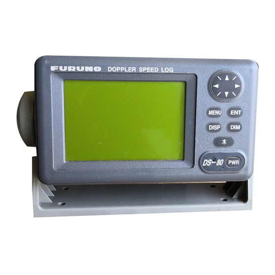
- Page 1 DOPPLER SPEED LOG Marine Speed and Distance Measuring Equipment (SDME) DS-80...
- Page 2 All rights reserved. All rights reserved. Printed in Japan Printed in Japan PUB.No. PUB.No. OME-72470 OME-72470 ( ( DAMI DAMI ) ) DS-80 DS-80 Your Local Agent/Dealer Your Local Agent/Dealer FIRST EDITION : FIRST EDITION : FEB. FEB. 2000 2000 : : FEB.
- Page 3 Continued use of the equipment can cause fire or electrical shock. Contact a FURUNO agent for service. Do not place liquid-filled containers on the top of the equipment.
- Page 4 A warning label is attached to the Distributor, Transceiver and Terminal Box. Do not remove the labels. If a label is missing or is illegible, contact a FURUNO dealer or agent about replacement. Name: Warning Label (1) WARNING Type: 86-003-1011-0 To avoid electrical shock, do not Code No.: 100-236-230...
-
Page 5: Table Of Contents
SPECIFICATIONS ... SP-1 FOREWORD... 1 SYSTEM CONFIGURATION ... 2 PRINCIPLE OF OPERATION... 3 REMARKS ON USAGE... 4 1 OPERATION OF DISPLAY UNIT . 5 1.1 Controls... 5 1.2 Turning the Power On/Off... 5 1.3 Adjusting Contrast, Panel Dimmer... 6 1.4 Selecting a Display... 6 1.5 Main Menu Operation... - Page 6 This page is intentionally left blank.
-
Page 7: Specifications
Output: Input: (2) Analog Signal (3) Distance run output (4) System Check signal DS-80 Fore-Aft: -10.0 to +40 knots through-the-water 0.00 to 999,999.99 nautical miles through-the-water Water depth greater than 3 m beneath the keel. 1.0 MHz 1.0% or 0.1 knots whichever is the greater 1.0% or 0.1 nm whichever is the greater... - Page 8 4. POWER SUPPLY (1) System Source 5. ENVIRONMENTAL CONDITION (IEC 60945) (1) Ambient Temperature (2) Relative Humidity (3) Vibration (4) Category of Equipment Display Unit/Distance indicator/Transceiver Unit: Transducer: Distributor/Terminal box: For protected area 6. COATING COLOR (1) Display Unit (2) Distribution Box (3) Transceiver Unit (4) Terminal Box (5) Analog Display...
-
Page 9: Foreword
The output is interfaced with ARPA, AIS, and other shipborne equipment in IEC 61162-1 format. The main features of the DS-80 are Simple operation. In most cases all that is required to display ship’s speed is to turn on the equipment. -
Page 10: System Configuration
TERMINAL BOX DS-802 DISTRIBUTION BOX DS-801 JUNCTION BOX CI-630 RANGE SWITCH BOX TRANSCEIVER UNIT DS-810 TRANSDUCER DS-820 SYSTEM CONFIGURATION DISPLAY UNIT DS-800 DIMMER MF-22L-1/MF-22L-2 DIMMER MF22L-1/MF22-2 TERMINAL BOX DS-802 DIMMER MF-22L-1/MF-22-2 ANALOG DISPLAY UNIT MF-22A-1 DS-389 SHIP'S MAINS 115/230 VAC IEC 61162-1 Input Power ON SW Signal Distance Run Signal... -
Page 11: Principle Of Operation
You can hear the change in pitch as the train passes. The DS-80 has a pair-beam, one directed in the fore direction and the other in the aft direction, which emits ultrasonic waves at an angle of to the waterline towards ship’s... -
Page 12: Remarks On Usage
Conditions Affecting the Accuracy (with ref to IMO A.824/3.3) The Doppler speed log DS-80 is designed for reliable and accurate performance through FURUNO’s long experience and advanced technology. It operates on the best choice of system frequency and power output. -
Page 13: Operation Of Display Unit
1.2.2 Power off Press the [POWER] switch to turn the power off. Note: Keep the DS-80 energized continuously unless it fails. Turning off the DS-80 may cause an inconvenience in associated equipment, such as a radar. Speed Distance Omnipad Selects items, options on menus. -
Page 14: Adjusting Contrast, Panel Dimmer
Adjusting Contrast, Panel Dimmer 1.3.1 Contrast 1. Press the [*] key to open the contrast adjustment dialog box. CONTRAST (0~63) EXIT: [ENT] 2. Press the Omnipad at the contrast. The setting range is 0 to 63 and the default setting is 48. 3. -
Page 15: Main Menu Operation
Main Menu Operation Functions of the DS-80 are selected through the menu. 1. Press the [MENU] key to open the menu. MENU DISTANCE RUN DISPLAY DEMO SYSTEM MENU SYSTEM MENU2 2. Press the Omnipad at a menu item (current selection is highlighted) and press the [ENT] key. - Page 16 MENU DISTANCE RUN DISPLAY DEMO SYSTEM MENU SYSTEM MENU2 2. Press the Omnipad at DISTANCE RUN DISPLAY and press the [ENT] key. DISTANCE RUN DISPLAY DATA DISPLAY CONTACT CLOSURE RESET 0.00nm ENT SET 3. Select DATA DISPLAY and press the [ENT] key.
-
Page 17: System Setting
5. Press the [MENU] key twice to close the menu. 1.7.4 Tracking depth Doppler shift measuring depth in the DS-80 is 2 m at default. If the speed readout is unstable due to air bubbles near the ship’s hull, increase or decrease the track depth to stabilize the readout. - Page 18 This is done at installation; no user adjustment is necessary. 1.7.6 Speed data selection 30 SEC When the DS-80 fails to work as an SDME, +0.0% 2.0 m the display unit can be used as a monitor +00˚...
-
Page 19: Demonstration Mode
1.7.7 System menu 2 The System Menu 2 contains the diagnostic test and selection of dimmer control and display language. 1. Press the [MENU] key to open the menu. 2. Select SYSTEM MENU 2 and press the [ENT] key. SYSTEM MENU2 TEST DIMMER INTERNAL... -
Page 20: Operation Of Optional Equipment
2 OPERATION OF OPTIONAL The Digital Indicator DS-830 and Distance Indicator DS-840 have the same controls as the display unit. This chapter explains the features which are not shared with the display unit. Digital Indicator DS-830, Distance Indicator DS-840 2.1.1 Selecting a display Press the [DISP] key to select the display mode. - Page 21 ANALOG DISPLAY UNIT CORRECTION DIAGRAM AT EXTREME TEMPERATURES Doppler Speed Log DS-80 CORRECTION FACTOR FOR ANALOG DISPLAY MF-22A-1 Example: If the analog speedometer reads 14.2 kt at a temperature of –15 C, the correct speed through the water is 15 kt. Failure of correction in low temperature can result in a maximum error of –0.8 kt or 5.3% for 14.2 kt readout.
-
Page 22: Maintenance, Troubleshooting
3 MAINTENANCE, TROUBLESHOOTING WARNING ELECTRICAL SHOCK HAZARD Do not open the equipment. Only qualified personnel should work inside the equipment. 3.1 Maintenance 3.1.1 Preventive maintenance Check the following points regularly to maintain performance. Check that the connectors on all units of the system are firmly fastened and free of rust. -
Page 23: Troubleshooting
Troubleshooting This section provides troubleshooting procedures. Advanced level troubleshooting should be done by referring to the Service Manual (optional supply). Problem General Loosened power cable Cannot turn on the power. Blown fuse Power is on but Contrast too low. nothing appears on the screen. -
Page 24: Diagnostics, Checking Program Number
Diagnostics, Checking Program Number The diagnostic facility checks the ROM, RAM, SIO and displays program ID. 1. Press the [MENU] key to open the menu. 2. Select SYSTEM MENU2 and press the [ENT] key. SYSTEM MENU2 TEST DIMMER INTERNAL /LANG. ENGLISH 3. -
Page 25: Digital Interface (Iec 61162-1 Edition 2)
4 DIGITAL INTERFACE (IEC 61162-1 Edition 2) I/O Sentences Input sentences of IEC61162_RX port GGA, VTG Output sentences of IEC61162_TX1, IEC61162_TX2 ports VBW, VLW (Talker: VD) Transmission interval 3 s for VBW; 1 s for VLW Data transmission Data is transmitted in serial asynchronous form in accordance with the standard referenced in 2.1 of IEC 61162-1. - Page 26 Schematic diagrams IEC61162 RX port DS-801 65P6010 F2047A-20P-B IEC61162_RX_A <11< IEC61162_RX_B <12< Load requirements as listener Isolation: Optocoupler Input Impedance: 44 ohms Max. Voltage: ±2.6V Threshold: 4 mA IEC61162 TX1 port Output drive capability Max. 20 mA ERJ_6GEY0R00V R121 22 R122 120 R123 120 R124 22...
- Page 27 IEC61162 TX2 port DS-801 65P6010 F2047A-20P-B <7< IEC61162_TX2_A IEC61162_TX2_B <8< Output drive capability Max. 20 mA R136 SN75ALS191PS R135...
-
Page 28: Sentence Description
Sentence Description GGA - Global positioning system (GPS) fix data Time, position and fix related data for a GPS receiver. Note: Item Only GPS quality indicator and antenna altitude above/below are used. - Page 29 VTG - Course over ground and ground speed The actual course and speed relative to the ground. $--VTG,x.x,T,x.x,M,x.x,N,x.x,K,a*hh<CR><LF> | | +--+----------------- 3 | | +--+----------------------- 2 +--+----------------------------- 1 1. Course over ground, degrees true 2. Course over ground, degrees magnetic 3.
- Page 30 VBW - Dual ground/water speed Water-referenced and ground-referenced speed data. $--VBW,x.x,x.x,A,x.x,x.x,A,x.x,A,x.x,A*hh<CR><LF> | | +-------- 9 | +----------- 8 | | +-------------- 7 | +----------------- 6 +-------------------- 5 | | +------------------------ 4 | +--------------------------- 3 | +------------------------------ 2 +---------------------------------- 1 1. Longitudial water speed, knots 2.
-
Page 31: Parts Location And Parts List
5 PARTS LOCATION AND PARTS LIST Parts Location Display unit DS-800 Distribution box DS-801 U10 (ROM) ICP Board 65P6000, parts side From right TB1, TB2, TB3 TB101 Distribution Box DS-801, inside view POWER switch JPW Board... - Page 32 Transceiver unit DS-810 TB101 POWER Switch KCP Board Transceiver Unit DS-810, inside view...
-
Page 33: Parts List
This equipment contains complex modules in which fault diagnosis and repair down to component level are not practicable (IMO A.694(17)/8.3.1). Only some discrete components are used. FURUNO ELECTRIC CO., LTD. believes identifying these components is of no use for shipborne maintenance; therefore, they are not listed in this manual. Major modules... - Page 34 ELECTRICAL PARTS LIST SYMBOL TYPE PRINTED CIRCUIT BOARD CABLE w/CONNECTOR CODE No. REMARKS SHIPPABLE ASSEMBLY...
- Page 35 ELECTRICAL PARTS LIST SYMBOL TYPE PRINTED CIRCUIT BOARD POWER SUPPLY ASSEMBLY SWITCH VARISTOR TRANSFORMER TERMINAL BOARD NOISE FILTER CABLE w/CONNECTOR CODE No. REMARKS SHIPPABLE ASSEMBLY...
- Page 36 ELECTRICAL PARTS LIST SYMBOL TYPE PRINTED CIRCUIT BOARD ASSEMBLY POWER SUPPLY ASSEMBLY SWITCH VARISTOR TERMINAL BOARD FUSE HOLDER POWER SUPPLY NOISE FILTER CODE No. REMARKS SHIPPABLE ASSEMBLY...
-
Page 37: Calibration Sheet
CALIBRATION SHEET... -
Page 38: Menu Overview
Default settings in bold italic. [MENU] key DISTANCE RUN DISPLAY DEMO SYSTEM MENU SYSTEM MENU2 MENU OVERVIEW DATA DISPLAY ( CONTACT CLOSURE , IEC 61162-1(VLW)) RESET (ON, OFF ) SET (0.0 nm-999999.99 nm, 0.00 nm ) SPEED (-10.0 to +40.0 kt, +10.0 kt ) DATA DISPLAY ( OFF , ON) SHIP SPD AVG (15, 30 , 45, 60 SEC) SPEED OFFSET (-25.0% to +25.0%, 0% ) -
Page 39: Index
Contrast ... 6 Control description ... 5 Demonstration mode... 9 Diagnostics... 14 Digital indicator... 12 Digital interface... 16 Digitial display ... 12 DIM key ... 6 Dimmer... 6 Distance run adjusting ... 9 display method... 8 resetting to zero ... 8 Fuse replacement...