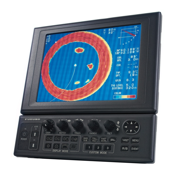
Furuno SEARCHLIGHT CH-250 Installation Manual
Searchlight sonar
Hide thumbs
Also See for SEARCHLIGHT CH-250:
- Operator's manual (118 pages) ,
- Installation manual (103 pages) ,
- Specification sheet (4 pages)
Table of Contents
Advertisement
Quick Links
SAFETY INSTRUCTIONS....................... i
SYSTEM CONFIGURATION ................. iii
EQUIPMENT LISTS .............................. iv
1. Mounting ........................................... 1
1.1 Monitor Unit/Control Unit .........................1
1.2 Transceiver Unit .......................................6
1.3 Hull Unit ...................................................9
1.4 Interface Unit..........................................21
1.5 Motion Sensor MS-100 (option) .............22
2. Wiring .............................................. 23
2.1 Wiring among Units................................23
2.2 Transceiver Unit .....................................26
2.3 Hull Unit .................................................29
2.4 Interface Unit..........................................30
SEARCHLIGHT SONAR CH-250
www.furuno.co.jp
Installation Manual
3. ADJUSTMENTS ............................... 31
3.1 General Checks..................................... 31
3.2 TX Frequency Checking........................ 32
3.3 Heading Adjustment/Soundome Setting
......................................................... 34
3.4 Adjustment of Motion Sensor ................ 37
3.5 System Back Up.................................... 38
3.6 Setting of Interface Unit......................... 40
Input/Output Description.................... 41
PACKING LISTS ................................ A-1
OUTLINE DRAWINGS ....................... D-1
INTERCONNECTION DIAGRAMS..... S-1
Advertisement
Table of Contents

Related Manuals for Furuno SEARCHLIGHT CH-250


Summary of Contents for Furuno SEARCHLIGHT CH-250
-
Page 1: Table Of Contents
3.2 TX Frequency Checking... 32 3.3 Heading Adjustment/Soundome Setting ... 34 3.4 Adjustment of Motion Sensor ... 37 3.5 System Back Up... 38 3.6 Setting of Interface Unit... 40 Input/Output Description... 41 PACKING LISTS ... A-1 OUTLINE DRAWINGS ... D-1 INTERCONNECTION DIAGRAMS... S-1 www.furuno.co.jp... - Page 2 : +81-(0)798-65-4200 Printed in Japan All rights reserved. Pub. No. IME-13160-K4 (YOSH ) CH-250 The paper used in this manual is elemental chlorine free. ・FURUNO Authorized Distributor/Dealer A : MAR K4 : SEP . 10, 2007 *00080895011* *00080895011* *00080895011* *00080895011*...
-
Page 3: Safety Instructions
Also confirm that the transducer will not loosen by ship's vibration. The installer of the equipment is solely responsible for the proper installation of the equipment. FURUNO will assume no responsibility for any damage associated with improper installation. WARNING Installe the specified transducer tank in accordance with the installation instructions. - Page 4 CAUTION Ground the equipment to prevent electrical shock and mutual interference. Observe the following compass safe distances to prevent deviation of a magnetic compass: Standard Steering 0.80 m Monitor unit/ Control unit Transceiver 0.50 m unit Interface 0.95 m unit Install the monitor unit MU-100C out of direct sunlight.
-
Page 5: System Configuration
INTERFACE UNIT IF-8000 Note 2 Navigator Display Unit VGA Ext. Monitor TRANSCEIVER UNIT CH-253 HULL UNIT SPEAKER DA T A/VIDEO OUT Speaker Motion Sensor Note 1: MU-100C is the standard supply display unit. An external monitor may be connected via the interface unit (option). -
Page 6: Equipment Lists
Standard Supply Name Type Control Unit/ CH-252/ Monitor Unit MU-100C Control Unit CH-252 Interface Unit IF-8000 Transceiver Unit CH-253 CH-254 Hull Unit CH-255 SP06-01100 Spare Parts SP06-01110 SP06-01101* Installation Materials FP02-05100 Accessories FP06-01120* 06-021-2121 EQUIPMENT LISTS Code no. Remarks Not supplied with blackbox type Not supplied with unibody type For blackbox type 400 stroke... - Page 7 Hull Unit (1) Code no. Type 000-068-515 CH-254-1-60-22-35 000-068-516 CH-254-1-88-22-35 000-068-517 CH-254-1-150-22-35 000-068-518 CH-254-1-180-22-35 000-068-519 CH-254-1-240-22-35 000-068-559 CH-254-1-60-22-52 000-068-560 CH-254-1-88-22-52 000-068-561 CH-254-1-150-22-52 000-068-562 CH-254S-1-180-22-52 000-068-563 CH-254S-1-240-22-52 000-068-520 CH-254-1-60-38-52 000-068-521 CH-254-1-88-38-52 000-068-522 CH-254-1-150-38-52 000-068-523 CH-254S-1-180-38-52 000-068-524 CH-254S-1-240-38-52 000-068-525 CH-254-2-60-22-35 000-068-526 CH-254-2-88-22-35 000-068-527 CH-254-2-150-22-35 000-068-528...
- Page 8 Drive Unit CH-2551 Soundome CH-2542 Flange CH-2543 Assembly Kit for CH-2544 field Shaft SHJ-0006-1 06-007-1572-0 Sonar Oil 4 lit. Code no. Remarks 1 set 1 set See the following Soudome table. 006-557-810 1 set Flange, grease cotton 006-557-820 1 set...
- Page 9 Shaft parts Name Type Pipe cap SHN-0011-0 Jubilee Clip 1X28-41 Hex. bolt M10X35 SUS304 000-862-175 U-nut M10 SUS304 Flat washer M10 SUS304 Tank parts Name Type Hex. bolt M20X80 SUS304 000-801-893 Hex. nut M20 SUS304 Flat washer M20 SUS304 Spring washer M20 SUS304 Adhesives Name...
- Page 10 Cables for Installation materials Type Code no. CP06-01200 000-068-496 CP06-01201 000-068-497 CP06-01202 000-068-498 CP06-01203 000-068-499 CP06-01204 000-068-500 CP06-01205 000-068-502 Control unit cable Type Code no. CP02-06600* 000-012-486 CP02-06610* 000-012-480 CP02-06620* 000-012-481 Options Name Type Remote Controller CH-256-E Interface Unit IF-8000 Motion Sensor MS-100 Speaker...
-
Page 11: Mounting
1.1 Monitor Unit/Control Unit This searchlight sonar has two types of shipment, standard type which is shipped with monitor unit and blackbox type which is shipped without monitor unit, but has interface unit. For blackbox type, see page 4. - Page 12 2. For unibody mounting; a) Fasten the bracket at the rear of monitor and control units with four binding screws (M4x10). 3. For separate/blackbox mounting; Dismount the coupling plate to separate monitor unit and control unit. Attach the bracket at rear of the monitor unit with four binding screws (M4x10). 4.
- Page 13 Flush mounting Flush mounting for unibody (Type: OP06-16, Code no.: 006-556-300) Name Fixing metal Self-tapping screw Hex. bolt 1. Make holes at the place to mount (W287 x H297). 2. Fasten monitor and control units with the fixing metal (supplied as option) and four hex. bolts (supplied as option).
- Page 14 Flush mounting for control unit Type: OP02-83-1.5, Code no.: 001-413-600 (1.5 m cable) OP03-83-5, Code no.: 001-413-610 (5m cable) Name Fixing metal 06-021-2101-2 Self-tapping screw 5x20 Hex. bolt M4x12 MJ-A10SPF0002-0 Cable assembly MJ-A10SPF0002-0 1. Make holes at the place to mount (W287 x H87). 2.
-
Page 15: Control Unit
1.1.4 Control unit On blackbox type, fix the control unit to the mounting plate (supplied as accessories). See the parts list of FP06-01120 and outline drawings at the back of this manual. 1. Fix the mounting plate to the place selected with two tapping screws (5x20, supplied). 2. -
Page 16: Transceiver Unit
Transceiver Unit 1.2.1 General mounting considerations The mounting location should be well ventilated and dry. The unit can be mounted on bulkhead or the deck. Secure the maintenance space shown in drawing below for ease of maintenance and service. The maximum cable length between the transceiver unit and the raise/lower drive unit cable is 50 m. - Page 17 An obstacle in the fore direction not only causes a shadow zone but also aerated water, resulting in poor sonar performance. Be sure to locate the transducer well away from any obstacle in the fore direction. Mounting method A typical mounting method is shown in the outline drawing at the back of this manual.
- Page 18 For small FRP ship For small FRP ship retraction tank should be 2 degrees against ship’s draft. Therefore, this creates high water pressure in the tank because of the resistance at the rear of the tank well. To solve this problem, attach a fin to the hull at the location shown in figure below. This fin makes a smooth stream in the retraction dome.
-
Page 19: Hull Unit
1.3.4 Assembling and mounting of hull unit The hull unit is shipped as the parts shown in the hull unit kit on Equipment Lists (page iv and after). Assemble the hull unit as shown in the procedure below. Necessary tools Name Wrench Wrench... - Page 20 Hex. bolt (M10X30) Spring washer Flat washer Shaft sleeve and raise/lower drive unit assembly 3. Pass the transducer cable through the main shaft. Raise/lower section Flat washer Trunnion pin Shaft sleeve...
- Page 21 4. Fully screw main shaft into the soundome neck, and then unscrew by four turns. Coat threads with adhesive (HIGH SUPER). Applying Adhesive (HIGH SUPER) to main shaft 5. Screw in main shaft completely. 6. As shown in the drawing below, confirm that the narrowest gap between the tank guide, and retraction tank in the range (20 to 170 mm) is within 0.5 mm.
- Page 22 7. If the gap at a side is more than 0.5 mm, install a shim to make the gap within 0.5 mm. a) Unscrew four M10x50 bolts. b) Unscrew four countersunk screws, then attach the shim with the countersunk screws as shown below.
- Page 23 The table below shows tank length and necessary shim thickness. In addition, the shim thickness shown is for one side. For example, when cutting the 1800 mm tank to 800 mm, the tank inside diameter is 191.25 mm, shim thickness is 2.5 mm as shown the table in below. 1800 1600 1400...
- Page 24 8. Apply THREE BOND 1104 to the inside of tank guide. And then, fasten tank guide at the neck* of the main shaft securely with M10X80 bolts. Hex. Bolt (M10X80) Bow Mark 9. Pass the main shaft through shaft sleeve. 10.
- Page 25 11. Face the bow mark on the soundome with the bow mark on the shaft sleeve, and then fix the main shaft with and shaft retainer. 12. Fix the jubilee clip to the main shaft. Note: Attach the shaft retainer so it is 15 mm from the top of the shaft. The soundome is then placed 10 mm above the bottom of tank when retracted.
- Page 26 (supplied) so the level is 5 cm on the top of the soudome. Keep the soundome packing for future use. Ball wrench Socket head cap screw 10pcs, M5x30 Spring washer Soundome Detaching the soundome Sonar oil 5 cm Stand the soundome upright on top the soundome packing. Filling the soundome with sonar oil O-ring Remove. Protection sponge...
- Page 27 Keep oil away from eyes. Where protective goggles when working with the oil. The oil cause inflammation of the eyes. Do not touch the oil. The oil can cause inflammation of the skin. Wear protective gloves when working with the oil. Do not ingest the oil.
- Page 28 When the soundome is painted to keep marine life off the transducer, observe the following precautions: Use only anti-fouling paint type MARINE STAR 20 (Manufacture: Chugoku Marine Paint Co., Ltd., Japan). Paint only the plastic portion of the dome. Painting the metal parts causes corrosion. 19.
- Page 29 22. Fix the shaft sleeve and retraction tank with hex bolts, flat washers and spring washers. Hex bolt Shaft retainer 15 mm 1-2 mm Jubilee clip Main shaft 10 mm...
- Page 30 Checking manual raise/lower of soundome with hand crank Perform this check after all wiring has been completed. Turn the main power off before this check, otherwise the raise/lower motor action may cause injurely. 1. Turn off the breaker on the hull unit. 2.
-
Page 31: Interface Unit
Interface Unit For the blackbox type, the interface unit is shipped as standard. 1.4.1 General mounting considerations The mounting location should be well ventilated and dry, avoiding splay or rain. The unit can be mounted on a bulkhead or the deck. Secure the maintenance space shown in drawing below for ease of maintenance and service. -
Page 32: Motion Sensor Ms-100 (Option)
Motion Sensor MS-100 (option) The MS-100 measures ship’s pitching and rolling angles with sensor using the principles of the gyroscope. The MS-100 is free from error caused by ship’s vertical and horizontal motion. Therefore, it can be installed at any convenient location. However, ship’s semi-permanent inclination due to loading imbalance cannot be detected. -
Page 33: Wiring
The raise/lower drive motor and breaker are different depending on ship’s mains. Install the main switch for the sonar where it can be easily accessed. Turn off this switch when the sonar is not being used, to reduce power consumption and to prevent the transducer from slipping by vibration. - Page 34 06S4078 06S4078 (5/10m) (5/10m) HULL UNT SPEAKER Speaker (w/cable) Ext. KP 06S4080( Note1: Cable between the monitor unit and control unit 06S4079 (0.15m standard, for uni body type) 06S4085 (1.5m option, for separate type) 64S4063 (5m option, for separate type) Note2: A VGA monitor (local supply) can be added by the connecting the optional interface unit.
- Page 35 Interface unit 06S4078 (5/10m) 06S4078 (5/10m) HULL UNT SPEAKER Speaker (w/cable) Ext. KP Note1: Two interface units are connectable. Note2: For blackbox type, the display monitor (local supply) is reqired. < = Note3: *a+b 15m Note 1 64S4063(5m) Control unit, back view 12-32VDC DATA/VIDEO OUT MOTION SENSOR...
-
Page 36: Transceiver Unit
Transceiver Unit Connect the cables as figure in below. Remove the cover of the power terminal board. *Note SPEAKER External speaker SC-05WR 06S4080 Hull unit External KP CH-254/CH-255 *Note: Fix the braided shield with the clamp. 06P0240 NH6P DATA/VIDEO OUT MOTION SENSOR Monitor unit Motion... - Page 37 2.2.1 Synchronizing Transmission with Echo Sounder or Other Sonar To synchronize transmission of the CH-250 with an echo sounder or other type of sonar, connect it as shown below. Transceiver unit 06P0240 EXT_SW Connection of transceiver unit to other sonar Menu setting 1.
- Page 38 5. Press the ["] to select EXTERNAL. 6. Press the [MENU] key to close the user menu. Note: Outputting KP of CH-250 to other sonar, echo sounder Transceiver unit 06P0240 positive Outputting KP of CH-250 to other sonar, echo sounder TX RATE EXT.
-
Page 39: Hull Unit
Hull Unit Pass the cables to 06P0426 Board through the cable protectors. 06P0246 06P0243 *Note: Fix the braided shield with cable clamp. *Note *Note *Note Fasten glands securely by hands. Cable from transducer 06S4081 Cable from transceiver unit 06S4080 Power cable 250V-DPYCYS-2.5 Power Switch Should always be in up (ON). -
Page 40: Interface Unit
TLL level H, V, Negative polarity Note: Cut and remove the rubber covers as below to attach connectors to the interface unit.. Note: Connect control unit or navigator equipment to either interface unit or monitor unit (supplied by FURUNO). CONT NMEA... -
Page 41: Adjustments
3. ADJUSTMENTS General Checks Check Item Retraction tank level Clearance between transducer and bottom of retraction tank when transducer is completely retracted by hand crank Transducer travel (lowered by hand clank) Note: When checking, a clearance of approximately 1 meter is required under the bottom of the transducer. -
Page 42: Tx Frequency Checking
Check Item Wiring check Rejecting source of noise and interference Earth Ship’s mains voltage Watertightness TX Frequency Checking Check the TX frequency after the installation. 1. Press the [MENU] key to open the user menu. 2. Press the cursor pad to select SYS at the top of the menu display. MENU COM1 COM2 HORZ VERT GO TO SYS MENU... - Page 43 7. Check the frequency at the TX FREQUENCY line on the test display. 8. Press the [MENU] key several times to close the menu. ** SYSTEM MENU ** SYSTEM SETTING: RANGE-SONAR MODE RANGE-VERTICAL MODE RANGE-E/S MODE RANGE-TRACK MODE COLOR PALETTE...
-
Page 44: Heading Alignment
Heading Alignment/Soundome Setting Heading alignment The heading line can be compensated through the system menu ( –30 to +30 ). 1. Locate a target (buoy, etc.) in the bow direction and display it on the screen at close range, read deviation. The heading alignment is correct when the target is displayed at 12 o’clock on the screen. - Page 45 Open the SYSTEM MENU following step 1 to 4 in the above. Select SYSTEM SETTING, and then press the [ ] to open the SYSTEM SETTING 1 menu. ** SYSTEM MENU ** SYSTEM SETTING: RANGE-SONAR MODE RANGE-VERTICAL MODE RANGE-E/S MODE RANGE-TRACK MODE COLOR PALETTE...
- Page 46 MENU POSITION TRACK CURRENT DATA HEADING INDICATION : TRUE NORTH MARK CSE DATA NAV DATA TVG CORRECTION UNIT TEMP TARGET L/L CUSTOM KEY EMPHASIS MODE ETA MARK : SELECT Press the cursor pad to select 2 and press the [ ] to show SYSTEM SETTING 2 menu. MENU STABILIZER AUTO RETRACTION...
-
Page 47: Adjustment Of Motion Sensor
COM1 COM2 HORZ VERT SHORT-CUT MENU: END : CHANGE Display to select the system menu ** SYSTEM MENU ** SYSTEM SETTING: RANGE-SONAR MODE RANGE-VERTICAL MODE RANGE-E/S MODE RANGE-TRACK MODE COLOR PALETTE LANGUAGE SYSTEM BACKUP LOAD BACKUP DATA HEADING OFFSET, DRAFT OFFSET... -
Page 48: System Back Up
6. Press [ ] [ ] to select ROLL ANGLE or PITCH ANGLE. 7. Press [ ] [ ] to adjust (-10 to +10 ). By using a clinometer or other means, measure ship’s semi-permanent inclination angle. Take the polarity of the angle as follows. For example, if the stern is 3 down, set -3 . ROLL ANGLE PITCH ANGLE Stern up 8. - Page 49 The backup data is loaded, and then return to the system menu. 9. Press the [MENU] key to return to the normal display. ** SYSTEM MENU ** SYSTEM SETTING: RANGE-SONAR MODE RANGE-VERTICAL MODE RANGE-E/S MODE RANGE-TRACK MODE COLOR PALETTE LANGUAGE...
-
Page 50: Setting Of Interface Unit
Setting of Interface Unit Set DIP switch S1 in the interface unit as follows. The monitor unit MU-100C or the interface unit is connected to DATA/VIDEO OUT port of the interface unit : all OFF. Nothing is connected to DATA/VIDEO OUT port of the interface unit : all ON. Processor Unit Processor... -
Page 51: Input/Output Description
Input/Output Description The CH-250 can receive/transmit the following sentences in NMEA 0183 format. Input GLL: GPS position VTG: Ground speed/true course DBT: Depth (Ignore talker, NMEA Ver1.5) DBS: Depth (Ignore talker) DPT: Depth (Ignore talker, NMEA Ver2.0) GGA: GPS position/Speed/Course (Ignore talker) VDR: Current direction/current speed (Ignore talker) RMA:... - Page 52 This page is intentionally left blank.
- Page 59 D-2A...
- Page 66 Takahashi T Takahashi T...
- Page 71 D-13 Y. Hatai...
-
Page 78: Interconnection Diagrams
CH-250/S E.MIYOSHI 名 称 カラーLCDサーチライトソナー TAKAHASHI.T Y. Hatai 相互結線図 MASS NAME COLOR SEARCHLIGHT SONAR REF. No. INTERCONNECTION DIAGRAM C1316-C01- D FURUNO ELECTRIC CO., LTD. 操作部 CONTROL UNIT CH-252 2B1 PNL 06P0239 TRXTD-A TRXTD-B CONTD-A CONTD-B PSW-H PSW-C +12V SCAN-REV F.GND リモートコントローラ... - Page 79 E.MIYOSHI 名 称 カラーLCDサーチライトソナー(I/Fユニット使用) TAKAHASHI.T Y. Hatai 相互結線図 MASS NAME COLOR SEARCHLIGHT SONAR (W/ I/F UNIT) REF. No. INTERCONNECTION DIAGRAM C1316-C02- D FURUNO ELECTRIC CO., LTD. 操作部 CONTROL UNIT CH-252 DISP 2B1 PNL 06P0239 MJ-A10 SPFD TRXTD-A TRXTD-B CONTD-A CONTD-B...