Nortel BayStack Instant Internet 100-S User Manual
Nortel baystack 100-s: user guide
Hide thumbs
Also See for BayStack Instant Internet 100-S:
- Using manual (344 pages) ,
- Install manual (104 pages) ,
- Reference (98 pages)

Related Manuals for Nortel BayStack Instant Internet 100-S


Summary of Contents for Nortel BayStack Instant Internet 100-S
- Page 1 Setting Up the BayStack Instant Internet 100-S Unit Part No. 209374-A November 2000 4401 Great America Parkway Santa Clara, CA 95054...
-
Page 2: Statement Of Conditions
Nortel Networks NA Inc. does not assume any liability that may occur due to the use or application of the product(s) or circuit layout(s) described herein. - Page 3 EC Declaration of conformity This product conforms to the provisions of the R&TTE Directive 1999/5/EC. Japan/Nippon requirements only Voluntary Control Council for Interference (VCCI) Statement Taiwan requirements Bureau of Standards, Metrology and Inspection (BSMI) Statement Canada requirements only Canadian Department of Communications Radio Interference Regulations This digital apparatus (BayStack Instant Internet 100-S) does not exceed the Class A limits for radio-noise emissions from digital apparatus as set out in the Radio Interference Regulations of the Canadian Department of Communications.
- Page 4 Repairs to certified equipment should be coordinated by a representative designated by the supplier. Any repairs or alterations made by the user to this equipment, or equipment malfunctions, may give the telecommunications company cause to request the user to disconnect the equipment. Users should ensure for their own protection that the electrical ground connections of the power utility, telephone lines and internal metallic water pipe system, if present, are connected together.
- Page 5 FCC. 4. If you experience trouble with the unit, please contact the Nortel Networks Technical Solutions Center in your area for service or repairs. Repairs should be performed only by service personnel authorized by Nortel Networks.
- Page 6 Connecting an Instant Internet unit to the network Important safety information To avoid contact with electrical current: • Never install electrical wiring during an electrical storm • Never install telephone jacks in wet locations unless that jack is specifically designed for wet locations •...
- Page 7 Connecting an Instant Internet unit containing an ISDN modem without NT1 This version of the product is equipped with two standard 8-pin RJ-45 jacks for connection to the NT1 (the BRI line can be attached to either jack, and the unused jack can be used to connect a second ISDN device). Instant Internet ISDN Device 9611EA...
- Page 8 90 days from the date Software is first shipped to Licensee. Nortel Networks will replace defective media at no charge if it is returned to Nortel Networks during the warranty period along with proof of the date of shipment.
- Page 9 Licensee fails to comply with any of the terms and conditions of the license. Upon termination for any reason, Licensee will immediately destroy or return to Nortel Networks the Software, user manuals, and all copies. Nortel Networks is not liable to Licensee for damages in any form solely by reason of the termination of this license.
- Page 10 209374-A...
-
Page 11: Table Of Contents
Setting the voltage selector switch ........ - Page 12 Switch settings for special configurations ........52...
- Page 13 Appendix A Technical specifications ........71 Physical specifications .
- Page 14 Contents 209374-A...
- Page 15 Figures Figure 1 Front panel of the Instant Internet 100-S unit ..... . 34 Figure 2 Rear panel of the Instant Internet 100-S unit ..... . 35 Figure 3 Removing screws from cover of Instant Internet 100-S unit .
- Page 16 Figures 209374-A...
- Page 17 Table 5 Voltage selector switch settings ....... . 40 Table 6 Switch settings for normal operation .
- Page 18 Tables 209374-A...
-
Page 19: Preface
Before using this manual, you need to do two things. First, write down the model number and serial number of your Instant Internet unit. You will need this information if you have to call Nortel Networks Technical Support. Model and serial numbers are located on the back panel of your Instant Internet unit. -
Page 20: Acronyms
Preface Acronyms The following acronyms are used in this manual: CENELEC CHAP ISDN Kb/s Mb/s MDI-X 209374-A Alternating Current Attachment Unit Interface Certification Body Certification of Electrical Equipment European Committee for Electrotechnical Standardization Challenge Handshake Authentication Protocol Canadian Standards Associates Underwriter Laboratories testing to Canadian standards Decibels Audible Dual Inline Pins... -
Page 21: Related Publications
NEMA POTS PPPoE SMTP SPID Related publications For more information about using Instant Internet, refer to the following publications: • Important Information for the BayStack Instant Internet Version 7.11 (Part number 307603-E) Provides instructions for viewing documentation and installing the Instant Internet software and third-party applications (Adobe Acrobat Reader, Netscape Communicator, and AniTa Terminal Emulator). - Page 22 Go to Adobe Systems Web at download a free copy of Acrobat Reader. You can purchase selected documentation sets, CDs, and technical publications though the Internet at the 209374-A www25.nortelnetworks.com/library/tpubs/ www1.fatbrain.com/documentation/nortel URL. Find the www.adobe.com URL to URL.
-
Page 23: How To Get Help
How to get help If you purchased a service contract for your Nortel Networks product from a distributor or authorized reseller, contact the technical support staff for that distributor or reseller for assistance. If you purchased a Nortel Networks service program, contact one of the following... - Page 24 Preface 209374-A...
-
Page 25: Chapter 1 Introduction
Instant Internet unit, and any requirements and compatibility issues. Caution: Before you install your unit, make sure that the power voltage selector switch setting matches your power voltage. For details, refer to “Setting the voltage selector switch” on page Instant Internet package The Instant Internet package contains: •... -
Page 26: Available Options
For contents, see Available options The Instant Internet 100-S unit is shipped with a seven-port autosensing, autonegotiating 10/100 Ethernet switch on the front of the unit, a full-duplex/ half-duplex autonegotiating 10/100 megabits per second (Mb/s) Ethernet connection, and one of the following: •... -
Page 27: Installation Preparation
Chapter 2 Installation preparation This chapter describes steps you should follow in preparing for Internet access, explains some decisions you need to make before you install your Instant Internet 100-S unit, and provides an installation checklist and worksheet. Preparing for Internet access To prepare for access to the Internet: Obtain installation and service from your local telephone company (telco). -
Page 28: Making Decisions
Send an e-mail message to support@nortelnetworks.com. Be sure to have your provider’s name, location, and contact-person’s phone number so that Nortel Networks can create a dial-up script specific to your ISP’s access requirements and add your ISP to the list. -
Page 29: Installation Checklist
Installation checklist Use the checklist in Table 1 item, record the information in the Table 1 Installation checklist ✔ Item Type of Account Dial-up Protocols ISDN Service Connect-Time Charges PPPoE Chapter 2 Installation preparation to ensure a smooth installation. As you check off each “Installation worksheet”... - Page 30 America, you can choose ! Default as your provider when you configure the unit and then enter your name servers. If your ISP is not on the Nortel Networks list, call the Nortel Networks Technical Solutions Center at 800-2LANWAN, Express Routing Code 169#, and provide some additional information so that Nortel Networks can create a dial-up script specific to your ISP’s...
-
Page 31: Installation Worksheet
Chapter 2 Installation preparation Installation worksheet ISP User Name: _________________________________________________ This is the user name you enter to log on to your ISP account. ISP Password: ___________________________________________________ This is the password you enter to log on to your ISP account. ISP Connection Phone Number: ____________________________________ This number is the primary phone number you dial to access your ISP account. - Page 32 Chapter 2 Installation preparation 209374-A...
-
Page 33: Instant Internet 100-S Hardware Installation
• A seven-port autosensing, autonegotiating Ethernet switch provides a means for connecting to your network and enables you to eliminate an extra switch or hub on your LAN. Each port adapts to the correct network speed (10 Mb/s or 100 Mb/s), the duplex mode of the connected device, and the correct MDI status of the cable. -
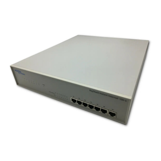
Page 34: Figure 1 Front Panel Of The Instant Internet 100-S Unit
Seven 10/100 Link/Activity LEDs (labeled S1–S7) display port status for the switch. For details, refer to functions,” on page • Seven FDX LEDs (labeled S1–S7) display port mode status for the switch. For details, refer to page Figure 1 illustrates the front panel of the unit. -
Page 35: Figure 2 Rear Panel Of The Instant Internet 100-S Unit
Power switch 115 / 230 V ~ 50 / 60 Hz , 4A / 2A Power supply connector Setting Up the BayStack Instant Internet 100-S Unit Power voltage selector switch 230VAC 115VAC 9859EB... -
Page 36: Interfaces
Chapter 3 Instant Internet 100-S hardware installation Interfaces Each unit has an autosensing, autonegotiating seven-port 10/100 Ethernet switch, a full-duplex/half-duplex autonegotiating Ethernet LAN interface, and one of several communications interface cards. Note: The interface card(s) in your Instant Internet unit may not look exactly like those depicted in the illustrations. -
Page 37: Table 3 Communications Interface Cards
Table 3 describes the communications interface cards available for your Instant Internet 100-S unit. Table 3 Communications interface cards Interface name Interface card Analog Dual Analog ISDN U ISDN S/T 1-Meg Modem Chapter 3 Instant Internet 100-S hardware installation Phone Line 9858EA 9857EA... -
Page 38: Power Cords
Chapter 3 Instant Internet 100-S hardware installation Power cords The AC power receptacle accepts the AC power cord (supplied). For installation outside of North America, make sure that you have the proper power cord for your region. Any cord used must have a CEE-22 standard V female connector on one end and must meet the IEC 320-030 specifications. - Page 39 Chapter 3 Instant Internet 100-S hardware installation Caution: Please read immediately. Inspect this power cord and determine if it provides the proper plug and is appropriately certified for use with your electrical system. Immediately discard this cord if it is inappropriate for your country’s electrical system and obtain the proper cord as required by your national electrical codes or ordinances.
-
Page 40: Setting The Voltage Selector Switch
If the switch is set to 110 and the voltage that the unit is connecting to is 200 or above, you must return the unit for repair. If the switch is set to 230 and the voltage that the unit is connecting to is 127 or below, the unit may not function properly. -
Page 41: Instant Internet Quick Installation
Be sure to choose a location near your router and LAN or WAN hubs and close to an electrical outlet. Note: Before you begin the installation, make sure that the power voltage selector switch matches your power voltage (see voltage selector switch” on page to normal operation (see... - Page 42 (12.7cm) at the back for power cord clearance and ventilation. Continue with step 2. With the tip of a pen, slide the power voltage selector switch to the power voltage setting that matches your power voltage. For more information, see “Setting the voltage selector switch”...
-
Page 43: Mounting Your Instant Internet Unit On The Wall
(phone jack, ISDN jack, cable modem, 1-Meg modem, or external device). Do one of the following: • To use the Instant Internet unit as your LAN switch, attach up to seven workstations to the seven-port switch on the front panel of the unit. •... -
Page 44: Figure 3 Removing Screws From Cover Of Instant Internet 100-S Unit
Chapter 3 Instant Internet 100-S hardware installation Attenzione: Le viti e la struttura a muro devono essere in grado di sostenere il peso del dispositivo, oltre a quello dei cavi di rete e di alimentazione collegati. Precaución: Los tornillos y la composición de la pared deben ser capaces de sostener el peso del dispositivo más el peso adicional de los cables de red y cables de alimentación conectados. -
Page 45: Figure 4 Mounting The Instant Internet 100-S Unit To The Wall
Chapter 3 Instant Internet 100-S hardware installation Note: The mounting bracket is designed so that it will work on either side of the Instant Internet unit. Only three of the six holes in the mounting bracket are used on each side of the unit. Position your unit on the wall vertically as shown in The front panel of your unit should be facing the ceiling. - Page 46 Chapter 3 Instant Internet 100-S hardware installation 209374-A...
-
Page 47: Seven-Port Autosensing Switch Specifications
Instant Internet 10/100 Ethernet switch overview The seven-port switch on the front of the Instant Internet unit has seven 10/100 autosensing ports. Each port automatically senses and adapts to the operating environment, regardless of the type of cable (straight-through or crossover) plugged into the port, or whether the device at the other end of the cable is an Ethernet card, such as in a PC, or another hub or switch. -
Page 48: Switch Features
• Store-and-forward switching architecture. • One MB buffer memory. When you plug an Ethernet cable into a port, the switch: • Autosenses the transmission speed (10 Mb/s or 100 Mb/s) of the connected device. • Autonegotiates with the connected device to operate in full- or half-duplex mode. -
Page 49: Mdi/Mdi-X Autosensing Capability
Chapter 4 Seven-port autosensing switch specifications MDI/MDI-X autosensing capability When you plug an Ethernet cable into a port, the switch autosenses whether the cable is MDI-X (normal, or straight-through) or MDI (uplink, or crossover). This feature enables you to connect the Instant Internet unit to another Ethernet connection regardless of whether you are using a straight-through cable or a crossover cable. - Page 50 Chapter 4 Seven-port autosensing switch specifications 209374-A...
-
Page 51: Dip Switch Settings
Chapter 5 DIP switch settings This chapter describes the Dual Inline Pins (DIP) switch settings for your Instant Internet 100-S unit, including those for normal operation and for resetting your unit’s password and configuration settings. DIP switches DIP switches enable you to configure your Instant Internet unit for a particular type of operation. -
Page 52: Switch Settings For Normal Operation
• Erase the password • Erase the password and other user-defined system configuration • Disable the switch settings for resetting the password and user-defined configurations • Reset the original default factory settings Table 7 shows the switch settings for resetting your unit’s password. -
Page 53: Table 8 Switch Settings For Resetting The Password And User-Defined
Table 9 shows the switch settings to disable the switch settings for resetting the password and user-defined configurations Table 9 Switch settings to disable switch settings for resetting the password and user-defined configurations • •... -
Page 54: Resetting Your Instant Internet Unit
Table 10 Switch settings for resetting factory default conditions Caution: If you use these switch settings to reset your unit to the factory default conditions, the following user-defined settings are removed or reset: password, hosts, port mappings, unit configuration, access restrictions, unit registration, and encryption authorization. - Page 55 Note: If you used the switch settings in password and configuration switch settings, the Power LED glows amber and LEDs 1–8 flash red in the sequence of the selected switch settings. Turn off your unit. Reset the switches for normal operation.
- Page 56 Chapter 5 DIP switch settings 209374-A...
-
Page 57: Leds: Support And Diagnostic Functions
LEDs on the left indicate failures and operational status of the unit. The Power LED is always lit when your unit is turned on. The 14 LEDs at the bottom, center of the unit, display status and settings for the seven-port switch. Figure 6 illustrates the LEDs on the front of the Instant Internet 100-S unit. -
Page 58: Leds 1 Through 8 And Power Led At Power-Up Sequence
If a failure occurs during the power-up sequence, the Power LED glows amber, and one or more of LEDs 1 through 8 glow red. This sequence indicates a hardware problem. Call the Nortel Networks Technical Solutions Center (page 23) for assistance. -
Page 59: Leds 1 Through 8 And The Power Led During Operation
LEDs 1 through 8 and the Power LED during operation After the power-up sequence is complete, the LEDs indicate status and activity during operation as shown in Table 11 LED status and appearance during operation LED # Color Appearance Power Green Solid Power Green and Solid Green and... -
Page 60: Using The Seven-Port Autosensing Switch Leds For Troubleshooting
Using the seven-port autosensing switch LEDs for troubleshooting The seven-port autosensing switch has two LEDs for each port on the switch. The top row of these LEDs displays speed, link, and activity. The bottom row of LEDs displays whether the unit is operating in full- or half-duplex mode. -
Page 61: Out-Of-Band Management Support
Chapter 7 Out-of-band management support This chapter describes how to set up your Instant Internet unit for out-of-band management. This feature enables you to configure the Instant Internet unit without installing the unit on a network or loading the Instant Internet management software. -
Page 62: Configuring The Instant Internet Unit Through A Pc Direct Connection
Chapter 7 Out-of-band management support Configuring the Instant Internet unit through a PC direct connection To configure the unit with a PC using the out-of-band management feature, you must: • Connect the unit to the PC. • Use terminal emulation software to configure and establish a connection. Connecting a PC to the Instant Internet unit This procedure assumes that the Instant Internet unit is installed, turned on, and ready for operation. -
Page 63: Configuring A Direct Connection
Configuring a direct connection Regardless of the terminal emulation environment you use, you must set the connection speed to 115200, set the flow control to hardware (RTS/CTS), and connect the Instant Internet unit’s AUX port to the PC’s COM1 port. This procedure provides instructions for configuring the HyperTerminal terminal emulation software. -
Page 64: Figure 8 Hyperterminal Connect To Dialog Box
Chapter 7 Out-of-band management support Figure 8 HyperTerminal Connect To dialog box From the Connect using list, select COM1, and then click OK. The COM1 Properties dialog box opens Figure 9 HyperTerminal Com1 Properties dialog box 209374-A (Figure... -
Page 65: Configuring The Instant Internet Unit Through A Dial-Up Connection
When you successfully log on, the command prompt is displayed you can begin using remote access commands to configure the unit. Figure 10 Command prompt BayStack Instant Internet(tm) version 7.11 Copyright (c) 1995-2000 Nortel Networks Corporation ii> Configuring the Instant Internet unit through a dial-up connection... -
Page 66: Connecting A Modem To A Pc
(auto-answer) with the command string: ats0=1&w\r using DIP switch settings. Refer to your modem’s documentation for instructions. This procedure provides instructions for configuring modem connection settings using the HyperTerminal terminal emulation software. -
Page 67: Figure 11 Hyperterminal Connection Description Dialog Box
Figure 11 HyperTerminal Connection Description dialog box In the Name box, enter a name for the connection. In the Icon area, select an icon for the connection. Click OK. The Connect To dialog box opens Figure 12 HyperTerminal Connect To dialog box Chapter 7 Out-of-band management support (Figure 12). -
Page 68: Figure 13 Hyperterminal Com1 Properties Dialog Box
Chapter 7 Out-of-band management support From the Connect using list, select COM1, and then click OK. The COM1 Properties dialog box opens Figure 13 HyperTerminal COM1 Properties dialog box From the Bits per second list, select 115200 to set the modem speed, and then click OK. -
Page 69: Connecting A Modem To The Instant Internet Unit
Connecting a modem to the Instant Internet unit Before you connect the modem to the Instant Internet unit, you must turn off the unit. Note: Before you continue with this procedure, be sure that you have properly configured the modem connection settings. For details, refer “Configuring modem connection settings”... - Page 70 Chapter 7 Out-of-band management support 209374-A...
-
Page 71: Technical Specifications
Appendix A Technical specifications This appendix describes the physical and environmental specifications for your Instant Internet 100-S unit. Physical specifications The Instant Internet 100-S unit is 12 inches wide by 14.39 inches deep by 2.64 inches high and weighs 8.8 pounds. Electrical specifications •... -
Page 72: Environmental Specifications
Appendix A Technical specifications Environmental specifications The operating and nonoperating environment for the Instant Internet 100-S unit is as follows: • Operating temperature: 0° to 40° C maximum • Nonoperating temperature: -25° to 70° C maximum • Operating humidity: — 8% minimum to 80% maximum —... -
Page 73: Adapter Cable Pinout Diagrams
Appendix B Adapter cable pinout diagrams This appendix describes the pinout settings for the modem and null modem adapter cables. Remote access adapter cables If you want to connect a PC or dial-up modem directly to your Instant Internet 100-S unit to configure the unit using remote access commands (out-of-band management), you must provide the connection cable. -
Page 74: Modem Adapter Cable
74 Appendix B Adapter cable pinout diagrams Figure 14 Null modem adapter cable pinout diagram DB-9 Connector (Female) Modem adapter cable Figure 15 shows the pinout settings for a modem adapter cable. This serial cable must have a DB-9 female connector and a DB-25 male connector. Use a modem cable to connect a dial-up modem to the Instant Internet unit’s AUX port for out-of-band management. -
Page 75: Index
26 ISDN 26 PPPoE 26 customer support 23 Demilitarized Zone (DMZ) 34, 42 DIP switch settings 52 DIP switches 51 DMZ connection 36 dumb terminal 61 Ethernet connection, cable 25 external router, connection 26 factory default conditions, resetting 54... - Page 76 65 providing 65 password, resetting 52 pc-to-pc file transfer cable 61, 73 phone cord 25 physical specifications 71 power cord warnings (multilingual) 39 power switch 34 power voltage selector switch 25, 33, 34, 41, 42 PPP 26, 29 PPPoE 29...
- Page 77 60 seven-port switch LEDs 60 smart terminal 61 specifications 72 SPID number 29 support, Nortel Networks 23 switch power voltage selector 25, 33, 34, 41, 42 seven-port 26, 33, 36, 43, 47, 57, 60 switch settings disabling 53 resetting the password 52...