
Related Manuals for Nortel 1800


Summary of Contents for Nortel 1800
- Page 1 Part No. 317808-D September 2005 600 Technology Park Drive Billerica, MA 01821-4130 Installing the Metro Ethernet Services Unit 1800 *317808-D*...
- Page 2 In the interest of improving internal design, operational function, and/or reliability, Nortel Inc. reserves the right to make changes to the products described in this document without notice. Nortel Inc. does not assume any liability that may occur due to the use or application of the product(s) or circuit layout(s) described herein.
- Page 3 CE marking statement (Europe only) EN 55 022 statements This is to certify that the Nortel Metro Ethernet Services Unit 1800 and components installed within the chassis are shielded against the generation of radio interference in accordance with the application of Council Directive 89/336/ EEC.
- Page 4 EN 60 950 statement This is to certify that the Nortel Metro Ethernet Services Unit 1800 and components installed within the chassis are in compliance with the requirements of EN 60 950 in accordance with the Low Voltage Directive. Additional national differences for all European Union countries have been evaluated for compliance.
- Page 5 “Software” is owned or licensed by Nortel, its parent or one of its subsidiaries or affiliates, and is copyrighted and licensed, not sold. Software consists of machine-readable instructions, its components, data, audio-visual content (such as images, text, recordings or pictures) and related licensed materials including all whole or partial copies.
- Page 6 Upon termination or breach of the license by Customer or in the event designated hardware or CFE is no longer in use, Customer will promptly return the Software to Nortel or certify its destruction. Nortel may audit by remote polling or other reasonable means to determine Customer’s Software activation or usage levels.
-
Page 7: Table Of Contents
Installing the Metro ESU 1800 in a rack ....... . - Page 8 Reliability ............51 1800-24T (AC power supply) interface options ......52...
- Page 9 1800-24T-LX-DC and 1800-24T-DC (DC power supply) interface options ..54 1000BASE-LX port for the 1800-24T-LX-DC ......54 Translation of the safety messages .
- Page 10 10 Contents 317808-D...
- Page 11 Back panel of the 1800-24T ........
- Page 12 12 Figures 317808-D...
- Page 13 Nortel SFP GBIC models ........
- Page 14 14 Tables 317808-D...
-
Page 15: Preface
L2-Switch mode, which provides Layer 2 operational services such as Layer 2 VLANs, IGMP, Spanning tree, and MLT. This allows you to use the Metro Ethernet Services unit 1800 as a traditional Layer 2 switch, and allows you to make logical subdivisions within your network, thus increasing network performance and simplifying management of customer services. - Page 16 Metro Ethernet Services Unit 1800 Concepts. For instructions on connecting a terminal, setting the unit IP address, and logging on to the system, see Getting Started with the Metro Ethernet Services Unit 1800. For instructions on configuring the Metro ESU 1800 with the CLI, see: •...
-
Page 17: Text Conventions
How to get Help This section explains how to get help for Nortel products and services. Getting Help from the Nortel Web site The best way to get technical support for Nortel products is from the Nortel Technical Support Web site: http://www.nortel.com/support... -
Page 18: Getting Help Over The Phone From A Nortel Solutions Center
Getting Help over the phone from a Nortel Solutions Center If you don’t find the information you require on the Nortel Technical Support Web site, and have a Nortel support contract, you can also get help over the phone from a Nortel Solutions Center. -
Page 19: Introducing The Metro Ethernet Services Unit 1800
Chapter 1 Introducing the Metro Ethernet Services Unit 1800 This chapter introduces the Nortel* Metro Ethernet Services Unit 1800 (Metro ESU 1800) and discusses its components. Specifically, the chapter includes the following topics: Topic Page Metro Ethernet Services Unit 1800... -
Page 20: Figure 1 Metro Ethernet Services Unit 1800-24T-Lx-Dc Front Panel
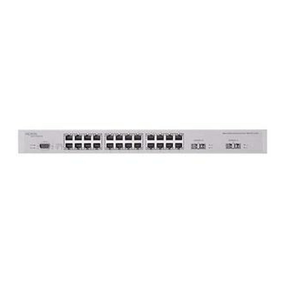
Ethernet cable and still maintain a valid link. Figure 1 shows the front panel of the Metro ESU 1800-24T-LX-DC. Figure 2 shows the front panel of the Metro ESU 1800-24T. Figure 3 on page 21 shows the front panel of the Metro ESU1800-24T-DC. -
Page 21: Figure 3 Metro Ethernet Service Unit 1800-24T-Dc Front Panel
24 Fast Ethernet ports • two GBIC fiber optic ports • the Metro ESU 1800 system The LEDs on the front panel of the Metro ESU 1800-24T (AC power supply) indicate the status of each of the: • 24 Fast Ethernet ports •... -
Page 22: Enclosure
In addition, you should allow sufficient airflow to prevent the switch from overheating. Power supply The Metro ESU 1800 Power LED is located on the unit front panel. It indicates whether the power supply is functioning properly. Cooling fans The Metro ESU 1800 contains three cooling fans. -
Page 23: Unpacking And Setting Up The Metro Esu 1800
• Four rubber feet with adhesive backing • One AC power cord for the Metro ESU 1800-24T; a DC power cord is not included with the Metro ESU 1800-24T-LX-DC or the 1800-24T-DC Figure 4 on page 24 shows the contents of shipment containing a Metro ESU 1800-24T (AC power supply). -
Page 24: Installing The Metro Esu 1800
2 = Rack-mounting hardware: • Rack-mount brackets • Screws for attaching brackets to the Metro ESU 1800 • Screws and bolts for attaching the Metro ESU 1800 to the equipment rack 3 = Rubber footpads 4 = AC power cord If any item is missing or damaged, contact your local Nortel Technical Solutions Center for replacement. - Page 25 Fachpersonal installiert und gewartet werden. Avertissement : Les unités de services Ethernet Metro 1800-24T-LX-DC et 1800-24T-DC sont destinées à une utilisation dans un environnement d'accès contrôlé uniquement. Elles ne peuvent pas être utilisées dans un endroit où des personnes non formées peuvent entrer en contact avec l'alimentation exposée.
-
Page 26: Installing The Metro Esu 1800 On A Desktop Or Shelf
Accessing the unit using a tool is controlled by the authority responsible for the location. When choosing a place to install the Metro ESU 1800, use the following guidelines: •... -
Page 27: Installing The Metro Esu 1800 In A Rack
Figure 5 Rubber feet attachment points 11284FA Installing the Metro ESU 1800 in a rack You can install the Metro ESU 1800 in a standard 19-inch electronic equipment rack or cabinet. Along with the required screws, two mounting brackets are included in the unit packaging. -
Page 28: Connecting The Power Source
19” rack. Connecting the power source You can connect the Metro ESU 1800 to an AC power source (100 to 240 VAC, 50 - 60 Hz) or a DC power source (-48V DC), depending on the model. To connect the DC power source, attach the brown power (POS. -
Page 29: Powering Up The Metro Esu 1800
Depending on the transmission speed, the 100Mb/s LED remains on. If the LEDs light as described above, your installation is successful. Contact your network administrator to verify that the Metro ESU 1800 is now connected to the network. Installing the Metro Ethernet Services Unit 1800... -
Page 30: Dealing With A Power Failure
Dealing with a power failure If the LEDs do not light as described above, contact your local Nortel Technical Solutions Center. See “How to get Help” on page 17 for more information. Caution: Before servicing this unit, turn off the power by pressing the power switch on the back of the unit to the Off (0) position. -
Page 31: 10/100Base-T Ports
Cabling requirements for the Metro ESU 1800 10/100BASE-T ports Table 1 shows the pin assignments for a 10/100BASE-T port. Table 1 Pin assignments: 10/100BASE-T port Connector Pin number Signal Input receive data + (RX+) 12345678 Input receive data - (RX-) -
Page 32: Table 2 Pin Assignments: Console Port
Cabling requirements for the Metro ESU 1800 Table 2 lists the pin assignments for the Console port. Table 2 Pin assignments: Console port Connector Pin number Signal Carrier detect (not used) Receive data (RXD) Transmit data (TXD) Data terminal ready (not used) -
Page 33: Understanding The Leds
LED indications of problems Displaying status information The Metro ESU 1800 has LEDs on its front panel that indicate the status of the internal power supply, the Metro ESU 1800 system, the link between a port and a remote network device, and the presence of activity on that link. -
Page 34: Power And Status Leds
On Self Test (POST) routine. Power and Status LEDs You use the 1800-24T with AC power supply 100- 240 VAC, 50 - 60 Hz. To power up the unit, press the power switch to the On (1) position. The power switch is located on the back of the unit. -
Page 35: Fast Ethernet Port Link/Act Leds
Flashes momentarily to represent a system reset. Power Remains on after the switch is powered up. Status Flashes while the Metro ESU 1800 loads onboard software and performs a self-test. The Status LED remains on if the system is operational. 100M Depending on the transmission speed remains on or turns off. -
Page 36: 1000Base-Lx Link/Act Leds For The 1800-24T-Lx-Dc
Each 1000BASE-LX SC type fiber optic transceiver has two green LEDs, one to indicate the status of the link between the Metro ESU 1800 and a remote network device, and one to indicate that there is activity on the port (that is, packets are being forwarded over the link). -
Page 37: Sfp Gbic Link/Act Leds For The 1800-24 And 1800-24T-Dct
Metro ESU 1800 and a remote network device, and one to indicate that there is activity on the port (that is, packets are being forwarded over the link). These LEDs are located to the left of each of the two SFP bays on the 1800-24T and 1800-24T-DC front panels (see Figure 12). -
Page 38: Led Indications Of Problems
LED indications of problems LED indications of problems Table 6 lists possible problems indicated by the LEDs on the Metro ESU 1800 and suggests corrective action. Table 6 LED problem indicators Symptom Probable cause Corrective action The Power LED is off. -
Page 39: Installing Sfp Gbic And Cwdm Sfp Gbic Modules
Installing SFP GBIC and CWDM SFP GBIC modules The Nortel* Metro Ethernet Services Unit 1800-24T provides two bays that accept SFP GBIC and CWDM SFP GBIC fiber optic modules. These modules, which operate at 1000 Mbps in full-duplex mode, allow Gigabit Ethernet ports to connect to fiber optic networks. -
Page 40: Sfp Gbic Models
Nortel* Small Form Factor Pluggable Gigabit Interface Converter (SFP GBIC) modules are hot-swappable input/output enhancement components that allow Gigabit Ethernet ports to connect to fiber optic networks. Table 7 lists the SFP GBIC modules that the ESU 1800-24T supports: Table 7 Nortel SFP GBIC models Model number Product number... -
Page 41: Table 8 Nortel Cwdm Sfp Gbic Models
Supported SFP GBIC and CWDM SFP GBIC modules Table 8 lists the CWDM SFP GBIC models that the ESU 1800-24T supports: Table 8 Nortel CWDM SFP GBIC models CWDM SFP GBIC Product number Cable length 1470nm/Gray AA1419025 40 KM AA1419033... -
Page 42: Inserting And Removing Sfp Gbic And Cwdm Sfp Gbic Modules
Inserting and removing SFP GBIC and CWDM SFP GBIC modules Inserting and removing SFP GBIC and CWDM SFP GBIC modules Warning: Fiber optic equipment can emit laser or infrared light that can injure your eyes. Never look into an optical fiber or connector port. Always assume that fiber optic cables are connected to a light source. -
Page 43: Figure 13 Sfp Fiber Optic Module Fiber Optic Cable Insertion And Removal
This allows you to remove both cable connectors as a group. Figure 13 displays the insertion and removal of the SFP fiber optic cables from a SFP module. Figure 13 SFP fiber optic module fiber optic cable insertion and removal Installing the Metro Ethernet Services Unit 1800... - Page 44 Inserting and removing an SFP GBIC fiber optic cable 317808-D...
-
Page 45: Technical Specifications
Appendix A Technical specifications This appendix lists the technical specifications for the Metro Ethernet Services Unit 1800 (Metro ESU 1800). Three models of this unit are available: • 1800-24T (AC power supply) 24 10BASE-T/100BASE-TX (UTP) ports and 2 Gigabit Ethernet (GE) trunk ports with slots for Small Form Factor Pluggable (SFP) Gigabit Interface Converters (GBICs). -
Page 46: Physical Specifications
Topic Page 1800-24T-LX-DC and 1800-24T-DC (DC power supply) interface options Translation of the safety messages Physical specifications Height: 4.4 cm (1.73 inches) Rack Units (RUs): 19 inch 1 U Width: 44.1 cm (17.3 inches) Depth: 20.8 cm (8.19 inches) Weight: 1800-24T 2.60 Kg (5.73 pounds) -
Page 47: Ac Power Supply Specifications (1800-24T Only)
EN61000-4-3, 10V/m criteria A EN61000-4-4, 2KV criteria A EN61000-4-5, 2KV criteria A EN61000-4-6, 2KV criteria A EN61000-4-11 - 30% dip 10ms criteria B - 60% dip 100ms criteria C - 95% dip 5000ms criteria C Installing the Metro Ethernet Services Unit 1800... -
Page 48: Dc Power Supply Specifications (1800-24T-Lx-Dc And 1800-24T-Dc Only)
DC power supply specifications (1800-24T-LX-DC and 1800-24T-DC only) Nominal input voltage: –40 to –60 VDC (48V Nominal) Input current: 1.5A maximum Input power Power consumption: 40 W maximum Output current: +3.3V/ 10A, +12V/ 0.5A Output power 40 W maximum Thermal output... -
Page 49: Electromagnetic Emissions
Electromagnetic: EN 55024:1998/A1:2001 Safety agency approvals UL60950-2000 Canada: CSA 22.2 #60950-00 Europe: EN60950 (CE Marking) Australia/New Zealand: AS/NZS 3260 Global: IEC 60950/EN 60950 UL 94-V1 flammability requirements for all PC boards Mexico: NOM-019-SCFI-1998 Installing the Metro Ethernet Services Unit 1800... -
Page 50: General Specifications
General specifications General specifications including supported standards, RFCs, data rate and encoding, performance, and address database sizes are listed in the subsections that follow. Standards supported IEEE 802.3 10BASE-T Ethernet (twisted-pair copper) IEEE 802.3u 100BASE-TX Fast Ethernet (twisted-pair copper) ANSI/IEEE802.3 Auto-negotiation IEEE 302.3x Flow Control IEEE 802.1p (Priority Queues) IEEE 802.1Q (VLAN Tagging) -
Page 51: Data Rate And Encoding
Reliability Minimum 222,586 hours (DC version) and 250,000 (AC version) MTBF to Bellcore TR-332 Issue 6. This is a calculated value under 0 ~ 55 degree C conditions per “Bellcore TR-332 Issue 6.” Installing the Metro Ethernet Services Unit 1800... -
Page 52: 1800-24T (Ac Power Supply) Interface Options
(40 km/70 km, 9 µm core) 1000BASE-SX SFP and CWDM SFP GBICs for the 1800-24T SFP fiber optic module transmitter electrical and optical, receiver electrical and optical, and regulatory compliance specifications are detailed in the subsections that follow. -
Page 53: General Specifications
Data output rise time: 350 ps, maximum Data output fall time: 350 ps, maximum Receiver optical characteristics Sensitivity: –18 dBm, minimum Electrical 3 dB cutoff frequency: 1500 MHz Optical center wavelength: 770 to 860 nm Installing the Metro Ethernet Services Unit 1800... -
Page 54: Environmental Specifications
EN 60825-1 EN 60825-2 Electrical safety: CLASS 3862.07 Certificate CSA 1034405 CLASS 3862.87 1800-24T-LX-DC and 1800-24T-DC (DC power supply) interface options 10BASE-T/100BASE-TX RJ-45 (8-pin modular) connectors 1000BASE-LX port Long wavelength 1300 nm duplex SC type fiber optic connector to connect devices over single mode fiber optic cable (5 km, 10 µm core) - Page 55 Output optical power: —9 µmm SMF: –9.5 ~ –3 dBm —62. 5 µmm MMF: –11.5 ~ –3 dBm —50 µmm MMF: –11.5 ~ –3 dBm Input optical power: –20 ~ –3 dBm average. Installing the Metro Ethernet Services Unit 1800...
-
Page 56: Translation Of The Safety Messages
Translation of the safety messages This section provides translations of the Caution, Danger, and Warning messages that appear within this document. 317808-D... - Page 57 Installing the Metro Ethernet Services Unit 1800...
- Page 58 317808-D...
- Page 59 Installing the Metro Ethernet Services Unit 1800...
- Page 60 317808-D...
-
Page 61: Index
24 in a rack 27 technical specifications 45 on a desktop of shelf 26 unpacking the switch 23 1800 unit installing on a desktop or shelf 26 LEDs 1800 front panel connectors status indicators 21 DB-9 31... - Page 62 Console 31 POST routine 34 Power and Console LEDs 34 power failure on the 1800 unit, dealing with 30 power supply, 1800 unit 22 powering up the 1800 unit 28, 29 publication, hard copy 17 SFP fiber optic module...