Table of Contents
Advertisement
Quick Links
Advertisement
Table of Contents

Related Manuals for Pentax W-1502N Series


Summary of Contents for Pentax W-1502N Series
- Page 1 W-1502N Series Total Station Instruction Manual...
- Page 2 Dear Customer: Congratulations! We, PENTAX are proud to present you with an W-1502N instrument. Your total station is a rugged and reliable instrument whose performance and design are not surpassed. To fully appreciate and protect your investment, we suggest that you take the necessary time to read and fully understand this manual.
- Page 3 Stored data responsibility PENTAX should not be held liability for the lost data because of wrong operation. The noise from the instrument When the instrument is working, it is normal if you hear the noise from instrument motor, it will not affect the instrument work.
- Page 4 ●Do not put the battery in the fire or high temperature condition. Explosion, damage could result. ●If use the battery which is not specified by PENTAX, there is a danger of fire, electric shock or burn. ●If use the power cable which is not specified by PENTAX, there is a danger...
- Page 5 of fire. ●If short circuit of the battery, there is a danger of fire.. ● When this product encounters disturbance of severe Electrostatic Discharge, perhaps it will have some degradation of performance like switching on/off automatically and so on. ! CAUTION ●If touch the instrument with wet hand, there is danger of electric shock.
- Page 6 6) The manufacturer assumes no responsibility for damage caused by wrong transport, or action due to connecting with other products. Safety Standards for Laser W-1502N series adopts the safe and visible laser on the basis of “Specification Standard of radiant products” (FDA CDRH.21CFR Part 1040.10 and 1040.11) and “Safety of laser products –...
- Page 7 Note for Safety ! WARNING ● Never point the laser beam at other’s eyes, it could cause serious injury. ● Never look directly into the laser beam source, it could cause permanent eye damage. ● Never stare at the laser beam, it could cause permanent eye damage. ●...
-
Page 8: Table Of Contents
CONTENT 1. Nomenclature and Functions......... 1 1.1 Nomenclature............ 1 1.2 Keyboard............3 1.3 Main menu............4 1.3.1 Basic Measurement........... 4 1.3.2 STD Measurement(Optional)........5 1.3.3 Instrument Setup..........5 1.3.4 About............6 1.3.5 Professional field software........6 1.3.6 Convenient panel..........6 1.4 Shortcut key............7 1.5 Touch screen calibration...........8 1.6 Battery............ - Page 9 4.3.1 Horizontal angle(right angle) and vertical angle measurements..22 4.3.2 Horizontal angle switch between right and left....23 4.3.3 Setting horizontal angle with the “L.Angle” key....24 4.3.4 Setting horizontal angle with the “S.Angle” key....25 4.3.5 Setting “vertical angle and percent grade” mode with the “V/%” key...............
- Page 10 ..............82 Appendix II: Correction for refraction and earth curvature....84 Appendix III: Assembling and disassembling for three-jaw tribrach..85...
-
Page 11: Nomenclature And Functions
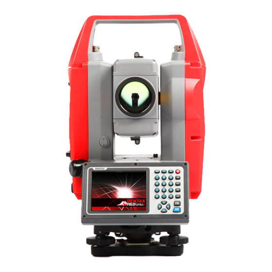
1. Nomenclature and Functions 1.1 Nomenclature Handle Handle Optical sight Objective Instrument height Keypad Touch Circular level Touch pen... - Page 12 Battery clamp Vertical Eyepiece clamp knob Vertical tangent knob Plate Battery clamp Horizontal clamp knob Horizontal tangent Tribrach USB port clamp...
-
Page 13: Keyboard
1.2 Keyboard W-1502N series is equipped with two color touch screens and alphanumeric keypad, operation by both touching screen and pressing keyboard is possible. Do not touch the screen with ball-pen, pencil or other sharp thing to avoid damage on instrument. - Page 14 by program screen ▲▼ Navigation key Control the focus bar within the screen and the entry bar within a field ⓛ Power key Turn on/off the instrument...
-
Page 15: Main Menu
1.3 Main menu Function introduction Display After initiating the instrument the screen will go to present “Welcome Interface” which shown right. PENTAX Survey consists of several functions, that is, “BSC Measure(Basic Measurement ) ”, “STD Measure ( ) Standard Measurement ”, “Engineering Surveying(... - Page 16 Distance Offset Measurement, Plane Offset Measurement, Column Offset Measurement. Besides, basic measurement is also used for performance testing for total station. 1.3.2 STD Measurement(Optional) Function introduction Display STD measurement function is used to resolve calculate applied measurements during conventional surveying. contains “project management”,...
-
Page 17: Instrument Setup
1.3.3 Instrument Setup Function introduction Display Instrument setup function is mainly applied instrument settings, instrument calibration and generation management instrument constant. It is made up of a series of functions such as “compensator linear correction”, “compensator zero correction”, “horizontal axis error correction”, “index... -
Page 18: Convenient Panel
W-1502N provides professional surveying and cartography program, such as “PENTAX FieldGenius”. In fact, PENTAX W-1502N supports more third-party softwares. 1.3.6 Convenient panel Function introduction Display Click 【 ★】 key to enter into convenient panel. Electronic bubble function on this panel is used for dynamic display of electronic bubble during leveling up.Furthermore,functions like settings... - Page 19 Turn on/off backlight of key panel in face right FUNC+TAB position CTRL+ESC Enter boot menu CTRL+TAB Start touch screen calibration FUNC+CTRL Turn on/off soft keyboards FUNC+↑ Increase backlight brightness of LCD FUNC+↓ Decrease backlight brightness of LCD FUNC+← Turn on/off LCD display in face left position Turn on/off LCD display in face right position FUNC+→...
-
Page 20: Touch Screen Calibration
1.5 Touch screen calibration When you operate on the screen, if your device isn’t responding to you taps, you may need to recalibrate your screen. In any picture, press the combination key “CTRL+TAB” so as to enter into touch screen calibration. The calibration process is shown in the figure below. -
Page 21: Replace And Mount Battery
NOTE: 1. The battery’s working time will be affected by many factors, such as ambient temperature, recharging time, recharging and discharging times. So we suggest the users recharge the battery full or prepare several full batteries before operation. 2. The battery symbol only indicates power capability for current measurement mode. -
Page 22: Recharge Battery
3) Push one battery case towards lower one box into the end,, clockwise turn the round battery clamp 90°to mount the lower battery case 1.6.3 Recharge battery 1)With battery power contactors touch with charger contactor, put battery into charger case by bayonet lock 2)Plug the charger on 100V/240V power supply.The red lamp becomes lighting,which indicates recharging.If interval-time is longer,the connector isn’t fixed well. -
Page 23: Usb Connection
1.7 USB connection ● The file in the instrument could be read through ActiveSync software by USB cable. ● External memory stick could be used by USB Host connector. The file in the external memory stick could be read in the instrument interface. 1)Open the cover of USB which behind the display panel;... -
Page 24: Guide Light(Optional)
1.8 Guide light(Optional) Guide light is optional in W-1502N series total station. It is mainly used to stake out. The Surveyor could adjust the position of prism and station through the guide light color. It will be faster to set the prism. -
Page 25: Preparation Before Measurement
2. Preparation before Measurement 2.1 Setting up the instrument (1) Set up the tripod first: extend the extension legs to suitable lengths and tighten the screws on the legs.Make sure the legs are spaced at equal intervals and the head is approximately level. - Page 26 (3) Accurate Levelling-Up with Electronic Level on the screen It is convenient for W-1502N series to level-up with electronic level, especially when it is difficult to observe the circular level and plate level. Firstly,press the key 【★】 to turn on the electronic bubble as shown in left figure.On...
- Page 27 【XONYOFF】just compensate X axis 【XYOFF】 don’t compensate X axis and Y axis 【A.OFF】 don’t compensate X axis and Y axis,and turn off the popup function of electronic bubble. In PENTAX FieldGenius software, the Level display is always shown as left figure.
-
Page 28: Centering
2.3 Centering 2.3.1 Centering with Laser Plummet Press the key 【★】 to enter into the display as shown in the left figure. Operation Steps: ①Click the “target” button,and you can turn on laser plummet and set it as three levels of brightness.Thus,that laser emits downwards can be seen. -
Page 29: Instrument Settings
3 Instrument settings Instrument settings software is applied for settings and calibration of instrument,generation and management of instrument constant.It is made up of a serie of functions such as “compensator linear correction”, “compensator zero correction”, “horizontal axis error correction”, “index correction”, “instrument settings”,... - Page 30 NOTE: This password is open for all users, current configuration settings can be checked here, but not be adjusted. If you want to adjust these settings, please contact local distributer or PENTAX company.
-
Page 31: Setting The Measure Condition
3.1.1 Setting the measure condition Opereation: 1. The distance measurement mode will be: Fine, Coarse, Repeat Fine, Average Fine, Tracking. 2. Tilt correction mode will be: HV, V, NO, Always off. 3. Collimator correction mode will be: Yes or No. correction mode will... -
Page 32: Setting Parameters Of Communication Ports
3.1.3 Setting parameters of communication ports left shows,click “Other Setup”,you activate bluetooth(BT) guidelight(GL),and set parameters of “Bluetooth Port” and “Phy Port”. 3.1.4 Instrument parameters review Click “Data Monitor” used for reviewing the setting parameters. -
Page 33: Illumination Settings
3.2 Illumination settings Press the 【 ★ 】 button and click “Target” and “Battery” keys in order to with illumination settings including “Cross Light”, “Guide Light”,and“Laser Point”. Cross Light: Click this item to turn on the reticle illumination, and move the slipping button to adjust reticle illumination. -
Page 34: Basic Measurement Program
4. Basic measurement program 4.1 Run the program “Basic Measurement” Current parameters Function Measurement mode 4.2 Basic measurement screen introduction The function keys display in the lower left corner of screen,and they vary from one measurement mode to another.There are some function keys under every measurement mode being listed in the following table. -
Page 35: Angle Measurement Mode
OCC PT Set the coordinate of instrument station S.BS Set the coordinate of a backsight point Setup Set instrument height and target height Line Start traverse surveying Offset Start offset measurement(ANG.Offset,DIST Offset,PLANE Offset,CYL.Offset) function Coor Set displayed coordinate order as NEZ or ENZ Order Save Save coordinate of instrument station or not... -
Page 36: Horizontal Angle Switch Between Right And Left
②Set horizontal angle as 【S.Zero】 【OK】 zero for target A.Click the “S.Zero” button,and choose “OK” popup dialog box. ③Collimate the second Collimate first target B,and the horizontal angle vertical angle will display screen instrument. 4.3.2 Horizontal angle switch between right and left Make sure the operation is under angle measurement mode. -
Page 37: Setting Horizontal Angle With The "L.angle" Key
②switch 【 L/RAngle horizontal 】 angle between left and right by Clicking “L/R ※1 Angle” key ※1 Left angle or right angle will be switched in turn every time you click the “L/R Angle” key. 4.3.3 Setting horizontal angle with the “L.Angle” key Make sure the operation is under angle measurement mode. -
Page 38: Setting Horizontal Angle With The "S.angle" Key
③Collimate target point used for Orientation. ※1 ④Click “unclock” key to deactivate 【Unlock】 function locking horizontal angle.Then the screen will return normal angle measurement mode,and meantime horizontal angle will be set as locked angle. ※1 Click “Cancel” key before it returns to Previous mode. 4.3.4 Setting horizontal angle with the “S.Angle”... -
Page 39: Setting "Vertical Angle And Percent Grade" Mode With The "V/%" Key
②Click “S.Angle” key, 【S.Angle】 and a dialog box will be ejected, as is showed in the right figure. input ③Input horizontal angle horizontal you need. angle ※ 1 Such as:232°26'26" ④With data entry complete , click “Enter” 【Enter】 key,and angle measurement after orientation will go on. -
Page 40: Carrying Out Angle Retesting With The "Repeat" Key
①Make sure operation is under angle measurement mode. ②Click “V/%” key. 【V/%】 ※1 ※1 Vertical angle and percent grade will be switched in turn every time you click “V/%” key. 4.3.6 Carrying out angle retesting with the “Repeat” key This program is applied for adding up angle retesting values,displaying the sum and the average of all observed values,and meantime recording the number of observations. - Page 41 Operation steps Keys Display ①Click “Repeat” 【Repeat】 key,and activate angle retesting function.
- Page 42 ②Collimate first Collimate A target A. ③Click “S.Zero” 【S.Zero】 key,and set horizontal angle as zero. ④Collimate the second target using Collimate B horizontal clamp and tangent part.
- Page 43 ⑤Click “L.Angle” key. 【L.Angle】 ⑥Collimate first target A again using Collimate A horizontal clamp and again tangent part. 【Unlock】 ⑦Click “Unlock” key. ⑧Collimate the second target B again using horizontal clamp and tangent part. Collimate B ⑨Click “L.Angle” again key.And then 【L.Angle】...
-
Page 44: Distance Measurement Mode
Hm: the average of multiple observed values 4.4 Distance measurement mode 4.4.1 Distance measurement and measuring mode setting Operation steps Keys Display ①Collimate the centre Collimate of prism. - Page 45 ②Click “M.Dist” key to 【M.Dist】 enter distance measurement mode, and then the system will carry out measurement based previous setting mode. ③Click “Mode” key to 【Mode】 activate setting function distance measurement mode. Take “Loop Fine” as example here. Fine: single fine measuring mode N Fine: n times fine...
-
Page 46: Fine/Tracking Distance Measurement
※ 2 Click “M.Ang” key to return angle measurement mode. 4.4.2 Fine/Tracking distance measurement When you preset the measuring times, the instrument will carry out distance measurement and display the average distance according to the setting times. If you preset single observation, the average distance won’t be displayed. -
Page 47: Accurate Measurement And Track Mode
③Click “Enter” key, collimate the centre of prism,and then system will carry out measurement based on previous setting. ※1 ※1 Click “M.Ang” key to return angle measurement mode. 4.4.3 Accurate Measurement and Track mode Accurate Measurement mode:it’s a normal measurement mode. Track mode:Track mode takes less time than accurate measurement.It is mainly applied for setting-out survey and useful for tracking moving target. -
Page 48: Exchange Of Distance Units
①Collimate the centre Collimate of prism. prism ②Click “Mode” key to 【Mode】 activate setting function distance measurement mode.And this mode is set as “Track”. ③Click 【Enter】 “Enter” key,collimate centre of prism,and the system will carry out measurement based on previous setting. 4.4.4 Exchange of distance units Change distance unit on the screen of distance observation. -
Page 49: Distance Stake Out Measurement
①Click “m/ft” key. 【m/ft】 ②Changed distance unit will display in the upper right corner. ※1 ※1 Distance unit will be exchanged among meter,american feet and international feet every time you click “m/ft” key. 4.4.5 Distance stake out measurement This function can display the difference between measured distance and preset distance. - Page 50 ①Click 【Setout】 “Setout” under distance measurement mode. ②Select distance measurement mode (SD,HD,VD)to be set out, input required data and then click “Enter” key. ※1 ③Start setting out. ※1 First of all,a prompt that reminds you to input SD to be set out is displayed in the popup dialog box.
-
Page 51: Remote Elevation Measurement(Rem
4.4.6 Remote Elevation Measurement ( REM ) The Remote Elevation program calculates the vertical distance (VD) of a remote object relative to ground. When using a prism height, the remote elevation measurement will start from the prism (reference point). If no prism height is used, the remote elevation will start from any reference point in which the vertical angle is established. - Page 52 ②Select 【with PH】 “with PH” button with stylus. ③Input the prism height Input prism following PH. height ④Collimate the centre P Collimate of prism. prism ⑤Click “M.Dist” key to 【M.Dist】 start measuring. ⑥Horizontal distance between instrument prism will shown.
- Page 53 ⑦Click “Continue” key, 【 Continue 】 and position of prism is locked, that means reference point confirmed. ⑧Collimate target K and 【 Collimate click “Continue”, K】 vertical distance (VD) will be shown. ※1) ※1)Click “Exit” key to finish REM. 2)without prism height input...
- Page 54 Operation steps Keys Display ①Select 【None PH】 “None PH” button with stylus. ②Collimate the ground Collimate point. prism ③Click “M.Dist” key to start observing. ④Horizontal 【M.Dist】 distance between instrument and prism will be shown. ⑤Click “Continue” key, 【 Continue 】 and position of ground point G is locked that means reference point is...
- Page 55 ⑥Click “Continue” key. 【 Continue 】 ⑦Collimate remote Collimate target K.Vertical target distance(VD) will shown. ※1) ※1) Click “Exit” to finish REM.
-
Page 56: Missing Line Measurement (Mlm)
4.4.7 Missing Line Measurement (MLM) The Missing Line Measurement program calculates the horizontal distance (dHD), slope distance (dSD) and elevation (dVD) between two target prisms. The instruemt can accomplish this in two ways: 1.MLM Method (A-B, A-C): Measurement is A-B, A-C, A-D, ..2.MLM Method (A-B, B-C): Measurement is A-B, B-C, C-D, .. - Page 57 Operation steps Keys Display ①Under distance measurement, click 【MLM】 “MLM” key to activate Missing Line Measurement. ②Select method (A-B, A-C) with stylus. ③Collimate prism A,click “M.Dist” key. 【M.Dist】 Horizontal distance between instrument and prism A will be shown.
- Page 58 ④Collimate prism 【M.Dist】 B,click “M.Dist” key. ⑤Click “Continue” key,then horizontal distance(dHD), elevation 【Continue difference(dVD) 】 slope distance (dSD) between prism A and prism B will display. ※1) ⑥In order to calculate the horizontal distance between points A and C,collimate prism C,and 【M.Dist】...
-
Page 59: Line-Height Measurement
⑦Click “Continue” key,then dHD, dVD and 【Continue dSD between prism A 】 and prism C will be shown. ※1)Click “Exit” key to return main menu. ●Procedure of MLM Method (A-B, B-C) is completely same as Method (A-B, A-C) Method. 4.4.8 Line-height Measurement This function is applied for measuring and determining a height of line(like electric wire)above ground which is hard to reach. - Page 60 Operation steps Keys Display ①Under distance measurement mode, 【LHM】 click “LHM” activate line-height measurement program. ②Select “With PH” With PH button with stylus.
- Page 61 ③Click “Setup” key to input instrument 【Setup】 height(IH) prism height(PH).After that click “Enter” key. ④Collimate prism click “Measure” key, distance 【Measure】 measurement begins. After that click “Continue” key. ⑤Collimate prism click “Measure” key, 【Measure】 distance measurement begins.
- Page 62 ⑥After 【Continue measurement 】 click “Continue” key. ⑦Collimate point L on overhead line. screen displays measuring data collimating L. VD : Vertical distance between A and L. HD:Horizontal distance between instrument and L. Off:Horizontal distance between A and L. ⑧Click “Continue” key which used measuring...
- Page 63 ⑨Collimate ground Collimate point G by screwing vertical tangent part. ⑩Click “Continue” key again, and then height 【Continue overhead line(LH) 】 horizontal distance(Off) will ※1)~※3) display. ※1) Click “X” key to end measurement. ※2) Click “VH” key to return operation step⑦.
-
Page 64: Coordinate Measurement Mode
4.5 Coordinate Measurement Mode 4.5.1 Setting coordinate of occupied point After input coordinate of occupied point(instrument location), unknown point coordinate will be measured and displayed with this program. Operation steps Keys Display ①Click “M.Coor” key to 【M.Coor】 enter coordinate measurement mode. ②Click “OCC PT”... -
Page 65: Setting Backsight Point
③Input coordinate occupied point from N to Z. ④Finishing data entry,click “Enter” key 【Enter】 and return coordinate measurement interface. 4.5.2 Setting backsight point Operation steps Keys Display ①Click “S.BS” key to set 【S.BS】 backsight point. - Page 66 ②Input coordinate 【Enter】 backsight point and click “Enter” key. ③A dialog box is ejected as figure shows. ④Collimate backsight point, click “Yes” key. And then the system will define backsight 【Yes】 azimuth angle which displays in the upper left corner coordinate measurement screen.
-
Page 67: Setting Instrument Height And Prism Height
4.5.3 Setting instrument height and prism height Coordinate measurement must be based on instrument height and prism height, thus coordinate of unknown point can be calculated easily and directly. Operation steps Keys Display ①Click “Setup” key. 【Setup】 ②Input instrument Input IH height (IH)and prism... -
Page 68: Operation Of Coordinate Measurement
4.5.4 Operation of coordinate measurement With coordinate of occupied point, backsight azimuth angle, Instrument height and prism height set up,you can directly calculate coordinate of unknown point. Operation steps Keys Display ①Set coordinate occupied point instrument height/prism height. ※1) ②Set backsight azimuth angle. -
Page 69: Traverse Surveying
④Click “M.Coor” key to 【M.Coor】 finish operation. ※4) ※1)If don’t input coordinate of occupied point, previous coordinate of occupied point is set as default. If don’t input instrument height and prism height, the previous is set as default too. ※ 2)refer to “4.3.4 Setting horizontal angle with the S.Angle key” or “4.5.2 Setting backsight point”。... - Page 70 Set coordinate of occupied point p0 and azimuth angle from point P0 to known point A. Operation steps Keys Display ①Click “Line” key. 【Line】 ②Click “Save” key with 【Save】 stylus.
- Page 71 ③Click “Setup” key to reset instrument height 【Setup】 and prism height. And then click “Enter” key. ④Collimate prism target point P1 where 【Measure】 instrument will transferred. Meantime click “Measure” key. ⑤Click “Continue” key 【 Continue and coordinate of Point 】 P1 displays in the lower left corner of screen.
- Page 72 ⑥Click “Save” key. Coordinate of P1 be ascertained and it will return main 【Save】 menu.At last power off and transfer instrument P1(transfer prism from meantime). ⑦After instrument established in P1,enter into traverse surveying coordinate measurement and select “Call” button with stylus.
-
Page 73: Offset Measurement Mode
4.5.6 Offset Measurement Mode There are four kinds of Offset Measurement Modes: Angle Offset Measurement Distance Offset Measurement Plane Offset Measurement Column Offset Measurement 1) Angle Offset Measurement This program is used to measure the point where it’s difficult to set prism. Place the prism at the same horizontal distance from the instrument as that of point A0 to measure. - Page 74 elevation difference(VD) will change too.But if collimate A0 with the second method,vertical angle is locked in the direction where prism is located and can’t range from up-and-down movement of telescope. Operation steps Keys Display 【Offset】 Click “Offset” key. Click “ANG.Offset” key in ejecting dialog box.
- Page 75 Collimate prism Collimate P,and click prism P “Measure” key. ⑤Collimate target Collimate with horizontal clamp and tangent part. Click “Continue” key.Then slope distance,horizontal distance 【 Continue elevation difference 】 from instrument to A0 and coordinate of A0 will be shown. ※1),※2) ※1) Click “Setup”...
- Page 76 ●When measuring coordinate of ground point A1,set instrument height and prism height. ●When measuring coordinate of point A0,set instrument height only(Prism height is set as 0). ●Refer to “4.5.1” to set coordinate of occupied point. Operation steps Keys Display 【 DIST Click “DIST Offset”...
- Page 77 ③Collimate prism and 【Measure】 click “Measure” key. ④Click “Continue” key,and result displays 【 Continue with the correction of 】 offset distance. ※1),※2) ※1) Click “Setup” key to set instrument height and prism height. ※2) Click “Exit” key to finish Distance offset measurement. 3) Column Offset Measurement It is possible to measure circumscription point(P1) of column directly,the distance to the center of column(P0),coordinate and direction angle can be...
- Page 78 ● Refer to “4.5.1” to set coordinate of occupied point. Operation steps Keys Display 【CYL.Offse Click “CYL.Offset” key. t】...
- Page 79 ②Collimate center(P1) column 【Measure】 surface,and then click “Measure” key. ③Collimate left 【 Continue point(P2) column 】 surface,and then click “Continue” key. ④Collimate right point(P3) column surface.
- Page 80 Click “Continue ” key,and relational values between 【 Continue instrument 】 center column(P0) can be calculated and shown. ※1),※2) ※1) Click “Setup” key to set instrument height and prism height. ※2) Click “Exit” key to finish column offset measurement. 4) Plane Offset Measurement Measuring will be taken for the place where direct measuring can not be done,for example distance or coordinate measuring for an edge of a plane.Three random points(P1,P2,P3) on a plane will be measured at first in...
- Page 81 【 PLANE Click “PLANE Offset” Offset】 key. ②Collimate prism 【Measure】 P1,and click “Measure” key. ③Collimate prism 【Measure】 P2,and click “Measure” key.
- Page 82 ④Collimate prism 【Measure】 P3,and click “Measure” key. ⑤Click “Continue” key calculate relational 【 Continue values between 】 collimation axis plane. ※1) ※1)Click “Setup” key to set instrument height and prism height. ●If the three observing points can’t determine a plane,the system will display error message.Thus observe the first point once again.
-
Page 83: About
4.6 About Operation: 1. Click “about” icon on desktop. 2. Press “Exit” to return the basic measurement. -
Page 84: Check And Adjustment
4. Compare length of the instrument’s testing line again with a certain standard testing line . 5. If the difference is over 5 mm after the preceding operations, it is necessary to reset the instrument constant . 2) Adjustment About instrument constant setting, you must contact PENTAX distributor to do that. -
Page 85: Plate Level And Circular Level
5.2 Plate Level and Circular Level 5.2.1 Plate Level 1) Check 1. Mount the instrument on a stable device (as tripod , adjusting device ),and fix it. 2. Level the instrument until the plate level is parallel to a line linking leveling foot screws A and B, then adjust the two screws to center the air bubble. -
Page 86: The Optical Sight
Note: Be careful when adjusting the three screws, and the tightening tension is identical for them. 5.3 The Optical Sight 1) Check 1. Mount the instrument on a tripod and fix it. 2. Set a cross mark target which apart from the instrument about 50m. -
Page 87: Vertical Cross-Hair On Telescope
2) Adjustment When a centre part where a cross intersection and the laser mark look the brightest shifts by 0.5mm or more (at the instrument height 1.5m), it is necessary to adjust it. A repair engineer does this adjustment. Please contact the LINERTEC dealer. 5.5 Vertical Cross-hair on Telescope 1) Check (1) Set the instrument up the tripod and carefully level it. - Page 88 NOTE: 1)After the adjustment of cross-hair, please check the collimation error and vertical index error. 2) Refer to the chapter “5.9 EDM Optical Axis and the Telescope Sighting Axis Error” to check the axis. At last check the collimator error again.
-
Page 89: Horizontal Collimation Error C
5.6 Horizontal Collimation Error C If the telescope’s sight line isn’t perpendicular to the horizontal axis, the collimation error will appear. The assembling, transportation and operation will cause this error. If the collimation error isn’t over the permitted range, with the program the instrument can correct this collimation error. -
Page 90: Vertical Index Error
4. The software will calculate the new collimation error and vertical index error automatically. 5. Tap “Enter” to save the new values, or tap “Cancel” to use old values. Note: The adjustment can be performed by the program when C<30″, if C>30″, adjust the reticle. - Page 91 Please adjust the reticle of telescope and correct the collimation error before this operation. (1) Mount the instrument at the tripod or a stable device and level it accurately, then turn on the instrument. (2) Aim at the cross-hairs of collimator or the obvious target at a distance, VA should be about ±10°.
-
Page 92: Edm Optical Axis And The Telescope Sighting Axis Error
1/5 of red mark diameter, adjustment is unnecessary. 2)Checking (For W-1502N series) (1) Install the instrument at the tripod or a stable device and level it accurately, then power on the instrument. -
Page 94: Specifications
6. Specifications W-1502N series Telescope Length 156mm Image Erect Magnification 30× Aperture 45mm 1°30′ Field of view Minimum focus 1.0m Angle measurement Reading system Absolute encoder Circle diameter 79mm Angle unit 360degree/400gon/6400mil, selectable Minimum display 0.5″/1″/5″,selectable 0.1mgon/0.2mgon/1mgon, selectable Detecting mode... - Page 95 Fine mode: 1.5 s Rapid mode: 0.9s Tracking mode: 0.5s Prism typ.1.0-1.5s Reflective sheet/Rp60 typ.1.5s Reflectorless typ.1.5-5s,max.20s ℃/℉, selectable Temperature unit Pressure unit hPa/mmHg/inchHg, selectable Temperature input range -30℃ to +60℃ (1℃ steps) Pressure input range 510hPa to 1066hPa(1hPa setps) Prism constant condition -99.9mm to +99.9mm Refraction and earth curvature correction...
- Page 96 battery Voltage 7.4V DC Continuous operation time About 10 hours(single distance measurement every 30 seconds) Chargers FDJ6-Li(100V to 240V) ℃) Approx. 4 hours Charging time (at +20 Application programs Data collection/Stake out/Resection/REM/MLM/Point to line AREA/Z coordinate/OFFset/3D Road/Traverse adjustment Tape measurement/section/axis positioning measurement Others ARM9 Core Memory...
-
Page 97: Standard Components
8. Standard components ● Carrying case 1 each ● Instrument 1 each ● Battery 2 each ● Charger 1 each ● Adjusting pins 2 each ● Cleaning cloth 1 each ● Cleaning brush 1 each ● Screwdriver 1 each ● Wrench 2 each ●... -
Page 98: Appendix I: Atmospheric Correction Formula And Chart(Just For Reference)
Appendix I: Atmospheric correction formula and chart(Just for reference) Factory setting: temperature: 20℃, pressure:1013hpa, 0ppm The correction: Kpt=274.417-0.2905*p/(1+0.0036*t) Where: p--Pressure value (hPa) t--Temperature value (℃) Kpt--Atmospheric correction (ppm) Example: t=20℃, p=1013hpa, L0=1000m. Then: Kpt=0ppm L=L 0 (1+Kpt)=1000×(1+0×10 -6 )=1000.000m The atmospheric value is obtained easily with the atmospheric correction chart. - Page 100 Appendix II: Correction for refraction and earth curvature Considering the correction of refraction and earth curvature for distance measurement, the formula for slope distance, horizontal distance and vertical distance applied in the instrument are as followings: The conversion formula for horizontal and vertical distance is as follows when correction for refraction and earth curvature is not applied: VD=SD ∣SIN§∣...
- Page 101 NOTE: These designs, figures and specifications are subject to change without notice. We shall not be held liable for damages resulting from errors in this instruction manual.