Table of Contents
Advertisement
Quick Links
TOTAL STATION
W-800
BASIC INSTRUCTION
MANUAL
PENTAX Industrial Instruments Co., Ltd.
2-5-2 Higashi-Oizumi
Nerima-Ku, Tokyo 178-8555, Japan
Tel. +81 3 5905 1222
Fax +81 3 5905 1225
E-mail: international@piic.pentax.co.jp
Website: www.pentax.co.jp/piic/survey
www.pentaxsurveying.com
SERIES
Ahead of Vision
Advertisement
Table of Contents

Related Manuals for Pentax W-800 Series


Summary of Contents for Pentax W-800 Series
- Page 1 TOTAL STATION SERIES W-800 BASIC INSTRUCTION MANUAL PENTAX Industrial Instruments Co., Ltd. 2-5-2 Higashi-Oizumi Nerima-Ku, Tokyo 178-8555, Japan Tel. +81 3 5905 1222 Fax +81 3 5905 1225 E-mail: international@piic.pentax.co.jp Website: www.pentax.co.jp/piic/survey www.pentaxsurveying.com Ahead of Vision...
- Page 3 This Basic Instruction Manual contains the basic operation procedures and precautions on W-800 series hardware. W-800 series is an open platform product and you can enjoy variety of application software on it. Regarding the operations of application software, please refer to their respective manuals.
-
Page 4: Precautions Regarding Safety
PRECAUTIONS REGARDING SAFETY Safety precautions (Must be followed) The following items are intended to prevent possible injury to the user or other people and/or damage to the instrument before it occurs. These safety precautions are important to the safe operation of this product and should be observed at all times. Distinctive displays The following displays are used to distinguish precautions by the degree of injury or damage that may result if the precaution is ignored. - Page 5 • Electro-Magnetic Compatibility (EMC): This instrument complies with the protection requirement for residential and commercial areas. If this instrument is used close to industrial areas or transmitters, the equipment can be influenced by electromagnetic fields. • Do not use this product in a coal mine, in a location where there is coal dust, or near flammable material as there is a risk of explosion.
-
Page 6: Usage Precautions
(3R) laser product.) [EDM axis] The W-800 series EDM is the red visible laser beam and the beam diameter is very small. The beam is emitted from the objective center and the base plate center hole. The EDM axis is designed to coincide with the telescope sight axis (but both axes may deviate slightly because of intense temperature changes and a long time lapse). - Page 7 [Battery & charger] • Do not use any battery or battery charger that is not approved by Pentax as it entails a risk of damaging the instrument.
- Page 8 out as the time a battery lasts on one full charge differs depending on conditions of ambient temperature, and the measurement mode of the instrument. • Confirm the battery level remaining before operating. [Auto focus] The Auto focus mechanism is very precise but will not function under every condition. Focusing depends on brightness, contrast, the shape and size of the target.
- Page 9 [Checks and repairs] • Always check the instrument before beginning work and check that the instrument is maintaining the proper level of precision. Pentax bears absolutely no responsibility for damages due to survey results obtained from surveys conducted without an initial instrument check.
-
Page 10: Table Of Contents
CONTENTS PRECAUTIONS REGARDING SAFETY SAFETY PRECAUTIONS (MUST BE FOLLOWED) USAGE PRECAUTIONS 1. BEFORE USING THE INSTRUMENT 1.1 NAMES OF PARTS 1.2 UNPACKING AND PACKING 1.3 STANDARD EQUIPMENT 1.4 ATTACHING AND CHARGING THE BATTERY 1.5 INSERTING / REMOVING SD CARD 1.6 INSERTING / REMOVING CF CARD 1.7 CONECTING USB CABLE 1.8 INTERNAL MEMORY 2. - Page 11 5. SPECIFICATIONS 5.1 NX MODELS 5.2 EX MODELS 6. APPENDIX 6.1 ATMOSPHERIC CORRECTION 6.2 hpa AND mmHg CONVERSION TABLE 6.3 ERROR WHEN NO ATMOSPHERIC CORRECTION IS MADE 6.4 ATMOSPHERIC REFRACTION AND EARTH CURVATURE CORRECTION 6.5 DISTANCE RANGE 7. NOTICE TO THE USER OF THIS PRODUCT...
-
Page 12: Before Using The Instrument
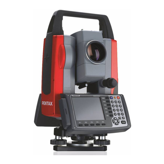
1. BEFORE USING THE INSTRUMENT 1.1 Names of parts Top handle Collimator Focus ring Power focus key AF buton Eyepiece ring Instrument height mark Eyepiece Battery latch Laser indicator Battery pack Circulator vial Telescope tangent screw CF card slot Telescope clamp screw Display panel Clamp screw Key board... -
Page 13: Unpacking And Packing
1.2 Unpacking and packing [Unpacking the Instrument from the case] Set the case down gently with the lid facing upwards. Open the latches while pressing down on the lock (safety mechanism) and open the lid of the case. Remove the instrument from the case. [Packing the Instrument in the case] Make sure the telescope is fairly level and lightly tighten the telescope clamp screw. -
Page 14: Attaching And Charging The Battery
1.4 Attaching and charging the battery [Removing the Battery] Turn the Battery latch anticlockwise and remove the battery pack. Lift up the battery pack and remove it from the instrument. • Be absolutely sure to turn the power off when removing the battery pack as removing the battery pack while the power is still on may result in damage to the instrument. - Page 15 [Charging the battery] • The battery BP02 is not charged at our factory shipment. It must be changed before use. • For BP02 charge, use the special BC03 charger. [Connection of code] Insert the output plug of the power supply code in Jack of the AC adaptor. Insert the output plug of the AC adaptor in Jack of the charger.
- Page 16 [Display panel] Power supply lamp (red): Turns on when the power supply is turned on. Charge lamp (green):Turns on while charging and turns off when the charge is completed. Discharge lamp (yellow): Turns on when you push the discharge button. Turns off when the discharge is completed.
-
Page 17: Inserting / Removing Sd Card
1.5 Inserting / removing SD card • Be sure to turn the instrument’s power off before inserting or removing the SD card. Inserting SD card 1) Open the Slot cover 2) Insert the SD card into the slot. (The side with terminal should face the instrument and the cut-off corner should be up). -
Page 18: Inserting / Removing Cf Card
1.6 Inserting / removing CF card • Be sure to turn the instrument’s power off before inserting or removing the CF card. Inserting CF card 1) Unlock the CF card slot cover by pressing ‘CF OPEN’ button, then, open the cover. 2) Carefully insert the CF card into the Slot until the Inject button pops out. -
Page 19: Conecting Usb Cable
Removing CF card 1) Unlock the CF card slot cover by pressing ‘CF OPEN’ button, then, open the cover. 2) Press the Inject button so the CF card pops out. 3) After the CF card is removed, close the Slot cover completely. 1.7 Connecting USB cable •... -
Page 20: Internal Memory
1.8 Internal memory W-800’s internal memory stores data in a folder named DiskOnChip in /MyComputer. Be sure not to connect W-800 and a PC with USB cable and transfer the stored files in the DiskOnChip or delete the file using the PC. -
Page 21: Display And Keyboard
2. DISPLAY AND KEYBOARD 2.1 Display and keyboard Laser and ESC key Illumination key Electronic vial key Power key Alphanumeric and +/- key ENT key Function key Cursor control key 2.2 Operation keys Description Used to turn ON/OFF power supply Used to return to previous screen or cancels an operation. -
Page 22: Detaching / Attaching Stylus Pen
2.3 Detaching / attaching Stylus pen Stylus pen is attached behind the LCD unit. Touch panel input Selection of functions can be done by touching the display with Stylus pen. Do not touch the display with any things such as fingertips or pen point. Otherwise it may cause malfunction or damage to the display. -
Page 23: Alphanumeric Input
2.4 Alphanumeric input The point name is inputted by the Alphanumeric keys as following. Letter under Key Letter & Figure order to input [@][.][_][-][:][/][0] PQRS [P][Q][R][S][p][q][r][s][1] [T][U][V][t][u][v][2] WXYZ [W][X][Y][Z][w][x][y][z][3] [G][H][I][g][h][i][4] [J][K][L][j][k][l][5] [M][N][O][m][n][o][6] [ ][?][!][_][ ][^][I][&][7] [A][B][C][a][b][c][8] [D][E][F][d][e][f ][9] [.][,][:][;][#][(][)] [+/-] [+][-][*][/][%][=][<][>] 2.5 LD POINT, Laser pointer How to activate/terminate the laser beam emission differs depending on application software. -
Page 24: Preparation For Surveying
3.PREPARATION FOR SURVEYING 3.1 Centering and leveling of the instrument [Setting up the instrument and the tripod] Adjust the tripod legs so that a height suitable for observation is obtained when the instrument is set on the tripod. Hang the plumb bob on the hook of the tripod, and coarse center over the station on the ground. -
Page 25: Laser Plummet
3.2 Laser plummet Turn on the laser plummet function. How to activate/terminate the laser beam emission differs depending on application software. For exact method of activating/terminating laser beam emission, refer to the instructions in the manuals of respective software. The brightness adjustment step of the laser is 10 steps. Match the position by the tripod so that the laser mark coincides with the ground mark. -
Page 26: Leveling With Circular Vial
3.3 Leveling Tripod is adjusted according to the following points by extending or contracting the legs so that the bubble of the Circular vial goes to the center of the circle. • Shorten the leg at the side of the bubble or extend the leg opposite of the bubble to position the bubble in the center of the vial circle. -
Page 27: Eyepiece Adjustment
3.4 Eyepiece adjustment The eyepiece adjustment is performed before target sighting. Remove the telescope lens cap. Point the telescope at a bright object, and rotate the eyepiece ring full counter-clockwise. Look through the eyepiece, and rotate the eyepiece ring clockwise until the reticle appears as its maximum sharpness. -
Page 28: Target Sighting
3.5 Target sighting [Auto focus] The Auto focus mechanism is very precise but will not function under every condition.There is a slight possibility of focusing failure owing to brightness, contrast, the shape and size of the target. In such a case, press the AF button and focus on the target by operating the Power focus key or the Focus ring. - Page 29 [Target sighting by Auto focus] The Auto focus of W-800 series has following two modes. 1. Normal mode: Pressing AF button focuses on the target. 2. Continuous mode: Pressing AF buttons for two seconds beeps, and releasing the key enters into the Continuous mode.
- Page 30 [Auto focus :Target sighting by Continuous mode] Loosen the telescope clamp and horizontal clamp screws. Point the telescope at the target using a collimator. Tighten the above two screws. Adjust the eyepiece. Look through the telescope and then press the AF button for two seconds to beep, and release the key to enter into the Continuous mode.
- Page 31 [Auto focus :Target sighting by Power focus mode] Loosen the telescope clamp and horizontal clamp screws. Point the telescope at the target using a collimator. Tighten the above two screws. Adjust the eyepiece. Look through the telescope, and then operate the Power focus key and focus on the target. Align the reticle accurately on the target using telescope and horizontal tangent screws.
-
Page 32: Attachment And Detachment Of Tribrach
[Target sighting by manual focus] Loosen the telescope clamp and horizontal clamp screws. Point the telescope at the target using a collimator. Tighten the above two screws. Adjust the eyepiece. Look through the telescope and then rotate the Focus ring and stop it where the target can be seen clearly and the target image does not move in relation to reticle even if your eye is vertically and horizontally moved. -
Page 33: Checks And Adjustments
4. CHECKS AND ADJUSTMENTS • Checks and Adjustments should be performed before and during measurement. • The instrument should be checked after long storage and transportation. • The checks should be performed in the following order. [Cautions on CHECKS AND ADJUSTMENTS] •... -
Page 34: Circular Vial
4.2 Circular Vial [Checks] Adjust by the electronic vial beforehand. Confirm the position of the bubble of the Circular vial. At this time, it is not necessary to adjust if the bubble is at the center of the circle. [Adjustments] When the bubble of the Circular vial comes off from the center according to check procedure it is necessary to adjust. -
Page 35: Vertical Reticle
4.3 Vertical reticle [Checks] Set the instrument up the tripod and carefully level it. Sight the target Point A with telescope. Using the telescope fine adjustment screws, move Point A to the edge of the field of view by screw (point A’). No adjustment is necessary if Point A moves along the vertical line of the reticle. -
Page 36: Perpendcularity Of Line Of Sight To Horizontal Axis
4.4 Perpendicularity of Line of sight to horizontal axis [Checks] Position a target Point A at a distance 30m - 50m away from the instrument, and sight it with the telescope. Loosen the telescope lock screw and turn the telescope until a point is sighted at a dis tance roughly equal to that of Point A. -
Page 37: Laser Plummet
When a center part where a cross intersection and the laser mark look the brightest shifts by 0.8 mm or more (at the instrument height 1.5m), it is necessary to adjust it. A repair engineer does this adjustment. Please contact the PENTAX dealer. 4.7 Offset constant The offset constant rarely changes. -
Page 38: Beam Axis And Line Of Sight
The adjustment is not necessary if the center of the laser spot stays within 10 mm from the center of the target. [Adjustments] At the procedure 4. above, if the “Center” of laser spot is not within the internal circle (10mm) of the target plate, the adjustment is necessary. Please contact your PENTAX dealer. -
Page 39: Specifications
5. SPECIFICATIONS 5.1 NX models These items are applicable to “NX” models only. Model W-822NX W-823NX W-825NX W-835NX Telescope Magnification Optical aperture 45mm (EDM45mm) Resolving power 3” Field of view 1°30'(2.6%) Minimum focus 1.0m Focus Auto-focus + Power Focus + Manual Phase differential Data Processor CPU, Clock frequency... -
Page 40: Ex Models
5.2 EX models These items are applicable to “EX” models only. Model W-822EX W-823EX W-825EX W-835EX Telescope Magnification Optical aperture 45mm (EDM45mm) Resolving power 3” Field of view 1°30'(2.6%) Minimum focus 1.0 m Focus Auto-focus + Power Focus + Manual Phase differential Data Processor CPU, Clock frequency... - Page 41 • Normal conditions: 20km visibility with slight shimmer. • Good conditions: 40km visibility, overcast, no heat, no shimmer and moderate wind. • Reflector sheet: PENTAX genuine reflector sheet (5cm x 5cm). • Quick Mode, which is effective only under Normal mode (1mm) setting, functions with Prism and Reflectorless Sheet.
-
Page 42: Appendix
The speed at which light travels through the air varies depending on the temperature and atmospheric pressure.The W-800 series is designed to measure distances at the speed of light in order to measure accurately, atmospheric correction needs to be used. The instrument is designed to correct for weather conditions automatically if the temperature and pressure are input. -
Page 43: Error When No Atmospheric Correction Is Made
6.3 Error when no atmospheric correction is made When measurement is carried out with no Atmospheric Correction (with the settings fixed at a temperature of 15°C and an atmospheric pressure of 1013 hPa or 760 mmHg), the Error per 100 meters in temperature and pressure will be shown in the tables below. -
Page 44: Atmospheric Refraction And Earth Curvature Correction
6.4 Atmospheric refraction and earth curvature correction • Atmospheric refraction and earth curvature correction refers to correcting both the bending of the light beam caused by atmospheric refraction and the effect on the height differential and horizontal distance caused by the earth curvature. •... -
Page 45: Distance Range
6.5 Distance range Generally speaking, the maximum range which can be measured varies considerably depending on the atmospheric conditions. For this reason, the Specifications illustrate the values for both Good and Normal weather conditions. It is extremely difficult to judge when weather conditions are “Good”... -
Page 46: Notice To The User Of This Product
It can be dangerous to look into the beam with optical equipment such as binoculars and telescopes. 1. Specifications of Laser Radiation The EDM module of the W-800 series produces a visible light beam, which is emitted from the telescope objective lens and the center hole of the instrument base plate.The W-800 series is designed and built to have a laser diode radiating at 620-690 nm. - Page 48 [TARGET PLATE]...
- Page 50 PENTAX Industrial Instruments Co., Ltd. 2-5-2 Higashi-Oizumi Nerima-Ku, Tokyo 178-8555, Japan Tel. +81 3 5905 1222 Fax +81 3 5905 1225 E-mail: international@piic.pentax.co.jp Website: www.pentax.co.jp/piic/survey www.pentaxsurveying.com Japan Surveying Instruments Manufacturers’ Association Member symbol of the Japan Surveying Instruments Manufacturers’ Association representing the high quality surveying products.