
Related Manuals for Endress+Hauser Proline Promag PROFINET W 500


Summary of Contents for Endress+Hauser Proline Promag PROFINET W 500
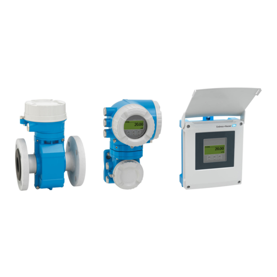
- Page 1 Products Solutions Services BA01725D/06/EN/03.19 71443177 2019-07-01 Valid as of version 01.01.zz (Device firmware) Operating Instructions Proline Promag W 500 PROFINET Electromagnetic flowmeter...
- Page 2 • The manufacturer reserves the right to modify technical data without prior notice. Your Endress+Hauser Sales Center will supply you with current information and updates to these instructions. Endress+Hauser...
-
Page 3: Table Of Contents
Setting the device name ... 71 Packaging disposal ..... 22 7.6.2 Activating the default IP address ..74 Endress+Hauser... - Page 4 System redundancy S2 ....113 totalizers" parameter ... . 166 11.7 Showing data logging ....Endress+Hauser...
- Page 5 13.2 Measuring and test equipment ... 215 13.3 Endress+Hauser services ....215 Repair ......216 14.1 General notes .
-
Page 6: About This Document
• Inner ground terminal: Connects the protectiv earth to the mains supply. • Outer ground terminal: Connects the device to the plant grounding system. 1.2.3 Communication symbols Symbol Meaning Wireless Local Area Network (WLAN) Communication via a wireless, local network. Light emitting diode is off. Endress+Hauser... -
Page 7: Tool Symbols
Result of a step. Help in the event of a problem. Visual inspection. 1.2.6 Symbols in graphics Symbol Meaning 1, 2, 3, ... Item numbers , … Series of steps A, B, C, ... Views A-A, B-B, C-C, ... Sections Hazardous area Endress+Hauser... -
Page 8: Documentation
• W@M Device Viewer (www.endress.com/deviceviewer): Enter the serial number from nameplate • Endress+Hauser Operations App: Enter the serial number from the nameplate or scan the 2D matrix code (QR code) on the nameplate Detailed list of the individual documents along with the documentation code →... -
Page 9: Safety Instructions
Danger of breakage due to corrosive or abrasive fluids and ambient conditions! ‣ Verify the compatibility of the process fluid with the sensor material. ‣ Ensure the resistance of all fluid-wetted materials in the process. ‣ Keep within the specified pressure and temperature range. Endress+Hauser... -
Page 10: Workplace Safety
Verification for borderline cases: ‣ For special fluids and fluids for cleaning, Endress+Hauser is glad to provide assistance in verifying the corrosion resistance of fluid-wetted materials, but does not accept any warranty or liability as minute changes in the temperature, concentration or level of contamination in the process can alter the corrosion resistance properties. -
Page 11: Security
Hardware write protection is disabled when the device is delivered → 156. 2.7.2 Protecting access via a password Different passwords are available to protect write access to the device parameters or access to the device via the WLAN interface. Endress+Hauser... -
Page 12: Access Via Web Server
(e.g. after commissioning) via the Web server functionality parameter. The device and status information can be hidden on the login page. This prevents unauthorized access to the information. For detailed information on device parameters, see: The "Description of Device Parameters" document → 254. Endress+Hauser... -
Page 13: Access Via Service Interface (Cdi-Rj45)
Order code for "Approval transmitter + sensor", options (Ex de): BA, BB, C1, C2, GA, GB, MA, MB, NA, NB The device can be integrated in a ring topology. The device is integrated via the terminal connection for signal transmission (output 1) and the connection to the service interface (CDI-RJ45) → 65. Endress+Hauser... -
Page 14: Product Description
• A standard cable can be used as the connecting cable. • Not sensitive to external EMC interference. A0029593 1 Important components of a measuring device Electronics compartment cover Display module Transmitter housing Sensor connection housing with integrated ISEM electronics: connecting cable connection Sensor Endress+Hauser... - Page 15 I/ O – A0029589 2 Important components of a measuring device Connection compartment cover Display module Transmitter housing with integrated ISEM electronics Electronics compartment cover Sensor Sensor connection housing: connecting cable connection Connection compartment cover: connecting cable connection Endress+Hauser...
-
Page 16: Incoming Acceptance And Product
Technical Documentation present? • If one of the conditions is not satisfied, contact your Endress+Hauser Sales Center. • Depending on the device version, the CD-ROM might not be part of the delivery! The Technical Documentation is available via the Internet or via the Endress+Hauser Operations App, see the "Product identification"... -
Page 17: Transmitter Nameplate
8 sections • The W@M Device Viewer: enter the serial number from the nameplate (www.endress.com/deviceviewer) • The Endress+Hauser Operations App: Enter the serial number from the nameplate or scan the 2-D matrix code (QR code) on the nameplate. 4.2.1 Transmitter nameplate Proline 500 –... - Page 18 Firmware version (FW) and device revision (Dev.Rev.) from the factory Space for additional information in the case of special products Permitted temperature range for cable Permitted ambient temperature (T Information on cable gland Available inputs and outputs, supply voltage Electrical connection data: supply voltage Endress+Hauser...
-
Page 19: Sensor Nameplate
(e.g. LA). If other optional specifications are also ordered, these are indicated collectively using the # placeholder symbol (e.g. #LA#). • If the ordered optional specifications do not include any safety and approval-related specifications, they are indicated by the + placeholder symbol (e.g. XXXXXX-ABCDE Endress+Hauser... -
Page 20: Symbols On Measuring Device
This symbol alerts you to a dangerous situation. Failure to avoid this situation can result in serious or fatal injury. Reference to documentation Refers to the corresponding device documentation. Protective ground connection A terminal which must be connected to ground prior to establishing any other connections. Endress+Hauser... -
Page 21: Storage And Transport
Center of gravity of the measuring device is higher than the suspension points of the webbing slings. Risk of injury if the measuring device slips. ‣ Secure the measuring device against slipping or turning. ‣ Observe the weight specified on the packaging (stick-on label). A0029214 Endress+Hauser... -
Page 22: Measuring Devices With Lifting Lugs
• Wooden crate treated in accordance with ISPM 15 standard, confirmed by IPPC logo • Cardboard box in accordance with European packaging guideline 94/62EC, recyclability confirmed by Resy symbol • Carrying and securing materials • Disposable plastic pallet • Plastic straps • Plastic adhesive strips • Filler material Paper pads Endress+Hauser... -
Page 23: Installation
≥ 5 m (16.4 ft). This precaution is to avoid low pressure and the consequent risk of damage to the measuring tube. This measure also prevents the system losing prime. A0028981 7 Installation in a down pipe Vent valve Pipe siphon Length of down pipe Endress+Hauser... - Page 24 To prevent the electronics module from overheating in the case of a sharp rise in temperature (e.g. CIP or SIP processes), install the device with the transmitter component pointing downwards. With the empty pipe detection function switched on: empty pipe detection only works if the transmitter housing is pointing upwards. Endress+Hauser...
- Page 25 For sensors with the order code for "Design", option C "Fixed flange, w/o inlet/outlet runs", no inlet and outlet runs must be taken into account. ≥ 0 × DN A0032859 Installation dimensions For the dimensions and installation lengths of the device, see the "Technical Information" document, "Mechanical construction" section. Endress+Hauser...
-
Page 26: Environment And Process Requirements
• Information on the vibration resistance of the measuring system → 236 Vibrations L > 10 m (33 ft) A0029004 8 Measures to prevent vibration of the device In the event of very strong vibrations, the pipe and sensor must be supported and fixed. Endress+Hauser... -
Page 27: Special Mounting Instructions
6 m/s 5 m/s 4 m/s 3 m/s max. 8° 2 m/s 1 m/s d / D A0029002 6.1.3 Special mounting instructions Protective cover 213 (8.4) 203 (8.0) A0029552 9 Weather protection cover for Proline 500 – digital Endress+Hauser... - Page 28 Im1/Im2/Im3 in accordance with EN ISO 12944. It can be used directly underground without the need for additional protective measures. The device is mounted in accordance with the usual regional installation regulations (e.g. EN DIN 1610). Endress+Hauser...
-
Page 29: Mounting The Measuring Device
2. To ensure compliance with device specifications, install the measuring device between the pipe flanges in a way that it is centered in the measurement section. 3. If using ground disks, comply with the Installation Instructions provided. 4. Observe required screw tightening torques → 30. Endress+Hauser... - Page 30 4 × M16 – 1 ½ PN 40 4 × M16 – PN 40 4 × M16 – PN 16 8 × M16 – PN 40 8 × M16 PN 16 8 × M16 PN 40 8 × M16 Endress+Hauser...
- Page 31 20 × M36 – PN 6 24 × M24 – PN 10 24 × M27 – PN 16 24 × M33 – PN 25 24 × M39 – PN 6 24 × M27 – PN 10 24 × M30 – Endress+Hauser...
- Page 32 [lbf · ft] Class 150 4 × ½ – – Class 300 4 × 5/8 – – 1 ½ Class 150 4 × ½ – – 1 ½ Class 300 4 × ¾ – – Class 150 4 × 5/8 Endress+Hauser...
- Page 33 4 × M16 8 × M16 8 × M16 8 × M20 8 × M16 8 × M20 8 × M20 8 × M22 8 × M20 12 × M22 12 × M20 12 × M22 12 × M22 Endress+Hauser...
- Page 34 8 × M20 – 12 × M20 – 12 × M24 – 12 × M24 – 12 × M24 – 16 × M24 – 16 × M24 – 16 × M30 – 20 × M30 – 20 × M30 – Endress+Hauser...
- Page 35 PN 10 28 × M33 – PN 16 28 × M39 – PN 25 28 × M52 1300 1290 – 1200 PN 6 32 × M30 – PN 10 32 × M36 – PN 16 32 × M45 – Endress+Hauser...
-
Page 36: Mounting The Transmitter Housing: Proline 500 - Digital
Ambient temperature too high! Danger of electronics overheating and housing deformation. ‣ Do not exceed the permitted maximum ambient temperature → 26. ‣ If operating outdoors: Avoid direct sunlight and exposure to weathering, particularly in warm climatic regions. Endress+Hauser... - Page 37 Excessive tightening torque applied to the fixing screws! Risk of damaging the plastic transmitter. ‣ Tighten the fixing screws as per the tightening torque: 2 Nm (1.5 lbf ft) ø 20…70 TX 25 ø ( 0.79…2.75) SW 10 A0029051 12 Engineering unit mm (in) Endress+Hauser...
-
Page 38: Mounting The Transmitter Housing: Proline 500
If operating outdoors: Avoid direct sunlight and exposure to weathering, particularly in warm climatic regions. CAUTION Excessive force can damage the housing! ‣ Avoid excessive mechanical stress. The transmitter can be mounted in the following ways: • Post mounting • Wall mounting Endress+Hauser... - Page 39 1. Drill the holes. 2. Insert wall plugs into the drilled holes. 3. Screw in the securing screws slightly at first. 4. Fit the transmitter housing over the securing screws and mount in place. 5. Tighten the securing screws. Endress+Hauser...
-
Page 40: Turning The Transmitter Housing: Proline 500
6. Screw on the connection compartment cover 7. Depending on the device version: Attach the securing clamp of the connection compartment cover. 6.2.7 Turning the display module: Proline 500 The display module can be turned to optimize display readability and operability. Endress+Hauser... -
Page 41: Post-Installation Check
Does the arrow on the sensor nameplate match the direction of flow of the fluid through the piping ? Are the measuring point identification and labeling correct (visual inspection)? Is the device adequately protected from precipitation and direct sunlight? Have the fixing screws been tightened with the correct tightening torque? Endress+Hauser... -
Page 42: Electrical Connection
PROFINET. CAT 5e and CAT 6 are recommended. For more information on planning and installing PROFINET networks, see: "PROFINET Cabling and Interconnection Technology", Guideline for PROFINET Current output 0/4 to 20 mA Standard installation cable is sufficient. Pulse/frequency/switch output Standard installation cable is sufficient. Endress+Hauser... - Page 43 Cable diameter • Cable glands supplied: M20 × 1.5 with cable ⌀ 6 to 12 mm (0.24 to 0.47 in) • Spring-loaded terminals: Suitable for strands and strands with ferrules. Conductor cross-section 0.2 to 2.5 mm (24 to 12 AWG). Endress+Hauser...
- Page 44 50 m (165 ft) 0.50 mm (AWG 20) 120 m (400 ft) 60 m (200 ft) 0.75 mm (AWG 18) 180 m (600 ft) 90 m (300 ft) 1.00 mm (AWG 17) 240 m (800 ft) 120 m (400 ft) Endress+Hauser...
- Page 45 5 m (15 ft), 10 m (32 ft), 20 m (65 ft) or variable length up to max. for order) 200 m (656 ft) Operating temperature –20 to +80 °C (–68 to +176 °F) Test voltage for cable ≤ AC 1433 V rms 50/60 Hz or ≥ DC 2026 V insulation Endress+Hauser...
-
Page 46: Terminal Assignment
The sensor and transmitter, which are mounted in separate locations, are interconnected by a connecting cable. The cable is connected via the sensor connection housing and the transmitter housing. Terminal assignment and connection of the connecting cable: • Proline 500 – digital→ 50 • Proline 500 → 58 Endress+Hauser... -
Page 47: Device Plugs Available
1. Remove dummy plug if present. 2. If the measuring device is supplied without cable glands: Provide suitable cable gland for corresponding connecting cable. 3. If the measuring device is supplied with cable glands: Observe requirements for connecting cables → 42. Endress+Hauser... -
Page 48: Preparing The Connecting Cable: Proline 500 - Digital
2. In the case of the coil current cable: Insulate one core of the three-core cable at the level of the core reinforcement. You only require two cores for the connection. 3. For cables with fine-wire cores (stranded cables): Fit the cores with ferrules. Endress+Hauser... - Page 49 A = Terminate the cable B = Fit ferrules on cables with fine-wire cores (stranded cables) 1 = Red ferrules, 1.0 mm (0.04 in) 2 = White ferrules, 0.5 mm (0.02 in) * = Stripping only for reinforced cables Endress+Hauser...
-
Page 50: Connecting The Measuring Device: Proline 500 - Digital
Connecting the connecting cable to the sensor connection housing Connection via terminals with order code for "Sensor connection housing": Option A "Aluminum, coated"→ 51 Connecting the connecting cable to the transmitter The cable is connected to the transmitter via terminals → 52. Endress+Hauser... - Page 51 Housing degree of protection voided due to insufficient sealing of the housing. ‣ Screw in the thread on the cover without using any lubricant. The thread on the cover is coated with a dry lubricant. 8. Screw on the housing cover. 9. Tighten the securing clamp of the housing cover. Endress+Hauser...
- Page 52 This concludes the process for connecting the connecting cable. 9. Close the housing cover. 10. Tighten the securing screw of the housing cover. 11. After connecting the connecting cable: Connect the signal cable and the supply voltage cable → 53. Endress+Hauser...
-
Page 53: Connecting The Transmitter
3. Fold open the terminal cover. 4. Push the cable through the cable entry . To ensure tight sealing, do not remove the sealing ring from the cable entry. 5. Strip the cable and cable ends and connect to the RJ45 connector. Endress+Hauser... - Page 54 Excessive tightening torque applied to the fixing screws! Risk of damaging the plastic transmitter. ‣ Tighten the fixing screws as per the tightening torque: 2 Nm (1.5 lbf ft) 8. Tighten the 4 fixing screws on the housing cover. Endress+Hauser...
- Page 55 A0029598 17 Engineering unit mm (in) 1. To remove a cable from the terminal, use a flat-blade screwdriver to push the slot between the two terminal holes 2. while simultaneously pulling the cable end out of the terminal. Endress+Hauser...
-
Page 56: Integrating The Transmitter Into A Network
Order code for "Accessories", option NB: "Adapter RJ45 M12 (service interface)" The adapter connects the service interface (CDI-RJ45) to an M12 connector mounted in the cable entry. Therefore the connection to the service interface can be established via an M12 connector without opening the device. Endress+Hauser... - Page 57 Order code for "Accessories", option NB: "Adapter RJ45 M12 (service interface)" The adapter connects the service interface (CDI-RJ45) to an M12 connector mounted in the cable entry. Therefore the connection to the service interface can be established via an M12 connector without opening the device. Endress+Hauser...
-
Page 58: Connecting The Measuring Device: Proline 500
Connection via terminals with order code for "Housing": • Option A "Aluminum coated"→ 59 • Option D "Polycarbonate"→ 59 Connecting the connecting cable to the transmitter The cable is connected to the transmitter via terminals → 60. Endress+Hauser... - Page 59 Housing degree of protection voided due to insufficient sealing of the housing. ‣ Screw in the thread on the cover without using any lubricant. The thread on the cover is coated with a dry lubricant. 8. Screw on the housing cover. 9. Tighten the securing clamp of the housing cover. Endress+Hauser...
- Page 60 This concludes the process for connecting the connecting cables. 8. Screw on the connection compartment cover. 9. Tighten the securing clamp of the connection compartment cover. 10. After connecting the connecting cables: Connect the signal cable and the supply voltage cable . Endress+Hauser...
-
Page 61: Connecting The Transmitter
ö ff I/ O N ic I/ O ri r iz e e rg s io te n I/ O – – A0029814 5. Attach the holder to the edge of the electronics compartment. 6. Open the terminal cover. Endress+Hauser... - Page 62 1. Push the cable through the cable entry . To ensure tight sealing, do not remove the sealing ring from the cable entry. 2. Strip the cable and cable ends. In the case of stranded cables, also fit ferrules. 3. Connect the protective ground. Endress+Hauser...
- Page 63 A0029598 18 Engineering unit mm (in) 1. To remove a cable from the terminal, use a flat-blade screwdriver to push the slot between the two terminal holes 2. while simultaneously pulling the cable end out of the terminal. Endress+Hauser...
-
Page 64: Integrating The Transmitter Into A Network
Order code for "Accessories", option NB: "Adapter RJ45 M12 (service interface)" The adapter connects the service interface (CDI-RJ45) to an M12 connector mounted in the cable entry. Therefore the connection to the service interface can be established via an M12 connector without opening the device. Endress+Hauser... -
Page 65: Ensuring Potential Equalization
M12 connector without opening the device. Ensuring potential equalization 7.4.1 Requirements CAUTION Electrode damage can result in the complete failure of the device! ‣ Same electrical potential for the fluid and sensor ‣ Company-internal grounding concepts ‣ Pipe material and grounding Endress+Hauser... -
Page 66: Connection Example, Standard Scenario
Plastic pipe or pipe with insulating liner This connection method also applies in situations where: • The customary potential equalization is not used • Equalizing currents are present Ground cable Copper wire, at least 6 mm (0.0093 in Endress+Hauser... - Page 67 1. Connect the two flanges of the pipe to one another via a ground cable. 2. Guide the shield of the signal lines through a capacitor. 3. Connect the measuring device to the power supply such that it is floating in relation to the protective ground (isolation transformer). Endress+Hauser...
-
Page 68: Special Connection Instructions
Connection example for PROFINET Control system (e.g. PLC) Ethernet switch Observe cable specifications Device plug Transmitter PROFINET: MRP (Media Redundancy Protocol) A0027544 Control system (e.g. PLC) Ethernet switch Observe cable specifications → 42 Transmitter Connecting cable between the two transmitters Endress+Hauser... - Page 69 Analog display unit: observe maximum load Transmitter 4...20 mA A0028759 25 Connection example for 4-20 mA current output (passive) Automation system with current input (e.g. PLC) Active barrier for power supply (e.g. RN221N) Analog display unit: observe maximum load Transmitter Endress+Hauser...
- Page 70 Automation system with switch input (e.g. PLC) Power supply Transmitter: Observe input values → 228 Relay output A0028760 28 Connection example for relay output (passive) Automation system with relay input (e.g. PLC) Power supply Transmitter: Observe input values → 229 Endress+Hauser...
-
Page 71: Hardware Settings
The tag name is equivalent to the device name (name of station of the PROFINET specification). The factory-assigned device name can be changed using the DIP switches or the automation system. Example of device name (factory setting): EH-Promag500-XXXX Endress+Hauser Promag Instrument family Transmitter... - Page 72 Setting the device name: Proline 500 - digital Risk of electric shock when opening the transmitter housing. ‣ Before opening the transmitter housing: ‣ Disconnect the device from the power supply. The default IP address may not be activated → 74. Endress+Hauser...
- Page 73 2. Depending on the housing version, unscrew or open the housing cover and disconnect the local display from the main electronics module where necessary . 3. Set the desired device name using the corresponding DIP switches on the I/O electronics module. 4. Reverse the removal procedure to reassemble the transmitter. Endress+Hauser...
-
Page 74: Activating The Default Ip Address
4. Set DIP switch No. 2 on the I/O electronics module from OFF → ON. 5. Reverse the removal procedure to reassemble the transmitter. 6. Reconnect the device to the power supply. The default IP address is used once the device is restarted. Endress+Hauser... -
Page 75: Ensuring The Degree Of Protection
4. Firmly tighten the cable glands. 5. To ensure that moisture does not enter the cable entry: Route the cable so that it loops down before the cable entry ("water trap"). A0029278 6. Insert dummy plugs into unused cable entries. Endress+Hauser... -
Page 76: Post-Connection Check
Do the cables used meet the requirements? Do the cables have adequate strain relief? Are all the cable glands installed, firmly tightened and leak-tight? Cable run with "water trap" → 75? Is the potential equalization established correctly ? Endress+Hauser... -
Page 77: Operation Options
Local operation via display module Computer with Web browser (e.g. Internet Explorer) or with operating tool (e.g. FieldCare, DeviceCare, AMS Device Manager, SIMATIC PDM) Field Xpert SFX350 or SFX370 Field Xpert SMT70 Mobile handheld terminal Control system (e.g. PLC) Endress+Hauser... -
Page 78: Structure And Function Of The Operating
Submenu 1 Submenu n Diagnostics Parameter 1 Parameter n Submenu 1 Submenu n Operating menu for experts Expert Access status display Parameter n System Sensor Input Output Communication Application Diagnostics A0018237-EN 31 Schematic structure of the operating menu Endress+Hauser... -
Page 79: Operating Philosophy
Configuration of the digital communication interface and the Web server. • Application Configuration of the functions that go beyond the actual measurement (e.g. totalizer). • Diagnostics Error detection and analysis of process and device errors and for device simulation and Heartbeat Technology. Endress+Hauser... -
Page 80: Access To The Operating Menu Via The Local Display
In the display area, each measured value is prefaced by certain symbol types for further description: Measured values Symbol Meaning Volume flow Conductivity Mass flow Totalizer The measurement channel number indicates which of the three totalizers is displayed. Status input Endress+Hauser... -
Page 81: Navigation View
• In the wizard: between • Wizard Display symbol for wizard • Parameters ↓ ↓ ↓ Examples / ../ Display / ../ Display For more information about the icons in the menu, refer to the "Display area" section → 82 Endress+Hauser... - Page 82 • By a user-specific access code • By the hardware write protection switch Wizard operation Symbol Meaning Switches to the previous parameter. Confirms the parameter value and switches to the next parameter. Opens the editing view of the parameter. Endress+Hauser...
-
Page 83: Editing View
Operating elements Move entry position Delete entry Reject or confirm entry Using the operating elements in the editing view Operating key(s) Meaning Minus key Move the entry position to the left. Plus key Move the entry position to the right. Endress+Hauser... - Page 84 Umlauts and accents Controlling data entries Symbol Meaning Move entry position Reject entry Confirm entry Delete character immediately to the left of the entry position Delete character immediately to the right of the entry position Clear all the characters entered Endress+Hauser...
-
Page 85: Operating Elements
Press the key for 3 s: the context menu opens along with the option for activating the keypad lock. 8.3.5 Opening the context menu Using the context menu, the user can call up the following menus quickly and directly from the operational display: • Setup • Data backup • Simulation Endress+Hauser... - Page 86 The context menu is closed and the operational display appears. Calling up the menu via the context menu 1. Open the context menu. 2. Press to navigate to the desired menu. 3. Press to confirm the selection. The selected menu opens. Endress+Hauser...
-
Page 87: Navigating And Selecting From List
A parameter number is assigned to every parameter to be able to access a parameter directly via the onsite display. Entering this access code in the Direct access parameter calls up the desired parameter directly. Navigation path Expert → Direct access Endress+Hauser... -
Page 88: Calling Up Help Text
Parameters can be changed via the numeric editor or text editor. • Numeric editor: Change values in a parameter, e.g. specifications for limit values. • Text editor: Enter text in a parameter, e.g. tag name. A message is displayed if the value entered is outside the permitted value range. Endress+Hauser... -
Page 89: User Roles And Related Access Authorization
Parameter write protection via local operation can be disabled by entering the user-specific access code in the Enter access code parameter (→ 140) via the respective access option. 1. After you press , the input prompt for the access code appears. Endress+Hauser... -
Page 90: Enabling And Disabling The Keypad
WLAN connection: order code for "Display; operation", option G "4-line, illuminated; touch control + WLAN". The device acts as an Access Point and enables communication by computer or a mobile handheld terminal. For additional information on the Web server, refer to the Special Documentation for the device Endress+Hauser... -
Page 91: Prerequisites
Network connections Only the active network connections to the measuring device should be used. Switch off all other network Switch off all other network connections such as WLAN. connections. In the event of connection problems: → 171 Endress+Hauser... -
Page 92: Establishing A Connection
The IP address is entered via the IP address parameter (→ 118) . • DIP switch for "Default IP address": To establish the network connection via the service interface (CDI-RJ45): the fixed IP address 192.168.1.212 is used → 74. Endress+Hauser... - Page 93 Enable WLAN reception on the mobile terminal. Establishing a connection from the mobile terminal to the measuring device 1. In the WLAN settings of the mobile terminal: Select the measuring device using the SSID (e.g. EH_Promag_500_A802000). 2. If necessary, select the WPA2 encryption method. Endress+Hauser...
-
Page 94: Logging On
User role Access code Login Reset access code (→ 152) If a login page does not appear, or if the page is incomplete → 171 8.4.4 Logging on 1. Select the preferred operating language for the Web browser. Endress+Hauser... -
Page 95: User Interface
(PDF file, only available with the "Heartbeat Verification" application package) • File for system integration - If using fieldbuses, upload device drivers for system integration from the measuring device: PROFINET: GSD file • Firmware update - Flashing a firmware version Endress+Hauser... -
Page 96: Disabling The Web Server
Enabling the Web server If the Web server is disabled it can only be re-enabled with the Web server functionality parameter via the following operating options: • Via local display • Via Bedientool "FieldCare" • Via "DeviceCare" operating tool Endress+Hauser... -
Page 97: Logging Out
(e.g. FieldCare, DeviceCare, SIMATIC PDM) with COM DTM "CDI Communication TCP/IP" Switch, e.g. Scalance X204 (Siemens) Measuring device Ring topology The device is integrated via the terminal connection for signal transmission (output 1) and the service interface (CDI-RJ45). Endress+Hauser... - Page 98 Computer with Web browser (e.g. Microsoft Internet Explorer, Microsoft Edge) for accessing the integrated device Web server or with "FieldCare", "DeviceCare" operating tool with COM DTM "CDI Communication TCP/IP" Standard Ethernet connecting cable with RJ45 connector Service interface (CDI-RJ45) of the measuring device with access to the integrated Web server Endress+Hauser...
- Page 99 Web server or with operating tool (e.g. FieldCare, DeviceCare) Mobile handheld terminal with WLAN interface and Web browser (e.g. Microsoft Internet Explorer, Microsoft Edge) for accessing the integrated device Web server or operating tool (e.g. FieldCare, DeviceCare) Smart phone or tablet (e.g. Field Xpert SMT70) Endress+Hauser...
- Page 100 SSID name. It should be possible to clearly assign the new SSID name to the measuring point (e.g. tag name) because it is displayed as the WLAN network. Disconnecting ‣ After configuring the device: Terminate the WLAN connection between the operating unit and measuring device. Endress+Hauser...
-
Page 101: Fieldcare
FieldCare Function scope FDT-based plant asset management tool from Endress+Hauser. It can configure all smart field devices in a system and helps you manage them. By using the status information, it is also a simple but effective way of checking their status and condition. -
Page 102: Devicecare
DeviceCare Function scope Tool to connect and configure Endress+Hauser field devices. The fastest way to configure Endress+Hauser field devices is with the dedicated "DeviceCare" tool. Together with the device type managers (DTMs) it presents a convenient, comprehensive solution. For details, see Innovation Brochure IN01047S Source for device description files See information →... -
Page 103: System Integration
Operating tool via Sources for obtaining device descriptions Service interface (CDI) FieldCare • www.endress.com → Download Area • CD–ROM (contact Endress+Hauser) • DVD (contact Endress+Hauser) DeviceCare • www.endress.com → Download Area • CD–ROM (contact Endress+Hauser) • DVD (contact Endress+Hauser) -
Page 104: File Name Of The Device Master File (Gsd)
File name of the device master file (GSD) Example of the name of a device master file: GSDML-V2.3.x-EH-PROMAG 500-yyyymmdd.xml GSDML Description language V2.3.x Version of the PROFINET specification Endress+Hauser PROMAG Instrument family Transmitter yyyymmdd Date of issue (yyyy: year, mm: month, dd: day) .xml... -
Page 105: Cyclic Data Transmission
• Mass flow • Corrected volume flow • Flow velocity • Conductivity 1…10 • Corrected conductivity • Temperature • Electronics temperature • Noise • Coil current rise time • Reference electrode potential against PE 18 to 20 Current input value Endress+Hauser... - Page 106 (→ 185). The third byte provides the status. Selection: device function Slot Device function Status (meaning) Last diagnostics Diagnostic information number 1…10 (→ 185) and status Current diagnosis Information about pending diagnostic information → 209. Endress+Hauser...
- Page 107 Data structure of input data (Totalizer Value submodule) Byte 1 Byte 2 Byte 3 Byte 4 Byte 5 Measured value: floating point number (IEEE 754) Status Status coding → 111 Totalizer Control submodule Control the totalizer via the automation system. Endress+Hauser...
- Page 108 IEEE 754 standard. The fifth byte contains standardized status information pertaining to the compensation value. The unit is transmitted in the sixth and seventh byte. Assigned compensation values The configuration is performed via: Expert → Sensor → External compensation Slot Compensation value External density External temperature Endress+Hauser...
- Page 109 • Fallback value option: The last valid value is used. • Off option: The failsafe mode is disabled. Fail safe value parameter Use this parameter to enter the compensation value which is used if the Fail safe value option is selected in the Fail safe type parameter. Endress+Hauser...
- Page 110 Only available with the Heartbeat Verification application package. Assigned device functions Slot Device function Verification status Verification has not been performed Verification has failed Status verification (input data) Currently performing verification Verification terminated Verification result Verification result Endress+Hauser...
-
Page 111: Status Coding
It is highly advisable to service the device in the near future. GOOD - Function check 0xBC The measured value is valid. The measuring device is performing an internal function check. The function check does not have any noticeable effect on the process. Endress+Hauser... -
Page 112: Factory Setting
• Pressure shock suppression • Empty pipe detection: • Assign process variable • Limit values • Response time • External compensation: • Temperature source • Density source • Density value • Diagnostic settings • Diagnostic behavior for diverse diagnostic information Endress+Hauser... -
Page 113: System Redundancy S2
40 Example of the layout of a redundant system (S2): star topology Automation system 1 Synchronization of automation systems Automation system 2 Industrial Ethernet Managed Switch Measuring device All the devices in the network must support S2 system redundancy. Endress+Hauser... -
Page 114: Commissioning
Main menu 0104-1 Display language English Operation Setup Display language 0104-1 English à Deutsch Español Français Display language 0104-1 à English Deutsch Español Français Hauptmenü 0104-1 Sprache Deutsch Betrieb Setup A0029420 41 Taking the example of the local display Endress+Hauser... -
Page 115: Configuring The Measuring Device
→ 119 ‣ Current input 1 to n → 120 ‣ Status input 1 to n → 121 ‣ Current output 1 to n → 122 ‣ Pulse/frequency/switch output → 125 1 to n Endress+Hauser... -
Page 116: Defining The Tag Name
(→ "Supplementary documentation" section). Navigation "Setup" menu → System units ‣ System units Volume flow unit → 117 Volume unit → 117 Conductivity unit → 117 Temperature unit → 117 Mass flow unit → 117 Endress+Hauser... - Page 117 Mass unit – Select mass unit. Unit choose list Country-specific: • kg • lb Density unit – Select density unit. Unit choose list Country-specific: • kg/l Result • lb/ft³ The selected unit applies for: • Output • Simulation process variable Endress+Hauser...
-
Page 118: Displaying The Communication
Subnet mask can also be entered. Default gateway Displays the default gateway. 4 octet: 0 to 255 (in the 0.0.0.0 particular octet) If the DHCP client is switched off and write access is enabled, the Default gateway can also be entered. Endress+Hauser... -
Page 119: Selecting And Setting The Medium
I/O modules is displayed. Navigation "Setup" menu → I/O configuration ‣ I/O configuration I/O module 1 to n terminal numbers → 120 I/O module 1 to n information → 120 I/O module 1 to n type → 120 Endress+Hauser... -
Page 120: Configuring The Current Input
Navigation "Setup" menu → Current input ‣ Current input 1 to n Terminal number → 121 Signal mode → 121 0/4 mA value → 121 → 121 20 mA value Current span → 121 Endress+Hauser... -
Page 121: Configuring The Status Input
The Status input submenu guides the user systematically through all the parameters that have to be set for configuring the status input. Navigation "Setup" menu → Status input ‣ Status input 1 to n Assign status input → 122 Terminal number → 122 → 122 Active level Endress+Hauser... -
Page 122: Configuring The Current Output
Assign current output 1 to n → 123 Current span → 123 0/4 mA value → 123 20 mA value → 123 Fixed current → 124 → 124 Damping output 1 to n Endress+Hauser... - Page 123 Depends on country selected in the Current span number and nominal parameter (→ 123): diameter • 4...20 mA NAMUR (3.8...20.5 mA) • 4...20 mA US (3.9...20.8 • 4...20 mA (4... 20.5 mA) • 0...20 mA (0... 20.5 mA) Endress+Hauser...
- Page 124 • 0...20 mA (0... 20.5 mA) Failure current The Defined value option is Enter current output value in 0 to 22.5 mA 22.5 mA selected in the Failure mode alarm condition. parameter. Visibility depends on order options or device settings Endress+Hauser...
-
Page 125: Configuring The Pulse/Frequency
→ 126 Terminal number → 126 Signal mode → 126 Assign pulse output → 126 Value per pulse → 126 Pulse width → 126 → 126 Failure mode Invert output signal → 126 Endress+Hauser... - Page 126 • Yes Configuring the frequency output Navigation "Setup" menu → Pulse/frequency/switch output ‣ Pulse/frequency/switch output 1 to n → 127 Operating mode Terminal number → 127 Signal mode → 127 Assign frequency output → 127 Endress+Hauser...
- Page 127 Minimum frequency value The Frequency option is Enter minimum frequency. 0.0 to 10 000.0 Hz 0.0 Hz selected in the Operating mode parameter (→ 125) and a process variable is selected in the Assign frequency output parameter (→ 127). Endress+Hauser...
- Page 128 (→ 125) and a process variable is selected in the Assign frequency output parameter (→ 127). Invert output signal – Invert the output signal. • No • Yes Visibility depends on order options or device settings Endress+Hauser...
- Page 129 • Not used – used by the PFS output • 24-25 (I/O 2) module. • 22-23 (I/O 3) • 20-21 (I/O 4) Signal mode – Select the signal mode for the • Passive Passive PFS output. • Active • Passive NAMUR Endress+Hauser...
- Page 130 Switch-on delay • The Switch option is Define delay for the switch-on 0.0 to 100.0 s 0.0 s selected in the Operating of status output. mode parameter. • The Limit option is selected in the Switch output function parameter. Endress+Hauser...
-
Page 131: 10.5.10 Configuring The Relay Output
→ 132 Assign flow direction check → 132 Assign limit → 132 Assign diagnostic behavior → 132 Assign status → 132 Switch-off value → 132 → 132 Switch-on value Failure mode → 132 Endress+Hauser... - Page 132 0.0 to 100.0 s 0.0 s parameter, the Limit option is of status output. selected. Failure mode – Define output behavior in • Actual status Open alarm condition. • Open • Closed Visibility depends on order options or device settings Endress+Hauser...
-
Page 133: 10.5.11 Configuring The Local Display
100% bargraph value 1 → 134 Value 2 display → 135 Value 3 display → 135 0% bargraph value 3 → 135 100% bargraph value 3 → 136 Value 4 display → 136 Endress+Hauser... - Page 134 Enter 0% value for bar graph Signed floating-point Country-specific: display. number • 0 l/h • 0 gal/min (us) 100% bargraph value 1 A local display is provided. Enter 100% value for bar Signed floating-point Depends on country graph display. number and nominal diameter Endress+Hauser...
- Page 135 • Test point 2 • Test point 3 0% bargraph value 3 A selection was made in the Enter 0% value for bar graph Signed floating-point Country-specific: Value 3 display parameter. display. number • 0 l/h • 0 gal/min (us) Endress+Hauser...
-
Page 136: 10.5.12 Configuring The Low Flow Cut Off
"Setup" menu → Low flow cut off ‣ Low flow cut off Assign process variable → 137 On value low flow cutoff → 137 Off value low flow cutoff → 137 Pressure shock suppression → 137 Endress+Hauser... - Page 137 Assign process variable off. parameter (→ 137). Pressure shock suppression A process variable is selected Enter time frame for signal 0 to 100 s in the Assign process variable suppression (= active pressure parameter (→ 137). shock suppression). Endress+Hauser...
-
Page 138: 10.5.13 Configuring Empty Pipe Detection
Response time empty pipe detection A process variable is selected Enter the time before 0 to 100 s in the Assign process variable diagnostic message S862 ' ' P ipe parameter (→ 138). empty' ' is displayed for empty pipe detection. Endress+Hauser... -
Page 139: Advanced Settings
"Setup" menu → Advanced setup ‣ Advanced setup Enter access code → 140 ‣ Sensor adjustment → 140 ‣ Totalizer 1 to n → 140 ‣ → 142 Display ‣ Electrode cleaning circuit → 146 Endress+Hauser... -
Page 140: Using The Parameter To Enter The Access Code
10.6.3 Configuring the totalizer In the "Totalizer 1 to n" submenu the individual totalizer can be configured. Navigation "Setup" menu → Advanced setup → Totalizer 1 to n ‣ Totalizer 1 to n → 141 Assign process variable Endress+Hauser... - Page 141 Net flow total • Forward flow total • Reverse flow total • Last valid value Failure mode Define the totalizer behavior in the event of • Stop Actual value a device alarm. • Actual value • Last valid value Endress+Hauser...
-
Page 142: Carrying Out Additional Display Configurations
→ 145 Decimal places 4 → 145 Display language → 146 Display interval → 146 Display damping → 146 → 146 Header → 146 Header text Separator → 146 Backlight → 146 Endress+Hauser... - Page 143 Decimal places 1 A measured value is specified Select the number of decimal • x x.xx in the Value 1 display places for the display value. • x.x parameter. • x.xx • x.xxx • x.xxxx Endress+Hauser...
- Page 144 • Current output 3 • Current output 4 • Temperature • Electronic temperature • Noise • Coil current shot time • Reference electrode potential against PE • Coating measured value • Test point 1 • Test point 2 • Test point 3 Endress+Hauser...
- Page 145 • Test point 3 Decimal places 4 A measured value is specified Select the number of decimal • x x.xx in the Value 4 display places for the display value. • x.x parameter. • x.xx • x.xxx • x.xxxx Endress+Hauser...
-
Page 146: Performing Electrode Cleaning
Visibility depends on order options or device settings 10.6.5 Performing electrode cleaning The Electrode cleaning circuit submenu contains parameters that must be configured for the configuration of electrode cleaning. The submenu is only available if the device was ordered with electrode cleaning. Endress+Hauser... -
Page 147: Wlan Configuration
WLAN configuration The WLAN Settings submenu guides the user systematically through all the parameters that have to be set for the WLAN configuration. Navigation "Setup" menu → Advanced setup → WLAN settings ‣ WLAN settings WLAN → 148 Endress+Hauser... - Page 148 • EAP-TLS Security identification – Select security settings and • Trusted issuer – download these settings via certificate menu Data management > • Device certificate Security > WLAN. • Device private key User name – Enter user name. – – Endress+Hauser...
-
Page 149: Configuration Management
Configuration backup submenu. Navigation "Setup" menu → Advanced setup → Configuration backup ‣ Configuration backup Operating time → 150 Last backup → 150 → 150 Configuration management → 150 Backup state Comparison result → 150 Endress+Hauser... -
Page 150: Using Parameters For Device Administration
While this action is in progress, the configuration cannot be edited via the local display and a message on the processing status appears on the display. 10.6.8 Using parameters for device administration The Administration submenu systematically guides the user through all the parameters that can be used for device administration purposes. Endress+Hauser... - Page 151 Using the parameter to reset the access code Navigation "Setup" menu → Advanced setup → Administration → Reset access code ‣ Reset access code → 152 Operating time → 152 Reset access code Endress+Hauser...
-
Page 152: Simulation
Character string comprising 0x00 numbers, letters and special For a reset code, contact your characters Endress+Hauser service organization. The reset code can only be entered via: • Web browser • DeviceCare, FieldCare (via service interface CDI-RJ45) • Fieldbus Using the parameter to reset the device Navigation "Setup"... - Page 153 • On Value current input 1 to n In the Current input 1 to n Enter the current value for 0 to 22.5 mA 0 mA simulation parameter, the On simulation. option is selected. Endress+Hauser...
- Page 154 Down-counting value option is selected. Device alarm simulation – Switch the device alarm on and • Off off. • On Diagnostic event category – Select a diagnostic event • Sensor Process category. • Electronics • Configuration • Process Endress+Hauser...
-
Page 155: Protecting Settings From Unauthorized
→ 89. • The user role with which the user is currently logged on via the local display → 89 is indicated by the Access status parameter. Navigation path: Operation → Access status Endress+Hauser... -
Page 156: Write Protection Via Write Protection
Via Web browser, FieldCare, DeviceCare (via CDI-RJ45 service interface), fieldbus For a reset code, contact your Endress+Hauser service organization. 1. Navigate to the Reset access code parameter (→ 152). 2. Enter the reset code. - Page 157 (factory setting) disables hardware write protection. No option is displayed in the Locking status parameter → 159. On the local display, the -symbol disappears from in front of the parameters in the header of the operational display and in the navigation view. Endress+Hauser...
- Page 158 (factory setting) disables hardware write protection. No option is displayed in the Locking status parameter → 159. On the local display, the -symbol disappears from in front of the parameters in the header of the operational display and in the navigation view. Endress+Hauser...
-
Page 159: Operation
With the Measured values submenu, it is possible to read all the measured values. Navigation "Diagnostics" menu → Measured values ‣ Measured values ‣ Process variables → 160 ‣ → 161 Input values ‣ Output values → 163 ‣ Totalizer → 160 Endress+Hauser... -
Page 160: Process Variables" Submenu
Displays the current fixed density or density read in from an Signed floating-point number external device. Dependency The unit is taken from the Density unit parameter. 11.4.2 Totalizer The Totalizer submenu contains all the parameters needed to display the current measured values for every totalizer. Endress+Hauser... -
Page 161: Input Values" Submenu
Totalizer status (Hex) 1 to n In Target mode parameter, Displays the current status 0 to 0xFF – the Auto option is selected. value (hex) of the totalizer. 11.4.3 "Input values" submenu The Input values submenu guides you systematically to the individual input values. Endress+Hauser... - Page 162 "Diagnostics" menu → Measured values → Input values → Status input 1 to n ‣ Status input 1 to n Value status input → 162 Parameter overview with brief description Parameter Description User interface Value status input Shows the current input signal level. • High • Low Endress+Hauser...
-
Page 163: Output Values
Displays the current value currently measured for the current 0 to 30 mA output. Output values for pulse/frequency/switch output The Pulse/frequency/switch output 1 to n submenu contains all the parameters needed to display the current measured values for every pulse/frequency/switch output. Endress+Hauser... - Page 164 User interface Switch status Shows the current relay switch status. • Open • Closed Switch cycles Shows number of all performed switch cycles. Positive integer Max. switch cycles number Shows the maximal number of guaranteed switch cycles. Positive integer Endress+Hauser...
-
Page 165: Adapting The Measuring Device To The Process
The totaling process is stopped and the totalizer is reset to 0. Preset + hold The totaling process is stopped and the totalizer is set to its defined start value from the Preset value parameter. Reset + totalize The totalizer is reset to 0 and the totaling process is restarted. Endress+Hauser... -
Page 166: Function Scope Of The "Reset All Totalizers" Parameter
If the length of the logging interval or the assignment of the process variables to the channels is changed, the content of the data logging is deleted. Navigation "Diagnostics" menu → Data logging ‣ Data logging Assign channel 1 → 168 Assign channel 2 → 168 Assign channel 3 → 168 Endress+Hauser... - Page 167 Logging delay → 169 Data logging control → 169 Data logging status → 169 → 169 Entire logging duration ‣ Display channel 1 ‣ Display channel 2 ‣ Display channel 3 ‣ Display channel 4 Endress+Hauser...
- Page 168 Clear logging data The Extended HistoROM Clear the entire logging data. • Cancel Cancel application package is • Clear data available. Data logging – Select the data logging • Overwriting Overwriting method. • Not overwriting Endress+Hauser...
- Page 169 • Active • Stopped Entire logging duration In the Data logging Displays the total logging Positive floating- parameter, the Not duration. point number overwriting option is selected. Visibility depends on order options or device settings Endress+Hauser...
-
Page 170: Diagnostics And Troubleshooting
Message on local display: Communication between the • Check the cable and the "Communication Error" display module and the electronics connector between the main "Check Electronics" is interrupted. electronics module and display module. • Order spare part → 216. Endress+Hauser... - Page 171 Using the example of MS Internet Explorer: 1. Under Control Panel open Internet options. 2. Select the Connections tab and then double-click LAN settings. 3. In the LAN settings disable the use of the proxy server and select OK to confirm. Endress+Hauser...
- Page 172 Depending on the settings of the or DeviceCare via CDI-RJ45 service preventing communication firewall used on the computer or in interface (via port 8000 or TFTP the network, the firewall must be ports) adapted or disabled to allow FieldCare/DeviceCare access. Endress+Hauser...
-
Page 173: Diagnostic Information Via Light Emitting
3. Fold open the terminal cover. Color Meaning Supply voltage Supply voltage is off or too low. Green Supply voltage is ok. Device status (normal Firmware error operation) Green Device status is ok. Flashing green Device is not configured. Endress+Hauser... - Page 174 Port 1 active: PROFINET Port 2 active: PROFINET and service interface (CDI) Color Meaning Supply voltage Supply voltage is off or too low. Green Supply voltage is ok. Device status (normal Firmware error. operation) Green Device status is ok. Endress+Hauser...
-
Page 175: Sensor Connection Housing
Proline 500 – digital Various light emitting diodes (LED) on the ISEM electronics (Intelligent Sensor Electronic Module) in the sensor connection housing provide information on the device status. Communication Communication Alarm Power Power A0029699 Communication Device status Supply voltage Endress+Hauser... - Page 176 Flashes red slowly If > 30 seconds: problem with the boot loader. start-up) Flashes red quickly If > 30 seconds: compatibility problem when reading the firmware. Supply voltage Green Supply voltage is ok. Supply voltage is off or too low. Endress+Hauser...
-
Page 177: Diagnostic Information On Local Display
Function check The device is in service mode (e.g. during a simulation). Out of specification The device is operated: Outside its technical specification limits (e.g. outside the process temperature range) Maintenance required Maintenance is required. The measured value remains valid. Endress+Hauser... - Page 178 Operating elements Meaning Plus key In a menu, submenu Opens the message about remedy information. Enter key In a menu, submenu Opens the operating menu. Endress+Hauser...
-
Page 179: Calling Up Remedial Measures
The message for the remedial measures closes. 12.4 Diagnostic information in the Web browser 12.4.1 Diagnostic options Any faults detected by the measuring device are displayed in the Web browser on the home page once the user has logged on. Endress+Hauser... -
Page 180: Calling Up Remedy Information
These measures are displayed in red along with the diagnostic event and the related diagnostic information. 12.5 Diagnostic information in FieldCare or DeviceCare 12.5.1 Diagnostic options Any faults detected by the measuring device are displayed on the home page of the operating tool once the connection has been established. Endress+Hauser... -
Page 181: Calling Up Remedy Information
Remedy information can be called up in the working area of the user interface. The user is in the Diagnostics menu. 1. Call up the desired parameter. 2. On the right in the working area, mouse over the parameter. A tool tip with remedy information for the diagnostic event appears. Endress+Hauser... -
Page 182: Adapting The Diagnostic Information
Depending on which failsafe mode has been configured, status information in accordance with PROFIBUS PA Profile Specification 3.02 is transmitted to the the PROFINET controller via the status byte. The two bits for the limits always have the value Endress+Hauser... - Page 183 Diagnostic information pertaining to the electronics: diagnostic number 200 to 399 Diagnostic number 200 to 301, 303 to 399 Measured value status (fixed assignment) Diagnostic behavior Device diagnosis Quality Coding Category (configurable) (fixed assignment) Quality Substatus (hex) (NE107) Alarm Maintenance Maintenance 0x24 alarm (Failure) alarm Warning Endress+Hauser...
- Page 184 Diagnostic behavior Device diagnosis Quality Coding Category (configurable) (fixed assignment) Quality Substatus (hex) (NE107) Process Invalid process Alarm 0x28 related (Failure) condition UNCERTA Process Invalid process Warning 0x78 (Out of related condition specification) Logbook entry only GOOD 0x80 – – Endress+Hauser...
-
Page 185: Overview Of Diagnostic Information
0x24 to 0x27 • Flow velocity • Mass flow Status signal • Coil current shot time Diagnostic behavior Alarm • Reference electrode potential against PE • Noise • Reference density • Corrected volume flow • Temperature • Status • Volume flow Endress+Hauser... - Page 186 • Mass flow Quality substatus • Coil current shot time • Reference electrode Coding (hex) 0x80 to 0x83 potential against PE • Noise Status signal • Corrected volume flow Diagnostic behavior Warning • Temperature • Status • Volume flow Endress+Hauser...
- Page 187 • Mass flow • Coil current shot time Coding (hex) 0x24 to 0x27 • Reference electrode potential against PE Status signal • Noise Diagnostic behavior Alarm • Reference density • Corrected volume flow • Temperature • Status • Volume flow Endress+Hauser...
-
Page 188: Diagnostic Of Electronic
0x80 to 0x83 • Flow velocity • Mass flow Status signal • Coil current shot time Diagnostic behavior Alarm • Reference electrode potential against PE • Noise • Reference density • Corrected volume flow • Temperature • Volume flow Endress+Hauser... - Page 189 0x24 to 0x27 • Flow velocity • Mass flow Status signal • Coil current shot time Diagnostic behavior Alarm • Reference electrode potential against PE • Noise • Reference density • Corrected volume flow • Temperature • Status • Volume flow Endress+Hauser...
- Page 190 0x24 to 0x27 • Flow velocity • Mass flow Status signal • Coil current shot time Diagnostic behavior Alarm • Reference electrode potential against PE • Noise • Reference density • Corrected volume flow • Temperature • Status • Volume flow Endress+Hauser...
- Page 191 0x24 to 0x27 • Flow velocity • Mass flow Status signal • Coil current shot time Diagnostic behavior Alarm • Reference electrode potential against PE • Noise • Reference density • Corrected volume flow • Temperature • Status • Volume flow Endress+Hauser...
- Page 192 0x24 to 0x27 • Flow velocity • Mass flow Status signal • Coil current shot time Diagnostic behavior Warning • Reference electrode potential against PE • Noise • Reference density • Corrected volume flow • Temperature • Status • Volume flow Endress+Hauser...
- Page 193 0x24 to 0x27 • Flow velocity • Mass flow Status signal • Coil current shot time Diagnostic behavior Alarm • Reference electrode potential against PE • Noise • Reference density • Corrected volume flow • Temperature • Status • Volume flow Endress+Hauser...
- Page 194 0x24 to 0x27 • Flow velocity • Mass flow Status signal • Coil current shot time Diagnostic behavior Alarm • Reference electrode potential against PE • Noise • Reference density • Corrected volume flow • Temperature • Status • Volume flow Endress+Hauser...
- Page 195 Diagnostic behavior can be changed. This causes the overall status of the measured variable to change. Diagnostic information Remedy instructions Influenced measured variables Short text 378 Supply voltage ISEM faulty Check supply voltage to the ISEM – Measured variable status Quality Good Quality substatus Coding (hex) 0x80 to 0x83 Status signal Diagnostic behavior Alarm Endress+Hauser...
- Page 196 Quality substatus Maintenance alarm • Density • Electronic temperature Coding (hex) 0x24 to 0x27 • Flow velocity • Mass flow Status signal • Reference density Diagnostic behavior Alarm • Corrected volume flow • Temperature • Status • Volume flow Endress+Hauser...
-
Page 197: Diagnostic Of Configuration
0x24 to 0x27 • Flow velocity • Mass flow Status signal • Coil current shot time Diagnostic behavior Warning • Reference electrode potential against PE • Noise • Reference density • Corrected volume flow • Temperature • Volume flow Endress+Hauser... - Page 198 • Status • Volume flow Diagnostic information Remedy instructions Influenced measured variables Short text 431 Trim 1 to n Carry out trim – Measured variable status Quality Good Quality substatus Coding (hex) 0x80 to 0x83 Status signal Diagnostic behavior Warning Endress+Hauser...
- Page 199 2. Check current output settings Measured variable status [from the factory] Quality Good Quality substatus Coding (hex) 0x80 to 0x83 Status signal Diagnostic behavior Warning Diagnostic behavior can be changed. This causes the overall status of the measured variable to change. Endress+Hauser...
- Page 200 Measured variable status [from the factory] • Measured values 3 Quality Good Quality substatus Coding (hex) 0x80 to 0x83 Status signal Diagnostic behavior Warning Diagnostic behavior can be changed. This causes the overall status of the measured variable to change. Endress+Hauser...
- Page 201 • Mass flow • Coil current shot time Coding (hex) 0xBC to 0xBF • Reference electrode potential against PE Status signal • Noise Diagnostic behavior Warning • Reference density • Corrected volume flow • Temperature • Status • Volume flow Endress+Hauser...
- Page 202 Warning Diagnostic information Remedy instructions Influenced measured variables Short text 493 Simulation pulse output 1 to n Deactivate simulation pulse output – Measured variable status Quality Good Quality substatus Coding (hex) 0x80 to 0x83 Status signal Diagnostic behavior Warning Endress+Hauser...
- Page 203 • Mass flow • Coil current shot time Coding (hex) 0x24 to 0x27 • Reference electrode potential against PE Status signal • Noise Diagnostic behavior Alarm • Reference density • Corrected volume flow • Temperature • Status • Volume flow Endress+Hauser...
- Page 204 Diagnostic information Remedy instructions Influenced measured variables Short text 537 Configuration 1. Check IP addresses in network – 2. Change IP address Measured variable status Quality Good Quality substatus Coding (hex) 0x80 to 0x83 Status signal Diagnostic behavior Warning Endress+Hauser...
-
Page 205: Diagnostic Of Process
Warning • Reference electrode potential against PE • Noise • Reference density • Corrected volume flow • Temperature • Status • Volume flow Diagnostic behavior can be changed. This causes the overall status of the measured variable to change. Endress+Hauser... - Page 206 0x80 to 0x83 potential against PE • Noise Status signal • Corrected volume flow Diagnostic behavior Warning • Temperature • Status • Volume flow Diagnostic behavior can be changed. This causes the overall status of the measured variable to change. Endress+Hauser...
- Page 207 PE Status signal • Noise Diagnostic behavior Warning • Reference density • Corrected volume flow • Temperature • Status • Volume flow Diagnostic behavior can be changed. This causes the overall status of the measured variable to change. Endress+Hauser...
- Page 208 PE Coding (hex) 0x80 to 0x83 • Noise • Corrected volume flow Status signal • Status Diagnostic behavior Warning • Volume flow Diagnostic behavior can be changed. This causes the overall status of the measured variable to change. Endress+Hauser...
-
Page 209: Pending Diagnostic Events
Up to 5 currently pending diagnostic events can be displayed in the Diagnostic list submenu along with the associated diagnostic information. If more than 5 diagnostic events are pending, the events with the highest priority are shown on the display. Navigation path Diagnostics → Diagnostic list Endress+Hauser... -
Page 210: 12.10 Event Logbook
• Via local display → 179 • Via Web browser → 180 • Via "FieldCare" operating tool → 181 • Via "DeviceCare" operating tool → 181 For filtering the displayed event messages → 211 Endress+Hauser... -
Page 211: 12.10.2 Filtering The Event Logbook
I1443 Coating thickness not determined I1444 Device verification passed I1445 Device verification failed I1457 Measurement error verification failed I1459 I/O module verification failed I1461 Sensor verification failed I1462 Sensor electronic module verific. failed I1512 Download started I1513 Download finished Endress+Hauser... -
Page 212: 12.11 Resetting The Measuring Device
(e.g. measured value data). The device configuration remains unchanged. Restore S-DAT backup Restore the data that are saved on the S-DAT. The data record is restored from the electronics memory to the S-DAT. This option is displayed only in an alarm condition. Endress+Hauser... -
Page 213: 12.12 Device Information
Order code Shows the device order code. Character string composed of – letters, numbers and certain The order code can be found on the punctuation marks (e.g. /). nameplate of the sensor and transmitter in the "Order code" field. Endress+Hauser... -
Page 214: 12.13 Firmware History
"Manufacturer' s information" document. The manufacturer' s information is available: • In the Download Area of the Endress+Hauser web site: www.endress.com → Downloads • Specify the following details: • Product root: e.g. 5W5B The product root is the first part of the order code: see the nameplate on the device. -
Page 215: Maintenance
Replacement seals (accessory part) → 254 13.2 Measuring and test equipment Endress+Hauser offers a wide variety of measuring and test equipment, such as W@M or device tests. Your Endress+Hauser Sales Center can provide detailed information on the services. List of some of the measuring and testing equipment: → 218 13.3... -
Page 216: Repair
• The measuring devices have a modular design. • Spare parts are grouped into logical kits with the associated Installation Instructions. • Repairs are carried out by Endress+Hauser Service or by appropriately trained customers. • Certified devices can only be converted to other certified devices by Endress+Hauser Service or at the factory. -
Page 217: Disposing Of The Measuring Device
Ensure that the measuring device and all cavities are free of fluid residues that are hazardous to health or the environment, e.g. substances that have permeated into crevices or diffused through plastic. Observe the following notes during disposal: ‣ Observe valid federal/national regulations. ‣ Ensure proper separation and reuse of the device components. Endress+Hauser... -
Page 218: Accessories
Various accessories, which can be ordered with the device or subsequently from Endress +Hauser, are available for the device. Detailed information on the order code in question is available from your local Endress+Hauser sales center or on the product page of the Endress+Hauser website: www.endress.com. -
Page 219: For The Sensor
This tablet PC is designed as an all-in-one solution with a preinstalled driver library and is an easy-to-use, touch-sensitive tool which can be used to manage field instruments throughout their entire life cycle. • Technical Information TI01342S • Operating Instructions BA01709S • Product page: www.endress.com/smt70 Endress+Hauser... -
Page 220: Service-Specific Accessories
Accessories Description Applicator Software for selecting and sizing Endress+Hauser measuring devices: • Choice of measuring devices for industrial requirements • Calculation of all the necessary data for identifying the optimum flowmeter: e.g. nominal diameter, pressure loss, flow velocity and accuracy. -
Page 221: Technical Data
(~ 2 pulse/s) (v ~ 0.04 m/s) (v ~ 0.3/10 m/s) (v ~ 2.5 m/s) [mm] [in] /min] /min] /min] 9 to 300 – 15 to 500 1 ½ 25 to 700 35 to 1 100 – 60 to 2 000 Endress+Hauser... - Page 222 2 500 to 80 000 20500 1800 2 800 to 90 000 23000 – 3 300 to 100 000 28500 2000 – 3 400 to 110 000 28500 – 3 700 to 125 000 31000 2200 – 4 100 to 136 000 34000 Endress+Hauser...
- Page 223 10 to 300 1.25 – 16 to 500 24 to 800 40 to 1 250 – 60 to 1 950 90 to 2 650 155 to 4 850 1200 250 to 7 500 1500 350 to 10 600 2400 Endress+Hauser...
- Page 224 1800 16 to 570 0.0008 – 18 to 650 0.0010 – 2000 20 to 700 0.0010 – 24 to 800 0.0011 – 2200 26 to 870 0.0012 – 27 to 910 0.0013 – 2400 31 to 1 030 0.0014 Endress+Hauser...
- Page 225 • Reference density for calculating the mass flow Various pressure transmitters and temperature measuring devices can be ordered from Endress+Hauser: see "Accessories" section → 220 It is recommended to read in external measured values to calculate the corrected volume flow.
- Page 226 Configurable: 5 to 200 ms Input signal level • Low signal: DC –3 to +5 V • High signal: DC 12 to 30 V Assignable functions • Off • Reset the individual totalizers separately • Reset all totalizers • Flow override Endress+Hauser...
-
Page 227: Output
• 0 to 400 Ω (active) • 0 to 700 Ω (passive) Resolution 0.38 µA Damping Configurable: 0.07 to 999 s Assignable measured • Volume flow variables • Mass flow • Corrected volume flow • Flow velocity • Conductivity • Electronics temperature Endress+Hauser... - Page 228 • Corrected volume flow • Flow velocity • Conductivity • Electronics temperature Switch output Maximum input values DC 30 V, 250 mA (passive) Open-circuit voltage DC 28.8 V (active) Switching behavior Binary, conductive or non-conductive Switching delay Configurable: 0 to 100 s Endress+Hauser...
- Page 229 • Choice of current input: 4 to 20 mA (active), 0/4 to 20 mA (passive) • Status input Signal on alarm Depending on the interface, failure information is displayed as follows: PROFINET Device diagnostics According to "Application Layer protocol for decentralized periphery", Version 2.3 Endress+Hauser...
- Page 230 Relay output Failure mode Choose from: • Current status • Open • Closed Local display Plain text display With information on cause and remedial measures Backlight Red backlighting indicates a device error. Status signal as per NAMUR recommendation NE 107 Endress+Hauser...
- Page 231 Device profile Application interface identifier 0xF600 Generic device Manufacturer ID 0x11 Device type ID 0x843C Device description files (GSD, Information and files under: DTM, DD) • www.endress.com On the product page for the device: Documents/Software → Device drivers • www.profibus.org Endress+Hauser...
-
Page 232: Power Supply
50/60 Hz, ±4 Hz DC24 V ±20% – Option I AC100 to 240 V –15…+10% 50/60 Hz, ±4 Hz Power consumption Transmitter Max. 10 W (active power) switch-on current Max. 36 A (<5 ms) as per NAMUR Recommendation NE 21 Endress+Hauser... -
Page 233: Performance Characteristics
= of reading Volume flow • ±0.5 % o.r. ± 1 mm/s (0.04 in/s) • Optional: ±0.2 % o.r. ± 2 mm/s (0.08 in/s) Fluctuations in the supply voltage do not have any effect within the specified range. Endress+Hauser... - Page 234 For Flat Spec 0.2 %, the measured error is constant as of a flow velocity of v Flat Spec flow values0.2 % Nominal diameter [mm] [in] [m/s] [ft/s] [m/s] [ft/s] 25 to 600 1 to 24 4.92 50 to 300 2 to 12 1.97 Order code for "Design", option C "Fixed flange, without inlet/outlet runs" Endress+Hauser...
-
Page 235: Installation
• If protection caps or protective covers are mounted these should never be removed before installing the measuring device. Degree of protection Transmitter • As standard: IP66/67, type 4X enclosure • When housing is open: IP20, type 1 enclosure • Display module: IP20, type 1 enclosure Endress+Hauser... -
Page 236: Process
• 0 to +80 °C (+32 to +176 °F) for hard rubber, DN 50 to 2400 (2 to 90") • –20 to +50 °C (–4 to +122 °F) for polyurethane, DN 25 to 1200 (1 to 48") • –20 to +90 °C (–4 to +194 °F) for PTFE, DN 25 to 300 (1 to 12") Endress+Hauser... - Page 237 1 … 48 0 (0) 0 (0) Liner: PTFE Nominal diameter Limit values for absolute pressure in [mbar] ([psi]) for medium temperatures: [mm] [in] +25 °C (+77 °F) +90 °C (+194 °F) 0 (0) 0 (0) 0 (0) 0 (0) Endress+Hauser...
- Page 238 [m /h] ³ 20 30 40 50 60 70 80 90 100 110 120 [gal/min] A0032667-EN 49 Pressure loss DN 50 to 80 (2 to 3") for order code for "Design", option C "fixed flange, without inlet/outlet runs" Endress+Hauser...
-
Page 239: 16.10 Mechanical Construction
Pressure loss DN 100 to 300 (4 to 12") for order code for "Design", option C "fixed flange, without inlet/ outlet runs" System pressure → 26 Vibrations → 26 16.10 Mechanical construction Design, dimensions For the dimensions and installation lengths of the device, see the "Technical Information" document, "Mechanical construction" section. Endress+Hauser... - Page 240 PN 6 – PN 6 Order code for "Design", options A, F ≥ DN 450 (18") Reference values Nominal ASME (Class 150), AWWA diameter EN (DIN) (PN16) AS (PN 16) (Class D) [mm] [in] [kg] [kg] [kg] – – Endress+Hauser...
- Page 241 1200 1 400 – 2 200 1400 – 1 300 – – – 2 700 1600 – 1 845 – – – 3 700 1800 2 357 4 100 – 2 929 4 600 2000 – 2 929 – Endress+Hauser...
- Page 242 ASME (Class 150), AWWA (Class D) [mm] [in] [lb] – 1 036 1000 1 294 – 1 477 1200 1 987 – 2 807 1400 – – – 3 515 1600 – – – 4 699 1800 5 662 – 6 864 Endress+Hauser...
- Page 243 PN 40 Class 150 – – – 0.94 0.98 – PN 40 – – – – 1.26 1.34 1 ½ PN 40 Class 150 – – – 1.50 1.57 PN 40 Class 150 Table E, PN 16 1.97 1.97 2.05 Endress+Hauser...
- Page 244 PN 6 – – – 1 989 78.3 – – – – – – Class D – – 2 099 84.0 – – – – 2200 – PN 6 – – – 2 194 87.8 – – – – Endress+Hauser...
- Page 245 Option D "Polycarbonate" Connecting cable UV rays can impair the cable outer sheath. Protect the cable from exposure to sun as much as possible. Connecting cable for sensor - Proline 500 – digital transmitter PVC cable with copper shield Endress+Hauser...
- Page 246 Lap joint flange, stamped plate • Carbon steel DN ≤ 300: S235JRG2 similar to S235JR+AR or 1.0038 • Stainless steel DN ≤ 300: 1.4301 similar to 304 ASME B16.5 Fixed flange, lap joint flange • Carbon steel: A105 • Stainless steel: F316L Endress+Hauser...
- Page 247 • DN 25 to 600 (1 to 24"): lap joint flange (Class 150) • DN 25 to 150 (1 to 6"): fixed flange (Class 300) • JIS B2220 • DN 50 to 750: fixed flange (10K) • DN 25 to 600: fixed flange (20K) Endress+Hauser...
-
Page 248: 16.11 Operability
• Order code for "Display; operation", option F "4-line, illuminated, graphic display; touch control" • Order code for "Display; operation", option G "4-line, illuminated, graphic display; touch control + WLAN" Information about WLAN interface → 99 A0028232 51 Operation with touch control Proline 500 – digital Proline 500 Endress+Hauser... - Page 249 (CDI-RJ45) or via a WLAN interface. The structure of the operating menu is the same as for the local display. In addition to the measured values, status information on the device is also displayed and allows the user to monitor the status Endress+Hauser...
- Page 250 Web server, e.g: • Totalizer values GSDML for PROFINET Storage location Fixed on the user interface board in the Attachable to the user interface board in In the sensor plug in the transmitter connection compartment the connection compartment neck part Endress+Hauser...
-
Page 251: 16.12 Certificates And Approvals
• Record up to 250 measured values via each of the 4 memory channels • Export the measured value log via a variety of interfaces and operating tools e.g. FieldCare, DeviceCare or web server 16.12 Certificates and approvals Currently available certificates and approvals can be called up via the product configurator. Endress+Hauser... - Page 252 The device meets the legal requirements of the applicable EU Directives. These are listed in the corresponding EU Declaration of Conformity along with the standards applied. Endress+Hauser confirms successful testing of the device by affixing to it the CE mark. Ex approval The devices are certified for use in hazardous areas and the relevant safety instructions are provided in the separate "Safety Instructions"...
-
Page 253: 16.13 Application Packages
The application packages can be ordered with the device or subsequently from Endress+Hauser. Detailed information on the order code in question is available from your local Endress+Hauser sales center or on the product page of the Endress+Hauser website: www.endress.com. -
Page 254: 16.14 Accessories
For an overview of the scope of the associated Technical Documentation, refer to the following: • W@M Device Viewer (www.endress.com/deviceviewer): Enter the serial number from nameplate • Endress+Hauser Operations App: Enter the serial number from the nameplate or scan the 2D matrix code (QR code) on the nameplate Standard documentation Brief Operating Instructions... - Page 255 Content Comment Installation instructions for spare part sets and accessories • Access the overview of all the available spare part sets via W@M Device Viewer → 216 • Accessories available for order with Installation Instructions → 218 Endress+Hauser...
-
Page 256: Index
In the navigation view ..... 82 see Electrical connection Connection examples, potential equalization ..66 Endress+Hauser... - Page 257 Inlet runs ....... . . 25 Endress+Hauser services Input ........221 Maintenance .
- Page 258 Transmitter ......17 Pulse/frequency/switch output (Wizard) 125, Navigation path (navigation view) ....81 126, Pulse/frequency/switch output 1 to n (Submenu) 163 Endress+Hauser...
- Page 259 Repeatability ......235 Storage conditions ......21 Endress+Hauser...
- Page 260 Empty pipe detection ..... 138 System redundancy S2 ..... . . 113 Endress+Hauser...
- Page 261 Via write protection switch ....156 Write protection switch ..... . 156 Endress+Hauser...
- Page 262 www.addresses.endress.com...