Endress+Hauser Proline Promag W 400 Operating Instructions Manual
Ethernet/ip
electromagnetic flowmeter
Hide thumbs
Also See for Proline Promag W 400:
- Operating instructions manual (168 pages) ,
- Technical information (92 pages) ,
- Brief operating instructions (64 pages)
Table of Contents
Advertisement
Quick Links
Download this manual
See also:
Technical Information
BA01214D/06/EN/03.15
71280372
Valid as of version
01.00.zz (Device firmware)
AUTHORIZED DISTRIBUTOR:
InstrumentsAndControl.com
Houston, Texas USA
sales@InstrumentsAndControl.com
832-615-3588
Products
Operating Instructions
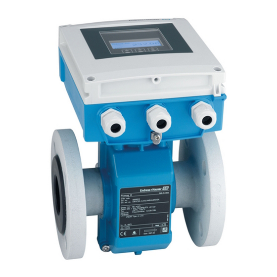
Proline Promag W 400
EtherNet/IP
Electromagnetic flowmeter
Solutions
Services
Advertisement
Chapters
Table of Contents

Related Manuals for Endress+Hauser Proline Promag W 400


Summary of Contents for Endress+Hauser Proline Promag W 400
-
Page 1: Operating Instructions
Products Solutions Services BA01214D/06/EN/03.15 71280372 Valid as of version 01.00.zz (Device firmware) Operating Instructions Proline Promag W 400 EtherNet/IP Electromagnetic flowmeter AUTHORIZED DISTRIBUTOR: InstrumentsAndControl.com Houston, Texas USA sales@InstrumentsAndControl.com 832-615-3588... - Page 2 • The manufacturer reserves the right to modify technical data without prior notice. Your Endress+Hauser Sales Center will supply you with current information and updates to these Instructions. Endress+Hauser...
-
Page 3: Table Of Contents
Proline Promag W 400 EtherNet/IP Table of contents Table of contents 6.2.2 Preparing the measuring device ..24 Document information ....6 6.2.3 Mounting the sensor . - Page 4 10.9 Simulation ......96 13.3 Endress+Hauser services ....123 10.10 Protecting settings from unauthorized...
- Page 5 14.2 Spare parts ......124 14.3 Endress+Hauser services ....124 14.4 Return .
-
Page 6: Document Information
Document information Proline Promag W 400 EtherNet/IP Document information Document function These Operating Instructions contain all the information that is required in various phases of the life cycle of the device: from product identification, incoming acceptance and storage, to mounting, connection, operation and commissioning through to troubleshooting, maintenance and disposal. -
Page 7: Symbols For Certain Types Of Information
• The W@M Device Viewer : Enter the serial number from the nameplate (www.endress.com/deviceviewer) • The Endress+Hauser Operations App: Enter the serial number from the nameplate or scan the 2-D matrix code (QR code) on the nameplate. For a detailed list of the individual documents along with the documentation code... -
Page 8: Standard Documentation
Registered trademarks EtherNet/IP Trademark of ODVA, Inc. ® Microsoft Registered trademark of the Microsoft Corporation, Redmond, Washington, USA Applicator ® , FieldCare ® , Field Xpert , HistoROM ® , Heartbeat Technology Registered or registration-pending trademarks of the Endress+Hauser Group Endress+Hauser... -
Page 9: Basic Safety Instructions
Proline Promag W 400 EtherNet/IP Basic safety instructions Basic safety instructions Requirements for the personnel The personnel for installation, commissioning, diagnostics and maintenance must fulfill the following requirements: ‣ Trained, qualified specialists must have a relevant qualification for this specific function and task ‣... -
Page 10: Workplace Safety
Verification for borderline cases: ‣ For special fluids and fluids for cleaning, Endress+Hauser is glad to provide assistance in verifying the corrosion resistance of fluid-wetted materials, but does not accept any warranty or liability as minute changes in the temperature, concentration or level of contamination in the process can alter the corrosion resistance properties. -
Page 11: Product Safety
It meets general safety standards and legal requirements. It also complies with the EC directives listed in the device-specific EC Declaration of Conformity. Endress+Hauser confirms this by affixing the CE mark to the device. -
Page 12: Product Description
Product description Proline Promag W 400 EtherNet/IP Product description The device consists of a transmitter and a sensor. Two device versions are available: • Compact version - transmitter and sensor form a mechanical unit. • Remote version - transmitter and sensor are mounted in separate locations. -
Page 13: Incoming Acceptance And Product
• If one of the conditions is not satisfied, contact your Endress+Hauser Sales Center. • Depending on the device version, the CD-ROM might not be part of the delivery! The Technical Documentation is available via the Internet or via the Endress+Hauser Operations App, see the "Product identification"... -
Page 14: Transmitter Nameplate
"Supplementary device-dependent documentation" → 8 • The W@M Device Viewer: Enter the serial number from the nameplate (www.endress.com/deviceviewer) • The Endress+Hauser Operations App: Enter the serial number from the nameplate or scan the 2-D matrix code (QR code) on the nameplate. 4.2.1... -
Page 15: Sensor Nameplate
Proline Promag W 400 EtherNet/IP Incoming acceptance and product identification 4.2.2 Sensor nameplate Order Code: Ser.No.: Ext. ord. cd.: Material: Patents Date: A0017186 3 Example of sensor nameplate Name of the sensor Manufacturing location Order code Serial number (ser. no.) Extended order code (ext. -
Page 16: Symbols On Measuring Device
Incoming acceptance and product identification Proline Promag W 400 EtherNet/IP 4.2.3 Symbols on measuring device Symbol Meaning WARNING! This symbol alerts you to a dangerous situation. Failure to avoid this situation can result in serious or fatal injury. Reference to documentation Refers to the corresponding device documentation. -
Page 17: Storage And Transport
Proline Promag W 400 EtherNet/IP Storage and transport Storage and transport Storage conditions Observe the following notes for storage: • Store in the original packaging to ensure protection from shock. • Do not remove protective covers or protective caps installed on process connections. -
Page 18: Measuring Devices With Lifting Lugs
Storage and transport Proline Promag W 400 EtherNet/IP 5.2.2 Measuring devices with lifting lugs CAUTION Special transportation instructions for devices with lifting lugs ‣ Only use the lifting lugs fitted on the device or flanges to transport the device. ‣... -
Page 19: Installation
Proline Promag W 400 EtherNet/IP Installation Installation Installation conditions 6.1.1 Mounting position Mounting location A0023343 Preferably install the sensor in an ascending pipe, and ensure a sufficient distance to the next pipe elbow: h ≥ 2 × DN To prevent measuring errors arising from accumulation of gas bubbles in the measuring tube, avoid the following mounting locations in the pipe: •... - Page 20 Installation Proline Promag W 400 EtherNet/IP A0017063 Orientation The direction of the arrow on the sensor nameplate helps you to install the sensor according to the flow direction (direction of medium flow through the piping). An optimum orientation position helps avoid gas and air accumulations and deposits in the measuring tube.
-
Page 21: Requirements From Environment And Process
Proline Promag W 400 EtherNet/IP Installation 5 × DN 2 × DN ≥ ≥ A0016275 To keep within the in-service maximum permissible errors for custody transfer no additional requirements apply with regard to the graphic illustrated above. Installation dimensions For the dimensions and installation lengths of the device, see the "Technical Information"... - Page 22 Installation Proline Promag W 400 EtherNet/IP Never install the sensor on the pump suction side in order to avoid the risk of low pressure, and thus damage to the liner. Furthermore, install pulse dampers if reciprocating, diaphragm or peristaltic pumps are used.
-
Page 23: Special Mounting Instructions
Proline Promag W 400 EtherNet/IP Installation [mbar] 8 m/s 7 m/s 6 m/s 5 m/s 4 m/s max. 8° 3 m/s 2 m/s 1 m/s d / D A0016359 6.1.3 Special mounting instructions Display protection ‣ To ensure that the optional display protection can be easily opened, maintain the following minimum head clearance: 350 mm (13.8 in) -
Page 24: Mounting The Measuring Device
Installation Proline Promag W 400 EtherNet/IP Buried applications A0017298 Mounting the measuring device 6.2.1 Required tools For transmitter • Torque wrench • For wall mounting: Open-ended wrench for hexagonal screw max. M5 • For pipe mounting: – Open-ended wrench AF 8 –... - Page 25 Proline Promag W 400 EtherNet/IP Installation 2. To ensure compliance with device specifications, install the measuring device between the pipe flanges in a way that it is centered in the measurement section. 3. If using ground disks, comply with the Installation Instructions provided.
- Page 26 Installation Proline Promag W 400 EtherNet/IP Nominal diameter Pressure rating Threaded fasteners Max. screw tightening torque [Nm] [mm] [bar] [mm] Hard rubber Polyurethane PN 16 8 × M16 PN 40 8 × M24 PN 16 8 × M20 PN 40 8 ×...
- Page 27 Proline Promag W 400 EtherNet/IP Installation Nominal diameter Pressure rating Threaded fasteners Max. screw tightening torque [Nm] [mm] [bar] [mm] Hard rubber Polyurethane PN 10 28 × M30 PN 16 28 × M36 PN 25 28 × M45 1 000 PN 6 28 ×...
- Page 28 Installation Proline Promag W 400 EtherNet/IP Nominal diameter Pressure rating Threaded fasteners Max. screw tightening torque [Nm] ([lbf · ft]) [mm] [in] [psi] [in] Hard rubber Polyurethane Class 150 12 × 7/8 101 (74) 75 (55) Class 150 12 × 7/8...
- Page 29 Proline Promag W 400 EtherNet/IP Installation Nominal diameter Threaded fasteners Max. screw tightening torque [Nm] [mm] [mm] Hard rubber Polyurethane 20 × M30 – 20 × M30 – 24 × M30 – 1 000 24 × M30 – 1 200 32 ×...
-
Page 30: Mounting The Transmitter Of The Remote Version
Installation Proline Promag W 400 EtherNet/IP Nominal diameter Pressure rating Threaded fasteners Max. screw tightening torque [Nm] [mm] [bar] [mm] Hard rubber Polyurethane 8 × M16 8 × M16 8 × M20 8 × M16 8 × M20 8 × M20 8 ×... - Page 31 Proline Promag W 400 EtherNet/IP Installation Wall mounting 17 (0.67) 14 (0.55) 5.8 (0.23) 5.8 (0.23) 149 (5.85) A0020523 7 Engineering unit mm (in) 1. Drill the holes. 2. Insert wall plugs into the drilled holes. 3. Screw in the securing screws slightly at first.
-
Page 32: Turning The Transmitter Housing
Installation Proline Promag W 400 EtherNet/IP ø TX 25 20…70 ø ( 0.79…2.75) SW 8 A0020705 8 Engineering unit mm (in) 6.2.5 Turning the transmitter housing To provide easier access to the connection compartment or display module, the transmitter housing can be turned. - Page 33 Proline Promag W 400 EtherNet/IP Installation TX 20 A0021604 4 mm A0021605 1. Loosen the fixing screws of the housing cover (when reassembling, pay attention to the tightening torque → 34). 2. Open the housing cover. 3. Unlock the display module.
-
Page 34: Turning The Display Module
Installation Proline Promag W 400 EtherNet/IP Step Fixing screw Tightening torques for housing made of: Aluminum Plastic Housing cover 2.5 Nm (1.8 lbf ft) 1 Nm (0.7 lbf ft) Smart sensor electronics module 0.6 Nm (0.4 lbf ft) Main electronics module 1.5 Nm (1.1 lbf ft) -
Page 35: Post-Installation Check
Proline Promag W 400 EtherNet/IP Installation Reassembling the transmitter housing WARNING Excessive tightening torque applied to the fixing screws! Damage to the transmitter. ‣ When reassembling, tighten the fixing screws as per the tightening torque: Step Fixing screw Tightening torque for housing made of:... -
Page 36: Electrical Connection
Electrical connection Proline Promag W 400 EtherNet/IP Electrical connection The measuring device does not have an internal circuit breaker. For this reason, assign the measuring device a switch or power-circuit breaker so that the power supply line can be easily disconnected from the mains. - Page 37 Proline Promag W 400 EtherNet/IP Electrical connection Coil current cable Standard cable (18 AWG) with common, braided copper shield ( ~ 7 mm (0.28")) 2 ×0.75 mm and individually shielded cores Conductor resistance ≤37 Ω/km (0.011 Ω/ft) Capacitance: core/core, ≤120 pF/m (37 pF/ft)
-
Page 38: Terminal Assignment
Electrical connection Proline Promag W 400 EtherNet/IP 7.1.3 Terminal assignment Transmitter EtherNet/IP connection version The sensor can be ordered with terminals or a device plug. Connection methods available Possible options for order code Power "Electrical connection" Outputs supply Terminals Terminals •... -
Page 39: Pin Assignment, Device Plug
Proline Promag W 400 EtherNet/IP Electrical connection Remote version 6 5 7 8 4 37 36 42 41 n.c. n.c. n.c. 5 7 4 37 42 41 A0020534 10 Remote version terminal assignment Transmitter wall-mount housing Sensor connection housing... -
Page 40: Shielding And Grounding
Electrical connection Proline Promag W 400 EtherNet/IP 7.1.5 Shielding and grounding 7.1.6 Requirements for the supply unit Supply voltage Transmitter Order code for "Power supply" Terminal voltage Frequency range AC100 to 240 V 50/ 60 Hz, ±4 Hz Option L AC/DC24 V 50/ 60 Hz, ±4 Hz... -
Page 41: Connecting The Measuring Device
Proline Promag W 400 EtherNet/IP Electrical connection Sensor Electrode cable Coil current cable 20 (0.79)* 20 (0.79)* 160 (6.30)* 170 (6.69)* 80 (3.15) 70 (2.76) 50 (1.97) 50 (1.97) 18.5 (0.73) 10 (0.39) 6 (0.24) 8 (0.31) ³1 (0.04) A0016489... - Page 42 Electrical connection Proline Promag W 400 EtherNet/IP 3. Connect the transmitter. TX 20 6 5 7 8 4 37 36 42 41 A0017445 13 Transmitter: main electronics module with terminals 1. Loosen the 4 fixing screws on the housing cover.
-
Page 43: Connecting The Transmitter
Proline Promag W 400 EtherNet/IP Electrical connection 6. Firmly tighten the cable glands. 7. WARNING! Housing degree of protection may be voided due to insufficient sealing of the housing. Screw in the screw without using any lubricant. The threads on the cover are coated with a dry lubricant. -
Page 44: Ensuring Potential Equalization
Electrical connection Proline Promag W 400 EtherNet/IP 7.2.3 Ensuring potential equalization Requirements CAUTION Electrode damage can result in the complete failure of the device! ‣ Same electrical potential for the fluid and sensor ‣ Remote version: same electrical potential for the sensor and transmitter ‣... - Page 45 Proline Promag W 400 EtherNet/IP Electrical connection Plastic pipe or pipe with insulating liner This connection method also applies in situations where: • The customary potential equalization is not used • Equalizing currents are present Ground cable Copper wire, at least6 mm (0.0093 in...
-
Page 46: Special Connection Instructions
Electrical connection Proline Promag W 400 EtherNet/IP Special connection instructions Hardware settings 7.4.1 Setting the device address EtherNet/IP The IP address of the measuring device can be configured for the network via DIP switches. Addressing data IP address and configuration options... -
Page 47: Ensuring The Degree Of Protection
Proline Promag W 400 EtherNet/IP Electrical connection Ensuring the degree of protection 7.5.1 Degree of protection IP66/67, Type 4X enclosure The measuring device fulfills all the requirements for the IP66/67 degree of protection, Type 4X enclosure. To guarantee IP66/67 degree of protection, Type 4X enclosure, carry out the following steps after the electrical connection: 1. - Page 48 Electrical connection Proline Promag W 400 EtherNet/IP Only for remote version: is the sensor connected to the right transmitter? Check the serial number on the nameplate of the sensor and transmitter. Does the supply voltage match the specifications on the transmitter nameplate ? ...
-
Page 49: Operation Options
Proline Promag W 400 EtherNet/IP Operation options Operation options Overview of operation options A0019091 Local operation via display module Computer with Web browser (e.g. Internet Explorer) or with operating tool (e.g. FieldCare, AMS Device Manager, SIMATIC PDM) Control system (e.g. PLC) For custody transfer, once the device has been put into circulation or sealed, its operation is restricted. -
Page 50: Structure And Function Of The Operating Menu
Operation options Proline Promag W 400 EtherNet/IP Structure and function of the operating menu 8.2.1 Structure of the operating menu For an overview of the operating menu with menus and parameters → 162 Operating menu for operators and maintenances... -
Page 51: Operating Philosophy
Proline Promag W 400 EtherNet/IP Operation options 8.2.2 Operating philosophy The individual parts of the operating menu are assigned to certain user roles (operator, maintenance etc.). Each user role contains typical tasks within the device lifecycle. For custody transfer, once the device has been put into circulation or sealed, its operation is restricted. -
Page 52: Access To The Operating Menu Via The Local Display
Operation options Proline Promag W 400 EtherNet/IP Access to the operating menu via the local display 8.3.1 Operational display X X X X X X X 1120.50 A0016502 Operational display Device tag Status area Display area for measured values (4-line) Operating elements →... -
Page 53: Navigation View
Proline Promag W 400 EtherNet/IP Operation options Mass flow Totalizer The measurement channel number indicates which of the three totalizers is displayed. Output The measurement channel number indicates which of the outputs is displayed. Status input Measurement channel numbers... - Page 54 Operation options Proline Promag W 400 EtherNet/IP Examples / ../ Display / ../ Display For more information about the menu icons, refer to the "Display area" section → 54 Status area The following appears in the status area of the navigation view in the top right corner: •...
-
Page 55: Editing View
Proline Promag W 400 EtherNet/IP Operation options Locking Symbol Meaning Parameter locked When displayed in front of a parameter name, indicates that the parameter is locked. • By a user-specific access code • By the hardware write protection switch Wizard operation... - Page 56 Operation options Proline Promag W 400 EtherNet/IP Exits the input without applying the changes. Clears all entered characters. Text editor Symbol Meaning Toggle • Between upper-case and lower-case letters • For entering numbers • For entering special characters Selection of letters from A to Z.
-
Page 57: Operating Elements
Proline Promag W 400 EtherNet/IP Operation options 8.3.4 Operating elements Meaning Minus key In a menu, submenu Moves the selection bar upwards in a choose list. With a Wizard Confirms the parameter value and goes to the previous parameter. With a text and numeric editor In the input mask, moves the selection bar to the left (backwards). - Page 58 Operation options Proline Promag W 400 EtherNet/IP • Setup • Simulation Calling up and closing the context menu The user is in the operational display. 1. Press for 2 s. The context menu opens. XXXXXXXXXX 20.50 Setup Simulation A0017421-EN 2.
-
Page 59: Navigating And Selecting From List
Proline Promag W 400 EtherNet/IP Operation options 8.3.6 Navigating and selecting from list Different operating elements are used to navigate through the operating menu. The navigation path is displayed on the left in the header. Icons are displayed in front of the individual menus. -
Page 60: Calling Up Help Text
Operation options Proline Promag W 400 EtherNet/IP The direct access code consists of a 4-digit number and the channel number, which identifies the channel of a process variable: e.g. 0914-1. In the navigation view, this appears on the right-hand side in the header of the selected parameter. -
Page 61: Changing The Parameters
Proline Promag W 400 EtherNet/IP Operation options 8.3.9 Changing the parameters For a description of the editing display - consisting of text editor and numeric editor - with symbols → 55, for a description of the operating elements → 57 Example: Changing the tag name in the "Tag description"... -
Page 62: User Roles And Related Access Authorization
Operation options Proline Promag W 400 EtherNet/IP Ent. access code Invalid or out of range input value Min:0 Max:9999 A0014049-EN 8.3.10 User roles and related access authorization The two user roles "Operator" and "Maintenance" have different write access to the parameters if the customer defines a user-specific access code. -
Page 63: Access To The Operating Menu Via The Web Browser
Proline Promag W 400 EtherNet/IP Operation options Switching on the keypad lock The keypad lock is switched on automatically: • Each time the device is restarted. • If the device has not been operated for longer than one minute in the measured value display. -
Page 64: Establishing A Connection
Operation options Proline Promag W 400 EtherNet/IP Computer settings User rights User rights are required for TCP/IP and proxy server settings (for changes to the IP address, subnet mask etc.). Proxy server settings of the The Web browser setting Use proxy server for LAN must be disabled. -
Page 65: Logging On
Proline Promag W 400 EtherNet/IP Operation options 2. If a 2nd network card is not used: all the applications on the notebook should be closed, or all the applications that require the Internet or network, such as e-mail, SAP applications, Internet or Windows Explorer, i.e. close all open Internet browsers. -
Page 66: User Interface
Operation options Proline Promag W 400 EtherNet/IP 8.4.5 User interface A0017757-EN Picture of device Function row with 6 functions Device tag Header Working area Navigation area Header The following information appears in the header: • Device tag • Device status with status signal → 111 •... -
Page 67: Disabling The Web Server
Proline Promag W 400 EtherNet/IP Operation options Working area Depending on the selected function and the related submenus, various actions can be performed in this area: • Configuring parameters • Reading measured values • Calling up help text • Starting an upload/download 8.4.6... -
Page 68: Connecting The Operating Tool
FieldCare Function scope FDT-based plant asset management tool from Endress+Hauser. It can configure all smart field devices in a system and helps you manage them. By using the status information, it is also a simple but effective way of checking their status and condition. - Page 69 Proline Promag W 400 EtherNet/IP Operation options 6. Enter the device address in the IP address field: 192.168.1.212 and press Enter to confirm. 7. Establish the online connection to the device. For details, see Operating Instructions BA00027S and BA00059S User interface...
-
Page 70: System Integration
System integration Proline Promag W 400 EtherNet/IP System integration Overview of device description files 9.1.1 Current version data for the device Firmware version 01.01.zz • On the title page of the Operating instructions • On transmitter nameplate → 13 •... -
Page 71: Cyclic Data Transmission
Proline Promag W 400 EtherNet/IP System integration Cyclic data transmission Cyclic data transmission when using the device master file (GSD). 9.4.1 Block model The block model shows which input and output data the measuring device makes available for implicit messaging. Cyclical data exchange is performed using an EtherNet/IP scanner, e.g. - Page 72 System integration Proline Promag W 400 EtherNet/IP Configuration 5: Exclusive Owner Multicast Input Assembly Fix Instance Size [byte] min. RPI (ms) Input Assembly Configurable Configuration 0 x 69 – – Output Assembly Fix O → T Configuration 0 x 66 Input Assembly Fix T →...
- Page 73 Proline Promag W 400 EtherNet/IP System integration Name Description Byte 10. Totalizer 2 37 to 40 11. Totalizer 3 41 to 44 Structure: Code, number, description (e.g.: 16777265 F882 input signal) Detailed description • Diagnostic information → 114 • Information events → 118...
- Page 74 System integration Proline Promag W 400 EtherNet/IP Name Description (format) Byte Value 8. Not used – 9. Not used 2 to 4 0 to 8 – 10. Control totalizer 1 (integer) 5 to 6 0 to 8 • 32226: Add •...
-
Page 75: Commissioning
Proline Promag W 400 EtherNet/IP Commissioning Commissioning 10.1 Function check Before commissioning the measuring device: ‣ Make sure that the post-installation and post-connection checks have been performed. • "Post-installation check" checklist → 35 • "Post-connection check" checklist → 47 10.2... -
Page 76: Configuring The Measuring Device
Commissioning Proline Promag W 400 EtherNet/IP X X X X X X X 20.50 Main menu 0104-1 Language English Operation Setup Language 0104-1 English à Deutsch Español Français Language 0104-1 à English Deutsch Español Français Hauptmenü 0104-1 Sprache Deutsch Betrieb... - Page 77 Proline Promag W 400 EtherNet/IP Commissioning Setup Device tag ‣ System units Volume flow unit Volume unit Conductivity unit Temperature unit Mass flow unit Mass unit Density unit ‣ Communication MAC address Default network settings DHCP client IP address...
- Page 78 Commissioning Proline Promag W 400 EtherNet/IP 100% bargraph value 3 Value 4 display ‣ Low flow cut off Assign process variable On value low flow cutoff Off value low flow cutoff Pressure shock suppression ‣ Empty pipe detection Empty pipe detection...
- Page 79 Proline Promag W 400 EtherNet/IP Commissioning 100% bargraph value 1 Decimal places 1 Value 2 display Decimal places 2 Value 3 display 0% bargraph value 3 100% bargraph value 3 Decimal places 3 Value 4 display Decimal places 4 Display language...
-
Page 80: Defining The Tag Name
Commissioning Proline Promag W 400 EtherNet/IP ECC cleaning cycle ECC Polarity ‣ Administration ‣ Define access code Define access code Confirm access code Device reset 10.6.1 Defining the tag name To enable fast identification of the measuring point within the system, you can enter a unique designation using the Device tag parameter and thus change the factory setting. - Page 81 Proline Promag W 400 EtherNet/IP Commissioning ‣ System units Volume flow unit Volume unit Conductivity unit Temperature unit Mass flow unit Mass unit Density unit Corrected volume flow unit Corrected volume unit Parameter overview with brief description Parameter Description Selection...
-
Page 82: Configuring The Communication
Commissioning Proline Promag W 400 EtherNet/IP Parameter Description Selection Factory setting Mass unit Select mass unit. Unit choose list Country-specific: • kg Result • lb The selected unit is taken from: Mass flow unit parameter Density unit Select density unit. -
Page 83: Configuring The Local Display
Proline Promag W 400 EtherNet/IP Commissioning Parameter Description User interface / Selection / Factory setting User entry IP address IP address of the Web server of the 4 octet: 0 to 255 (in the 192.168.1.212 measuring device. particular octet) Subnet mask Displays the subnet mask. -
Page 84: Configuring The Low Flow Cut Off
Commissioning Proline Promag W 400 EtherNet/IP Parameter overview with brief description Parameter Prerequsite Description Selection / User Factory setting entry Format display – Select how measured values • 1 value, max. size 1 value, max. size are shown on the display. • 1 bargraph + 1 value •... - Page 85 Proline Promag W 400 EtherNet/IP Commissioning Structure of the wizard Assign variable Volume flow Mass flow On value Off value Pres. shock sup. End of wizard A0020524-EN 25 "Low flow cut off" wizard in the "Setup" menu Parameter overview with brief description...
-
Page 86: Configuring Empty Pipe Detection
Commissioning Proline Promag W 400 EtherNet/IP 10.6.6 Configuring empty pipe detection The Empty pipe detection wizard guides you systematically through all the parameters that have to be set for configuring the low flow cut off. Navigation "Setup" menu → Empty pipe detection Structure of the wizard Empty pipe det. -
Page 87: Advanced Settings
Proline Promag W 400 EtherNet/IP Commissioning 10.7 Advanced settings The Advanced setup submenu with its submenus contains parameters for specific settings. Navigation to the "Advanced setup" submenu X X X X X X X 20.50 0104-1 Main menu Language English Display/operat. - Page 88 Commissioning Proline Promag W 400 EtherNet/IP Totalizer operation mode Failure mode ‣ Display Format display Value 1 display 0% bargraph value 1 100% bargraph value 1 Decimal places 1 Value 2 display Decimal places 2 Value 3 display 0% bargraph value 3...
-
Page 89: Carrying Out A Sensor Adjustment
Proline Promag W 400 EtherNet/IP Commissioning ECC duration ECC recovery time ECC cleaning cycle ECC Polarity ‣ Administration ‣ Define access code Define access code Confirm access code Device reset 10.7.1 Carrying out a sensor adjustment The Sensor adjustment submenu contains parameters that pertain to the functionality of the sensor. - Page 90 Commissioning Proline Promag W 400 EtherNet/IP Totalizer operation mode Failure mode Parameter overview with brief description Parameter Description Selection Factory setting Assign process variable Select process variable for totalizer. • Off Volume flow • Volume flow • Mass flow Unit totalizer Select process variable totalizer unit.
-
Page 91: Carrying Out Additional Display Configurations
Proline Promag W 400 EtherNet/IP Commissioning 10.7.3 Carrying out additional display configurations In the Display submenu you can set all the parameters associated with the configuration of the local display. Navigation "Setup" menu → Advanced setup → Display ‣ Display... - Page 92 Commissioning Proline Promag W 400 EtherNet/IP Parameter overview with brief description Parameter Prerequsite Description Selection / User Factory setting entry Format display – Select how measured values • 1 value, max. size 1 value, max. size are shown on the display. • 1 bargraph + 1 value •...
-
Page 93: Performing Electrode Cleaning
Proline Promag W 400 EtherNet/IP Commissioning Parameter Prerequsite Description Selection / User Factory setting entry Display language – Set display language. • English English • Deutsch (alternatively, the • Français ordered language is • Español preset in the device) • Italiano • Nederlands •... -
Page 94: Administration Configuration
Commissioning Proline Promag W 400 EtherNet/IP ECC cleaning cycle ECC Polarity Parameter overview with brief description Parameter Description Selection / User entry / User Factory setting interface Electrode cleaning circuit Enable the cyclic electrode cleaning circuit. • Off • On ECC duration Enter the duration of electrode cleaning in 0.01 to 30 s... -
Page 95: Function Range Of "Configuration Management" Parameter
Proline Promag W 400 EtherNet/IP Commissioning Navigation "Setup" menu → Advanced setup → Configuration backup display ‣ Configuration backup display Operating time Last backup Configuration management Comparison result Parameter overview with brief description Parameter Prerequsite Description User interface / Factory setting... -
Page 96: Simulation
Commissioning Proline Promag W 400 EtherNet/IP Options Description Compare The device configuration saved in the display module is compared with the current device configuration of the integrated HistoROM. Clear backup data The backup copy of the device configuration is deleted from the display module of the device. -
Page 97: Protecting Settings From Unauthorized
Proline Promag W 400 EtherNet/IP Commissioning Parameter Prerequsite Description Selection / User Factory setting entry Diagnostic event category – Select the category of the • Sensor Process diagnostic event. • Electronics • Configuration • Process Simulation diagnostic event – Switch simulation of the •... -
Page 98: Write Protection Via Write Protection
Commissioning Proline Promag W 400 EtherNet/IP parameters automatically after 60 s if the user skips back to the operational display mode from the navigation and editing view. • If write access is activated via access code, it can be also be deactivated only via the access code →... - Page 99 Proline Promag W 400 EtherNet/IP Commissioning 2. Setting the write protection switch (WP) on the main electronics module to the ON position enables the hardware write protection. Setting the write protection switch (WP) on the main electronics module to the OFF position (factory setting) disables the hardware write protection.
-
Page 100: Operation
Operation Proline Promag W 400 EtherNet/IP Operation 11.1 Read out and modify current Ethernet settings If the Ethernet settings such as the IP address of the measuring device are unknown, they can be read out and modified as explained in the following example for an IP address. -
Page 101: Adjusting The Operating Language
Proline Promag W 400 EtherNet/IP Operation Function scope of "Locking status" parameter Options Description None The access status displayed in "Access status display" parameter applies → 62. Only appears on local display. Hardware locked The DIP switch for hardware locking is activated on the main electronics module. -
Page 102: Totalizer
Operation Proline Promag W 400 EtherNet/IP 11.5.2 Totalizer The Totalizer submenu contains all the parameters needed to display the current measured values for every totalizer. Navigation "Diagnostics" menu → Measured values → Totalizer ‣ Totalizer Totalizer value 1 to 3... -
Page 103: Showing Data Logging
Proline Promag W 400 EtherNet/IP Operation Function scope of "Reset all totalizers" parameter Options Description Reset + totalize Resets all totalizers to 0 and restarts the totaling process. This deletes all the flow values previously totalized. Navigation "Operation" menu → Operation ‣... - Page 104 Operation Proline Promag W 400 EtherNet/IP • x-axis: depending on the number of channels selected displays 250 to 1000 measured values of a process variable. • y-axis: displays the approximate measured value span and constantly adapts this to the ongoing measurement.
-
Page 105: Diagnostics And Troubleshooting
Proline Promag W 400 EtherNet/IP Diagnostics and troubleshooting Diagnostics and troubleshooting 12.1 General troubleshooting For local display Problem Possible causes Remedial action Local display dark and no output Supply voltage does not match that Apply the correct supply voltage . - Page 106 Diagnostics and troubleshooting Proline Promag W 400 EtherNet/IP For access Problem Possible causes Remedial action No write access to parameters Hardware write protection enabled Set the write protection switch on the main electronics module to the OFF position . No write access to parameters Current user role has limited access 1.
-
Page 107: Diagnostic Information Via Light Emitting
Proline Promag W 400 EtherNet/IP Diagnostics and troubleshooting 12.2 Diagnostic information via light emitting diodes 12.2.1 Transmitter Various light emitting diodes (LEDs) on the main electronics module of the transmitter provide information on device status. Color Meaning Power Supply voltage is off or too low... -
Page 108: Diagnostic Information On Local Display
Diagnostics and troubleshooting Proline Promag W 400 EtherNet/IP 12.3 Diagnostic information on local display 12.3.1 Diagnostic message Faults detected by the self-monitoring system of the measuring device are displayed as a diagnostic message in alternation with the operational display. Operational display in alarm condition... - Page 109 Proline Promag W 400 EtherNet/IP Diagnostics and troubleshooting Diagnostic behavior Symbol Meaning Alarm • Measurement is interrupted. • Signal outputs and totalizers assume the defined alarm condition. • A diagnostic message is generated. A0013961 • The background lighting changes to red.
-
Page 110: Calling Up Remedial Measures
Diagnostics and troubleshooting Proline Promag W 400 EtherNet/IP 12.3.2 Calling up remedial measures X X X X X X X X X X X X X X 20.50 S801 Supply voltage Menu Diagnostic list Diagnostics 1 S801 Supply voltage Diagnostics 2... -
Page 111: 12.4 Diagnostic Information In The Web Browser
Proline Promag W 400 EtherNet/IP Diagnostics and troubleshooting 12.4 Diagnostic information in the Web browser 12.4.1 Diagnostic options Any faults detected by the measuring device are displayed in the Web browser on the home page once the user has logged on. -
Page 112: Diagnostic Information In Fieldcare
Diagnostics and troubleshooting Proline Promag W 400 EtherNet/IP 12.5 Diagnostic information in FieldCare 12.5.1 Diagnostic options Any faults detected by the measuring device are displayed on the home page of the operating tool once the connection has been established. Xxxxxx/…/…/... -
Page 113: Calling Up Remedy Information
Proline Promag W 400 EtherNet/IP Diagnostics and troubleshooting 12.5.2 Calling up remedy information Remedy information is provided for every diagnostic event to ensure that problems can be rectified quickly: • On the home page Remedy information is displayed in a separate field below the diagnostics information. -
Page 114: Overview Of Diagnostic Information
Diagnostics and troubleshooting Proline Promag W 400 EtherNet/IP Options Description Logbook entry only The device continues to measure. The diagnostic message is entered in the Event logbook (events list) submenu only and is not displayed in alternation with the measured value display. - Page 115 Proline Promag W 400 EtherNet/IP Diagnostics and troubleshooting Diagnostic Short text Remedy instructions Status Diagnostic number signal behavior [from the [from the factory] factory] Device verification Device verification active, please Warning active wait. Electronic failure 1. Reset device 2. Contact service...
-
Page 116: Pending Diagnostic Events
Diagnostics and troubleshooting Proline Promag W 400 EtherNet/IP Diagnostic Short text Remedy instructions Status Diagnostic number signal behavior [from the [from the factory] factory] Process limit Low flow cut off active! Warning 1. Check low flow cut off configuration Empty pipe 1. -
Page 117: 12.10 Diagnostic List
Proline Promag W 400 EtherNet/IP Diagnostics and troubleshooting Parameter overview with brief description Parameter Prerequsite Description User interface Factory setting Actual diagnostics 1 diagnostic event has Displays the current diagnostic Symbol for diagnostic – occurred. event along with the behavior, diagnostic diagnostic information. -
Page 118: 12.11.2 Filtering The Event Logbook
Diagnostics and troubleshooting Proline Promag W 400 EtherNet/IP The event history includes entries for: • Diagnostic events → 114 • Information events → 118 In addition to the operation time of its occurrence, each event is also assigned a symbol that indicates whether the event has occurred or is ended: •... -
Page 119: 12.12 Resetting The Measuring Device
Proline Promag W 400 EtherNet/IP Diagnostics and troubleshooting Info number Info name I1189 Backup compared I1256 Display: access status changed I1264 Safety sequence aborted I1335 Firmware changed I1351 Empty pipe detection adjustment failure I1353 Empty pipe detection adjustment ok I1361... -
Page 120: 12.12.1 Function Scope Of "Device Reset" Parameter
Diagnostics and troubleshooting Proline Promag W 400 EtherNet/IP 12.12.1 Function scope of "Device reset" parameter Options Description Cancel No action is executed and the user exits the parameter. To delivery settings Every parameter for which a customer-specific default setting was ordered is reset to this customer-specific value. - Page 121 Proline Promag W 400 EtherNet/IP Diagnostics and troubleshooting Parameter overview with brief description Parameter Description User interface / User entry Factory setting Device tag Enter the name for the measuring point. Max. 32 characters, such as Promag 400 letters, numbers or special characters (e.g.
-
Page 122: 12.14 Firmware History
"Manufacturer' s information" document. The manufacturer' s information is available: • In the Download Area of the Endress+Hauser Internet site: www.endress.com → Download • Specify the following details: –... -
Page 123: Maintenance
Replacement seals (accessory) → 160 13.2 Measuring and test equipment Endress+Hauser offers a wide variety of measuring and test equipment, such as W@M or device tests. Your Endress+Hauser Sales Center can provide detailed information on the services. For a list of some of the measuring and test equipment, refer to the "Accessories"... -
Page 124: Repair
• Spare parts are grouped into logical kits with the associated Installation Instructions. • Repairs are carried out by Endress+Hauser Service or by correspondingly trained customers. • Certified devices can be converted into other certified devices by Endress+Hauser Service or at the factory only. Notes for repair and conversion For repair and modification of a measuring device, observe the following notes: •... -
Page 125: Disposing Of The Measuring Device
Proline Promag W 400 EtherNet/IP Repair 2. WARNING! Danger to persons from process conditions. Beware of hazardous process conditions such as pressure in the measuring device, high temperatures or aggressive fluids. Carry out the mounting and connection steps from the chapters "Mounting the measuring device"... -
Page 126: Accessories
Various accessories, which can be ordered with the device or subsequently from Endress +Hauser, are available for the device. Detailed information on the order code in question is available from your local Endress+Hauser sales center or on the product page of the Endress+Hauser website: www.endress.com. -
Page 127: System Components
The application already contains the data of your Endress+Hauser device. Endress +Hauser also takes care of maintaining and updating the data records. -
Page 128: Technical Data
Technical data Proline Promag W 400 EtherNet/IP Technical data 16.1 Application The measuring device described in these Instructions is intended only for flow measurement of liquids with a minimum conductivity of 5 μS/cm. Depending on the version ordered, the measuring device can also measure potentially explosive, flammable, poisonous and oxidizing media. - Page 129 Proline Promag W 400 EtherNet/IP Technical data Nominal Recommended Factory settings diameter flow Full scale value current Min./max. full scale value Pulse value Low flow cut off output (v ~ 0.3/10 m/s) (~ 2 pulse/s) (v ~ 0.04 m/s) (v ~ 2.5 m/s)
- Page 130 Technical data Proline Promag W 400 EtherNet/IP Nominal Recommended Factory settings diameter flow Full scale value current Min./max. full scale value Pulse value Low flow cut off output (v ~ 0.3/10 m/s) (~ 2 pulse/s) (v ~ 0.04 m/s) (v ~ 2.5 m/s)
-
Page 131: Output
Input signal External measured values Various pressure transmitters and temperature measuring devices can be ordered from Endress+Hauser: see "Accessories" section → 127 It is recommended to read in external measured values to calculate the following measured variables: Corrected volume flow... - Page 132 Technical data Proline Promag W 400 EtherNet/IP Light emitting diodes (LED) Status information Status indicated by various light emitting diodes The following information is displayed depending on the device version: • Supply voltage active • Data transmission active • Device alarm/error has occurred •...
- Page 133 Proline Promag W 400 EtherNet/IP Technical data Instance configuration: 0x69 O → T configuration: 0x66 T → O configuration: 0x64 Input only Multicast Instance Size [byte] Instance configuration: 0x68 O → T configuration: 0xC7 T → O configuration: 0x64 Input only Multicast...
-
Page 134: Power Supply
Technical data Proline Promag W 400 EtherNet/IP Configurable Input Assembly • Volume flow • Mass flow • Electronic temperature • Conductivity • Totalizer 1 to 3 • Flow velocity • Volume flow unit • Mass flow unit • Temperature unit •... -
Page 135: Performance Characteristics
Proline Promag W 400 EtherNet/IP Technical data Current consumption Transmitter Order code for "Power supply" Maximum Maximum Current consumption switch-on current Option L: AC 100 to 240 V 145 mA 25 A (< 5 ms) Option L: AC/DC 24 V 350 mA 27 A (<... - Page 136 Technical data Proline Promag W 400 EtherNet/IP Installation • Inlet run > 10 × DN • Outlet run > 5 × DN • Sensor and transmitter grounded. • The sensor is centered in the pipe. No special requirements must be observed at the inlet and outlet runs to keep within the in-service maximum permissible errors for custody transfer.
-
Page 137: Installation
Atmosphere If a plastic transmitter housing is permanently exposed to certain steam and air mixtures, this can damage the housing. If you are unsure, please contact your Endress+Hauser Sales Center for clarification. Degree of protection Transmitter • As standard: IP66/67, type 4X enclosure •... -
Page 138: Process
Technical data Proline Promag W 400 EtherNet/IP Sensor • As standard: IP66/67, type 4X enclosure • Optionally available for remote version: – IP66/67, type 4X enclosure; fully welded, with protective varnish EN ISO 12944 C5-M. Suitable for use in corrosive atmospheres. -
Page 139: 16.10 Mechanical Construction
Proline Promag W 400 EtherNet/IP Technical data Pressure-temperature An overview of the pressure-temperature ratings for the process connections is ratings provided in the "Technical Information" document Pressure tightness Liner: hard rubber Nominal diameter Limit values for absolute pressure in [mbar] ([psi]) for fluid temperatures:... - Page 140 Technical data Proline Promag W 400 EtherNet/IP Weight in SI units Standard version EN 1092-1 (DIN 2501) Pressure rating Weight [kg] [mm] Order code for "Housing", option M, Q Order code for "Housing", option A, R Polycarbonate plastic Aluminum, AlSi10Mg, coated...
- Page 141 Proline Promag W 400 EtherNet/IP Technical data JIS B2220, 10K Weight [kg] [mm] Order code for "Housing", option M, Q Order code for "Housing", option A, R Polycarbonate plastic Aluminum, AlSi10Mg, coated 11.7 13.7 19.7 23.7 40.7 68.7 70.7 Order code for "Design", option A Option A "Insertion length short;...
- Page 142 Technical data Proline Promag W 400 EtherNet/IP AS 2129, Table E Weight [kg] [mm] Order code for "Housing", option M, Q Order code for "Housing", option A, R Polycarbonate plastic Aluminum, AlSi10Mg, coated 261.7 347.7 434.7 494.7 691.7 1 000 762.7...
- Page 143 Proline Promag W 400 EtherNet/IP Technical data EN 1092-1 (DIN 2501) Pressure rating Weight [kg] [mm] Order code for "Housing", option M, Q Order code for "Housing", option A, R Polycarbonate plastic Aluminum, AlSi10Mg, coated PN 16 22.7 PN 16 27.7...
- Page 144 Technical data Proline Promag W 400 EtherNet/IP Weight in US units Standard version ASME B16.5, Class 150 Weight [lbs] [in] Order code for "Housing", option M, Q Order code for "Housing", option A, R Polycarbonate plastic Aluminum, AlSi10Mg, coated 12.5 1½...
- Page 145 Proline Promag W 400 EtherNet/IP Technical data Order code for "Design", option A Option A "Insertion length short; ISO/DVGW to DN400, DN450-2000 1:1" ASME B16.5, Class 150 Weight [lbs] [in] Order code for "Housing", option M, Q Order code for "Housing", option A, R...
- Page 146 Technical data Proline Promag W 400 EtherNet/IP Transmitter remote version Wall-mount housing Depends on the material of the wall-mount housing: • Polycarbonate plastic: 1.3 kg (2.9 lb) • Aluminum, AlSi10Mg, coated: 2.0 kg (4.4 lb) Sensor remote version Weight data: •...
- Page 147 Proline Promag W 400 EtherNet/IP Technical data AS 4087, PN 16 Weight [mm] [kg] JIS B2220, 10K Weight [mm] [kg] Order code for "Design", option A Option A "Insertion length short; ISO/DVGW to DN400, DN450-2000 1:1" EN 1092-1 (DIN 2501)
- Page 148 Technical data Proline Promag W 400 EtherNet/IP AS 2129, Table E Weight [mm] [kg] 1 000 1 200 1 237 AS 4087, PN 16 Weight [mm] [kg] 1 000 1 200 1 219 Order code for "Calibration flow", options H and K or order code for "Sensor option", option...
- Page 149 Proline Promag W 400 EtherNet/IP Technical data EN 1092-1 (DIN 2501) Pressure rating [kg] [mm] PN 16 PN 10 PN 10 PN 10 AS 4087, PN 16 [kg] [mm] JIS B2220, 10K Weight [mm] [kg] Weight in US units Standard version ASME B16.5, Class 150...
- Page 150 Technical data Proline Promag W 400 EtherNet/IP ASME B16.5, Class 150 Weight [in] [lbs] AWWA C207, Class D Weight [in] [lbs] 1 010 1 208 1 760 1 980 2 421 3 083 4 847 5 949 8 154 9 036 10 139 Order code for "Design", option A...
- Page 151 Proline Promag W 400 EtherNet/IP Technical data AWWA C207, Class D Weight [in] [lbs] 1 477 1 987 1 273 3 515 4 699 5 662 6 864 Order code for "Sensor option", option CA Option CA "IP66/67, Type 4X, fully welded; corrosion protection EN ISO 12944 C5-M"...
- Page 152 Technical data Proline Promag W 400 EtherNet/IP Nominal diameter Pressure rating Measuring tube internal diameter EN (DIN) ASME AS 2129 Hard rubber Polyurethane AWWA AS 4087 [mm] [in] [mm] [in] [mm] [in] – – PN 16 – 15.4 – –...
- Page 153 Proline Promag W 400 EtherNet/IP Technical data Remote version (wall-mount housing) • Order code for "Housing", option P "Compact, aluminum coated": Aluminum, AlSi10Mg, coated • Order code for "Housing", option N: polycarbonate plastic • Window material: – For order code for "Housing", option P: glass –...
- Page 154 Technical data Proline Promag W 400 EtherNet/IP Sensor housing • DN 25 to 300 (1 to 12"): – Aluminum, AlSi10Mg, coated – Carbon steel with Al/Zn protective coating • DN 50 to 300 (2 to 12"): Carbon steel with protective varnish (IP68) •...
- Page 155 Proline Promag W 400 EtherNet/IP Technical data ASME B16.5 • DN 25 to 1200 (1 to 48"): Stainless steel, F316L similar to 1.4404 • DN 25 to 300 (1 to 12") Carbon steel, A105 similar to 1.0432 • DN 350 to 1200 (14 to 48")
-
Page 156: 16.11 Operability
Technical data Proline Promag W 400 EtherNet/IP Process connections • EN 1092-1 (DIN 2501) – DN ≤ 300: fixed flange (PN 10/16/25/40) = form A – DN ≥ 350: fixed flange (PN 6/10/16/25) = flat face – DN 450 to 2000 : fixed flange (PN 6/10/16) = flat face •... - Page 157 Proline Promag W 400 EtherNet/IP Technical data Operating elements External operation via touch control; 3 optical keys: Additional functionality • Data backup function The device configuration can be saved in the display module. • Data comparison function The device configuration saved in the display module can be compared to the current device configuration.
-
Page 158: 16.12 Certificates And Approvals
EC Directives. These are listed in the corresponding EC Declaration of Conformity along with the standards applied. Endress+Hauser confirms successful testing of the device by affixing to it the CE mark. C-Tick symbol The measuring system meets the EMC requirements of the "Australian Communications and Media Authority (ACMA)". -
Page 159: 16.13 Application Packages
The application packages can be ordered with the device or subsequently from Endress+Hauser. Detailed information on the order code in question is available from your local Endress+Hauser sales center or on the product page of the Endress+Hauser website: www.endress.com. -
Page 160: 16.14 Accessories
• The W@M Device Viewer : Enter the serial number from the nameplate (www.endress.com/deviceviewer) • The Endress+Hauser Operations App: Enter the serial number from the nameplate or scan the 2-D matrix code (QR code) on the nameplate. Standard documentation... - Page 161 Proline Promag W 400 EtherNet/IP Technical data Technical Information Measuring device Documentation code Promag W 400 TI01046D Supplementary device- Special documentation dependent documentation Contents Documentation code Heartbeat Technology SD01183D Information on Custody Transfer Measurement SD01230D Installation Instructions Contents Documentation code ...
-
Page 162: Appendix
Appendix Proline Promag W 400 EtherNet/IP Appendix 17.1 Overview of the operating menu The following graphic provides an overview of the entire operating menu structure with its menus, submenus and parameters. The page reference indicates where a description of the parameter can be found in the manual. -
Page 163: Setup" Menu
Proline Promag W 400 EtherNet/IP Appendix Backlight → 93 Display interval → 93 ‣ Totalizer handling Control Totalizer 1 to 3 → 103 Preset value 1 to 3 → 103 Reset all totalizers → 103 17.1.2... - Page 164 Appendix Proline Promag W 400 EtherNet/IP Subnet mask → 83 Default gateway → 83 ‣ Display → 83 Format display → 84 Value 1 display → 84 → 84 0% bargraph value 1 100% bargraph value 1 →...
- Page 165 Proline Promag W 400 EtherNet/IP Appendix ‣ Sensor adjustment → 89 Installation direction → 89 ‣ Totalizer 1 to 3 → 89 Assign process variable → 90 Unit totalizer → 90 Totalizer operation mode → 90 Failure mode →...
-
Page 166: Diagnostics" Menu
Appendix Proline Promag W 400 EtherNet/IP Header text → 93 Separator → 93 Backlight → 93 ‣ Electrode cleaning circuit → 93 Electrode cleaning circuit → 94 → 94 ECC duration ECC recovery time →... - Page 167 Proline Promag W 400 EtherNet/IP Appendix Diagnostics 3 Diagnostics 4 Diagnostics 5 ‣ Event logbook Filter options ‣ Event list ‣ Device information → 120 Device tag → 121 Serial number → 121 → 121 Firmware version →...
- Page 168 Appendix Proline Promag W 400 EtherNet/IP Mass flow → 101 Conductivity → 101 ‣ Totalizer → 89 Totalizer value 1 to 3 → 102 Totalizer overflow 1 to 3 → 102 ‣ → 103...
- Page 169 Proline Promag W 400 EtherNet/IP Appendix External device information External reference voltage 1 External reference voltage 2 Start verification Progress Status Overall result ‣ Verification results Date/time Verification ID Operating time Overall result Sensor Sensor electronic module I/O module ‣...
-
Page 170: Expert" Menu
Appendix Proline Promag W 400 EtherNet/IP Diagnostic event category → 97 Simulation diagnostic event → 97 17.1.4 "Expert" menu The following tables provide an overview of the Expert menu with its submenus and parameters. The direct access code to the parameter is given in brackets. The page reference indicates where a description of the parameter can be found in the manual. - Page 171 Proline Promag W 400 EtherNet/IP Appendix 0% bargraph value 1 (0123) → 84 100% bargraph value 1 (0125) → 84 Decimal places 1 (0095) → 92 Value 2 display (0108) → 84 Decimal places 2 (0117) →...
- Page 172 Appendix Proline Promag W 400 EtherNet/IP Assign behavior of diagnostic no. 833 (0682) Assign behavior of diagnostic no. 862 (0745) Assign behavior of diagnostic no. 937 (0743) Assign behavior of diagnostic no. 302 (0739) ‣ → 94 Administration ‣...
-
Page 173: System Units
Proline Promag W 400 EtherNet/IP Appendix ‣ System units → 80 Volume flow unit (0553) → 81 Volume unit (0563) → 81 Conductivity unit (0582) → 81 Temperature unit (0557) → 81 Mass flow unit (0554) →... - Page 174 Appendix Proline Promag W 400 EtherNet/IP Off value low flow cutoff (1804) → 85 Pressure shock suppression (1806) → 85 ‣ Empty pipe detection → 86 Empty pipe detection (1860) → 86 Switch point empty pipe detection →...
-
Page 175: Communication
Proline Promag W 400 EtherNet/IP Appendix Measuring period (6536) ‣ Process variable adjustment Volume flow offset (1831) Volume flow factor (1832) Mass flow offset (1841) Mass flow factor (1846) Conductivity offset (1848) Conductivity factor (1849) ‣ Calibration Nominal diameter (2807) - Page 176 Appendix Proline Promag W 400 EtherNet/IP Web server functionality (7222) → 67 ‣ Configurable input assembly Input assembly position 1 (7402) Input assembly position 2 (7413) Input assembly position 3 (7415) Input assembly position 4 (7416) Input assembly position 5 (7417)
- Page 177 Proline Promag W 400 EtherNet/IP Appendix ‣ Application Reset all totalizers (2806) → 103 ‣ Totalizer 1 to 3 → 89 Assign process variable (0914–1 to 3) → 90 Unit totalizer (0915–1 to 3) → 90 Totalizer operation mode →...
- Page 178 Appendix Proline Promag W 400 EtherNet/IP ‣ Device information → 120 Device tag (0011) → 121 Serial number (0009) → 121 Firmware version (0010) → 121 Device name (0013) → 121 → 121 Order code (0008) Extended order code 1 (0023) →...
- Page 179 Proline Promag W 400 EtherNet/IP Appendix ‣ Min/max values Reset min/max values (6541) ‣ Main electronic temperature Minimum value (6547) Maximum value (6545) ‣ Heartbeat ‣ Heartbeat base settings Plant operator (2754) Location (2755) ‣ Performing verification Year (2846) Month (2845)
- Page 180 Appendix Proline Promag W 400 EtherNet/IP ‣ Verification results Date/time (12142) Verification ID (12141) Operating time (12126) Overall result (12149) Sensor (12152) Sensor electronic module (12151) I/O module (12145) ‣ Monitoring results Noise (12158) Coil current shot time (12150) Reference electrode potential against PE (12155) ‣...
-
Page 181: Index
Proline Promag W 400 EtherNet/IP Index Index Device description files ..... . . 70 Device documentation Access authorization to parameters Supplementary documentation . - Page 182 Index Proline Promag W 400 EtherNet/IP Via Ethernet network ....157 HistoROM ....... . . 94 Via service interface (CDI-RJ45) .
- Page 183 Proline Promag W 400 EtherNet/IP Index Measuring and test equipment ....123 Submenus and user roles ....51 Measuring device Operating philosophy .
- Page 184 Index Proline Promag W 400 EtherNet/IP Product safety ......11 Spare part ....... . 124 Protecting parameter settings .
- Page 185 Proline Promag W 400 EtherNet/IP Index Version ....... . 70 System integration .
- Page 186 www.addresses.endress.com...