
Related Manuals for AGFA DR 10e


Summary of Contents for AGFA DR 10e
- Page 1 DR 10e, DR 14e, DR 17e DR 10e C (6011/111) DR 14e C (6011/101) DR 14e G (6011/102) DR 17e C (6011/103) DR 17e G (6011/104) User Manual 0370C EN 20200228 1449...
-
Page 2: Table Of Contents
| DR 10e, DR 14e, DR 17e | Contents Contents Legal Notice ................5 Introduction to this Manual ........... 6 Scope .................7 About the safety notices in this document ....8 Disclaimer ..............9 Introduction to the DR Detector ........... - Page 3 DR 10e, DR 14e, DR 17e | Contents | iii Additional Labeling of the DR Detector power box ................46 Consulting the About box ......47 Cleaning and Disinfecting ........48 Cleaning ............49 Use of protective plastic bag ......50 Disinfecting ..........51 Approved disinfectants ........
- Page 4 | DR 10e, DR 14e, DR 17e | Contents Inserting the battery in the battery charger ..Battery charger indicator lights ....104 First use of a new battery ......105 Storing a battery ............ 106 Storage conditions ........106 Registering the DR Detector on another NX Workstation ..................107...
-
Page 5: Legal Notice
Agfa and the Agfa rhombus are trademarks of Agfa-Gevaert N.V., Belgium or its affiliates. DR 10e, DR 14e and DR 17e are trademarks of Agfa NV, Belgium or one of its affiliates. All other trademarks are held by their respective owners and are used in an editorial fashion with no intention of infringement. -
Page 6: Introduction To This Manual
6 | DR 10e, DR 14e, DR 17e | Introduction to this Manual Introduction to this Manual Topics: • Scope • About the safety notices in this document • Disclaimer 0370C EN 20200228 1449... -
Page 7: Scope
DR 10e, DR 14e, DR 17e | Introduction to this Manual | 7 Scope This manual contains information for the safe and effective operation of the DR 10e, DR 14e and DR 17e wireless DR Detectors and peripheral equipment, further referred to as the DR Detector. -
Page 8: About The Safety Notices In This Document
8 | DR 10e, DR 14e, DR 17e | Introduction to this Manual About the safety notices in this document The following samples show how warnings, cautions, instructions and notes appear in this document. The text explains their intended use. -
Page 9: Disclaimer
DR 10e, DR 14e, DR 17e | Introduction to this Manual | 9 Disclaimer Agfa assumes no liability for use of this document if any unauthorized changes to the content or format have been made. Every care has been taken to ensure the accuracy of the information in this document. -
Page 10: Introduction To The Dr Detector
10 | DR 10e, DR 14e, DR 17e | Introduction to the DR Detector Introduction to the DR Detector Topics: • Intended Use • Indications for Use • Intended User • Configuration • Equipment Classification • Accessories • Operation Controls •... -
Page 11: Intended Use
DR 10e, DR 14e, DR 17e | Introduction to the DR Detector | 11 Intended Use The DR Detector is a wireless or wired radiographic digital X-ray imaging device commonly referred to as flat panel detector. It is designed for general radiography applications. -
Page 12: Configuration
12 | DR 10e, DR 14e, DR 17e | Introduction to the DR Detector Configuration The DR Detector is a component that can be integrated in an X-ray system and that communicates to a workstation. Multiple DR Detectors can communicate to a single workstation. - Page 13 DR 10e, DR 14e, DR 17e | Introduction to the DR Detector | 13 X-ray generator synchronization through the DR Generator Sync Box Automatic exposure detection Figure 2: DR Detector synchronization Both synchronization methods are available on the wired configuration as well.
-
Page 14: Equipment Classification
14 | DR 10e, DR 14e, DR 17e | Introduction to the DR Detector Equipment Classification Per EN/IEC60601-1, Medical Electrical Equipment, General Requirements for Safety, the DR Detector, including the battery pack, is classified as following. Type of protec- Internally powered (wireless configuration) - Page 15 DR 10e, DR 14e, DR 17e | Introduction to the DR Detector | 15 Figure 3: Patient’s vicinity 0370C EN 20200228 1449...
-
Page 16: Accessories
16 | DR 10e, DR 14e, DR 17e | Introduction to the DR Detector Accessories • DR Detector battery • DR Detector battery charger • Power box with DR Detector connector cable • DR Detector registration cable • Click-on grid •... -
Page 17: Operation Controls
DR 10e, DR 14e, DR 17e | Introduction to the DR Detector | 17 Operation Controls Topics: • DR 10e, DR 14e, DR 17e • DR Detector Battery Charger • DR Detector Switch on the NX Workstation • Wireless Access Point •... -
Page 18: Dr 10E, Dr 14E, Dr 17E
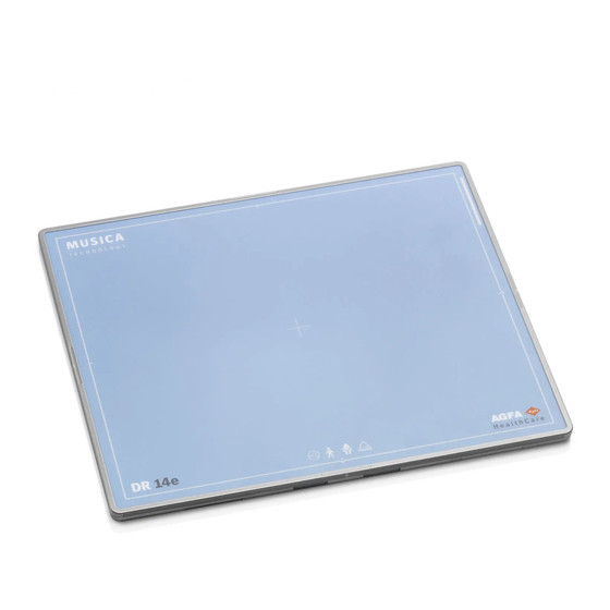
18 | DR 10e, DR 14e, DR 17e | Introduction to the DR Detector DR 10e, DR 14e, DR 17e Effective imaging area border and center position indication DR Detector battery lock lever DR Detector battery Battery status indicator DR Detector status indicators... - Page 19 DR 10e, DR 14e, DR 17e | Introduction to the DR Detector | 19 Antenna of the wireless network adapter Figure 4: DR Detector operation controls Ready indicator Power indicator Error indicator Link indicator Figure 5: DR Detector status indicators...
-
Page 20: Dr Detector Battery Charger
20 | DR 10e, DR 14e, DR 17e | Introduction to the DR Detector DR Detector Battery Charger The battery charger has two slots to insert a battery. Battery status indicator light Figure 6: DR Detector Battery Charger Related Links... -
Page 21: Dr Detector Switch On The Nx Workstation
DR 10e, DR 14e, DR 17e | Introduction to the DR Detector | 21 DR Detector Switch on the NX Workstation The DR Detector Switch is available in the title bar of the NX application. The DR Detector Switch shows which DR Detector is active and shows its status. - Page 22 22 | DR 10e, DR 14e, DR 17e | Introduction to the DR Detector Meaning DR Detec- DR Detector is DR Detector is DR Detector is tor is ready initializing for off or discon- inactive (no for expo- exposure nected or in...
-
Page 23: Wireless Access Point
DR 10e, DR 14e, DR 17e | Introduction to the DR Detector | 23 Wireless Access Point This antenna equipment relays captured images from the DR Detector to the NX workstation. Related Links Non-medical equipment on page 14 0370C EN 20200228 1449... -
Page 24: Dr Detector Connector Cable And Power Box
24 | DR 10e, DR 14e, DR 17e | Introduction to the DR Detector DR Detector connector cable and power box The DR Detector connector cable and power box are part of the wired configuration. The DR Detector connector cable connects the DR Detector to the DR Detector power box. - Page 25 DR 10e, DR 14e, DR 17e | Introduction to the DR Detector | 25 Hold the connector straight and not at an angle, to prevent damage. Make sure that the latches on both sides of the connector are properly engaged when connecting the connector. If the connector is not inserted completely, the power may turn off.
- Page 26 26 | DR 10e, DR 14e, DR 17e | Introduction to the DR Detector Make sure that the connector does not protrude from the edge of a bed. Do not place the connector on a hard surface such as the edge of a bed.
-
Page 27: Dr Detector Registration Cable
DR 10e, DR 14e, DR 17e | Introduction to the DR Detector | 27 DR Detector registration cable The DR Detector registration cable is part of the wireless configuration and required for initial setup and for sharing the DR Detector between NX workstations. -
Page 28: System Documentation
28 | DR 10e, DR 14e, DR 17e | Introduction to the DR Detector System Documentation The documentation consists of a User manual (this document) and related documentation: • NX User Manual (4420). • NX Key User Manual (4421). • NX Getting Started Sheets (4424). -
Page 29: Training
DR 10e, DR 14e, DR 17e | Introduction to the DR Detector | 29 Training The user must have received adequate training on the safe and effective use of the system before attempting to work with it. Training requirements may vary from country to country. -
Page 30: Product Complaints
30 | DR 10e, DR 14e, DR 17e | Introduction to the DR Detector Product Complaints Any health care professional (for example a customer or a user) who has any complaints or has experienced any dissatisfaction with the quality, durability, reliability, safety, effectiveness, or performance of this product must notify Agfa. -
Page 31: Compatibility
DR 10e, DR 14e, DR 17e | Introduction to the DR Detector | 31 Compatibility The system must only be used in combination with other equipment or components if these are expressly recognized by Agfa as compatible. A list of such equipment and components is available from Agfa service on request. -
Page 32: Compliance
32 | DR 10e, DR 14e, DR 17e | Introduction to the DR Detector Compliance Topics: • General • Safety • Electromagnetic Compatibility 0370C EN 20200228 1449... -
Page 33: General
DR 10e, DR 14e, DR 17e | Introduction to the DR Detector | 33 General • The product has been designed in accordance with the MEDDEV Guidelines relating to the application of Medical Devices and have been tested as part of the conformity assessment procedures required by 93/42/EEC Medical Device Directive (European Council Directive 93/42/EEC on Medical Devices). -
Page 34: Connectivity
34 | DR 10e, DR 14e, DR 17e | Introduction to the DR Detector Connectivity Topics: • Wireless Communication • Wired communication 0370C EN 20200228 1449... -
Page 35: Wireless Communication
DR 10e, DR 14e, DR 17e | Introduction to the DR Detector | 35 Wireless Communication Wireless communication is established between the internal wireless module of the DR Detector and the NX workstation via the wireless access point. The DR Detector is compliant with IEEE 802.11n (2.4 GHz/5 GHz). The available frequency band varies depending on local radio laws and system requirements. -
Page 36: Wired Communication
36 | DR 10e, DR 14e, DR 17e | Introduction to the DR Detector Wired communication The use of accessories and cables other than those specified or sold by the manufacturer as replacement parts, may result in increased radiation emissions or decreased stability of the equipment. -
Page 37: Installation
DR 10e, DR 14e, DR 17e | Introduction to the DR Detector | 37 Installation Installation and configuration is performed by an Agfa trained and authorized service engineer. Contact your local support organization for more information. On a configuration with multiple DR Detectors of the same type, it is required to apply labeling to the DR Detector containing a unique nickname for each DR Detector. - Page 38 38 | DR 10e, DR 14e, DR 17e | Introduction to the DR Detector Note: This product may malfunction due to electromagnetic waves caused by portable personal telephones, transceivers, radio- controlled toys, etc. Be sure to avoid having objects such as these, which affect this product, brought near the product.
-
Page 39: Messages
DR 10e, DR 14e, DR 17e | Introduction to the DR Detector | 39 Messages Under certain conditions the DR Detector shows a dialog box containing a message in the middle of the screen of the NX workstation. This message informs the user that either a problem has occurred or that a requested action cannot be performed. -
Page 40: Labels
40 | DR 10e, DR 14e, DR 17e | Introduction to the DR Detector Labels Symbol Explanation Tube side Direct current Alternating current Protective earth (ground) This mark indicates that this is a Type B Equipment Handle with care Caution for local load. Do not drop the detector on the user or on the patient. - Page 41 DR 10e, DR 14e, DR 17e | Introduction to the DR Detector | 41 Symbol Explanation Serial number This mark shows compliance of the equipment with Di- rective 93/42/EEC (for European Union). CE non harmonized frequency marking Indicates the autorized representative in the European...
- Page 42 42 | DR 10e, DR 14e, DR 17e | Introduction to the DR Detector • Additional Labeling of the DR Detector battery • Additional Labeling of the DR Detector battery charger • Additional Labeling of the DR Detector power box •...
-
Page 43: Additional Labeling Of The Dr Detector
DR 10e, DR 14e, DR 17e | Introduction to the DR Detector | 43 Additional Labeling of the DR Detector Type label on the back side of the DR Detector. Figure 11: Example of type label Access the label by remov- ing the battery. -
Page 44: Additional Labeling Of The Dr Detector Battery
44 | DR 10e, DR 14e, DR 17e | Introduction to the DR Detector Additional Labeling of the DR Detector battery Type label on the back side of the battery. Figure 13: Example of type label 0370C EN 20200228 1449... -
Page 45: Additional Labeling Of The Dr Detector Battery Charger
DR 10e, DR 14e, DR 17e | Introduction to the DR Detector | 45 Additional Labeling of the DR Detector battery charger Type label on the bottom side of the battery charger. Figure 14: Example of type label 0370C EN 20200228 1449... -
Page 46: Additional Labeling Of The Dr Detector Power Box
46 | DR 10e, DR 14e, DR 17e | Introduction to the DR Detector Additional Labeling of the DR Detector power box Type label on the back side of the power box. Figure 15: Example of type label 0370C EN 20200228 1449... -
Page 47: Consulting The About Box
DR 10e, DR 14e, DR 17e | Introduction to the DR Detector | 47 Consulting the About box 1. Click About the solution in the Tools section of the Main Menu window on the NX workstation. Figure 16: Main Menu window. -
Page 48: Cleaning And Disinfecting
48 | DR 10e, DR 14e, DR 17e | Introduction to the DR Detector Cleaning and Disinfecting All appropriate policies and procedures should be followed to avoid contamination of the staff, patients and equipment. All existing universal precautions should be extended to avoid potential contaminations and to avoid patients coming into (close) contact with the device. -
Page 49: Cleaning
DR 10e, DR 14e, DR 17e | Introduction to the DR Detector | 49 Cleaning To clean the exterior of the equipment: 1. Stop the system WARNING: When the equipment is going to be cleaned, be sure to turn OFF the power of each device, and to unplug the power cord from the AC outlet. -
Page 50: Use Of Protective Plastic Bag
50 | DR 10e, DR 14e, DR 17e | Introduction to the DR Detector Use of protective plastic bag WARNING: Liquids ingressing the DR Detector may cause malfunction and contamination. If there is a chance that the detector comes in contact with liquids (bodily fluids, disinfectants,...), the DR Detector must be wrapped in a protective... -
Page 51: Disinfecting
DR 10e, DR 14e, DR 17e | Introduction to the DR Detector | 51 Disinfecting WARNING: To disinfect the device, use only disinfectants and disinfection methods that are approved by Agfa and that correspond to the national regulation and guidelines as well as explosion protection. -
Page 52: Approved Disinfectants
52 | DR 10e, DR 14e, DR 17e | Introduction to the DR Detector Approved disinfectants Refer to the Agfa website for specifications on the disinfectants that have been found compatible with the cover material of the device and can be used on the outer surface of the device. -
Page 53: Safety Directions For Disinfection
DR 10e, DR 14e, DR 17e | Introduction to the DR Detector | 53 Safety directions for disinfection WARNING: When the equipment is going to be cleaned, be sure to turn OFF the power of each device, and to unplug the power cord from the AC outlet. -
Page 54: Maintenance
54 | DR 10e, DR 14e, DR 17e | Introduction to the DR Detector Maintenance Always consult the Agfa Service documentation and an Agfa trained and authorized service engineer for complete maintenance schedules. In order to ensure that the equipment is used safely and normally, be sure to inspect the equipment before use. -
Page 55: Yearly Inspection
DR 10e, DR 14e, DR 17e | Introduction to the DR Detector | 55 Yearly inspection To indicate when the yearly calibration is due, a message is displayed on the NX workstation. Perform calibration yearly or when exposure conditions have changed significantly. -
Page 56: Regular Inspection And Maintenance
56 | DR 10e, DR 14e, DR 17e | Introduction to the DR Detector Regular Inspection and Maintenance In order to ensure the safety of patients, operating personnel and third parties, and to maintain the performance and reliability of the equipment, be sure to perform regular inspection at least once a year. -
Page 57: Replacement Parts Support
DR 10e, DR 14e, DR 17e | Introduction to the DR Detector | 57 Replacement Parts Support Parts required to maintain the functioning of the product will be stocked for seven years after discontinuance of production, to allow for repair. -
Page 58: Repair
58 | DR 10e, DR 14e, DR 17e | Introduction to the DR Detector Repair The product can only be repaired in the factory. 0370C EN 20200228 1449... -
Page 59: Patient Data Security
DR 10e, DR 14e, DR 17e | Introduction to the DR Detector | 59 Patient data security The user must ensure that the patients’ legal requirements are met and that the security of the patient data is guarded. The user must define who can access patient data in which situations. -
Page 60: Environmental Protection
60 | DR 10e, DR 14e, DR 17e | Introduction to the DR Detector Environmental Protection Disposal of this product in an unlawful manner may have a negative impact on health and on the environment. Therefore, when disposing of this product, be absolutely sure to follow the procedure which is in conformity with the laws and regulations applicable in your area. - Page 61 DR 10e, DR 14e, DR 17e | Introduction to the DR Detector | 61 concentrations > 0.1 wt% in flat panel sensor. For details on product disposal, contact your local Agfa service organization and/or Agfa dealer. 0370C EN 20200228 1449...
-
Page 62: Safety Directions
62 | DR 10e, DR 14e, DR 17e | Introduction to the DR Detector Safety Directions WARNING: Safety is only guaranteed when an Agfa certified field service engineer has installed the product. WARNING: Improper changes, additions, maintenance or repair of the system can lead to personal injury, electrical shock and damage to the equipment. - Page 63 DR 10e, DR 14e, DR 17e | Introduction to the DR Detector | 63 WARNING: Do not hit or drop the equipment. The equipment may be damaged if it receives a strong jolt, which may result in fire or electric shock if the equipment is used without being repaired.
- Page 64 64 | DR 10e, DR 14e, DR 17e | Introduction to the DR Detector CAUTION: Handle the equipment carefully. Do not submerge the equipment in water. The internal image sensor may be damaged if something hits against it, or if it is dropped, or receives a strong jolt.
- Page 65 DR 10e, DR 14e, DR 17e | Introduction to the DR Detector | 65 CAUTION: Although the DR Detector conforms to IPX3, no warranty is given as to the prevention of water intrusion in the DR Detector. If the DR Detector is splashed with water, wipe off moisture. Be sure that all surfaces are thoroughly dry before returning the equipment to use.
-
Page 66: Safety Directions For The Dr Detector Battery
66 | DR 10e, DR 14e, DR 17e | Introduction to the DR Detector Safety Directions for the DR Detector battery CAUTION: To recharge the battery, use the battery charger specifically designed for the purpose and observe the recharging conditions specified by Agfa. A recharging operation under... - Page 67 DR 10e, DR 14e, DR 17e | Introduction to the DR Detector | 67 Recharge the stored battery pack every six months or every year. Otherwise a decrease in battery capacity or other problems may result. Do not use or subject the battery to intense sunlight or hot temperatures such as in a car in hot weather.
- Page 68 68 | DR 10e, DR 14e, DR 17e | Introduction to the DR Detector Do not strike or throw the battery. The impact might cause leakage, overheating, smoke emission, bursting and/or ignition. Also, if the protective feature in it becomes damaged, it could...
- Page 69 DR 10e, DR 14e, DR 17e | Introduction to the DR Detector | 69 during use, recharging or storage, immediately remove it from the equipment or battery charger and stop using it. Otherwise, the problematic battery can develop electrolyte leakage, overheating, smoke emission, bursting and/or ignition.
-
Page 70: Safety Directions For The Dr Detector Power Box
70 | DR 10e, DR 14e, DR 17e | Introduction to the DR Detector Safety Directions for the DR Detector power box WARNING: Do not touch the patient’s body while touching the image processing unit. Otherwise, the patient may receive an electric shock. -
Page 71: Safety Directions For The Power Supply
DR 10e, DR 14e, DR 17e | Introduction to the DR Detector | 71 Safety directions for the power supply WARNING: Do not operate the equipment using any type of power supply other than the one indicated on the rating label. Otherwise, it may result in fire or electric shock. - Page 72 72 | DR 10e, DR 14e, DR 17e | Introduction to the DR Detector WARNING: Be sure to hold the plug or connector to unplug the power cord. If you pull the power cord, the core wire may be damaged, resulting in fire or electric shock.
-
Page 73: Getting Started
DR 10e, DR 14e, DR 17e | Getting started | 73 Getting started Topics: • Starting the DR Detector (wireless configuration) • Starting the DR Detector (wired configuration) • Basic Workflow DR Detector • Guidelines for Pediatric Applications • Stopping the DR Detector (wireless configuration) •... -
Page 74: Starting The Dr Detector (Wireless Configuration)
CAUTION: Do not use the battery pack as a power source for equipment other than DR 10e, DR 14e or DR 17e detectors. Be sure to use only the dedicated battery pack for the DR 10e, DR 14e or DR 17e detector. - Page 75 DR 10e, DR 14e, DR 17e | Getting started | 75 c) Grip the lock lever to pull out the cover plate. 3. Attach the battery. Align the battery according to the guide marks. Insert the battery fully. Push down the battery.
- Page 76 76 | DR 10e, DR 14e, DR 17e | Getting started Detector Status Indicators on page 100 Registering the DR Detector on another NX Workstation on page 107 Problem solving on page 110 0370C EN 20200228 1449...
-
Page 77: Starting The Dr Detector (Wired Configuration)
DR 10e, DR 14e, DR 17e | Getting started | 77 Starting the DR Detector (wired configuration) Note: Before operating the detector, start up the NX workstation. To start the DR Detector: 1. Atach the cover plate of the battery bay if no battery is attached. -
Page 78: Basic Workflow Dr Detector
78 | DR 10e, DR 14e, DR 17e | Getting started Basic Workflow DR Detector Topics: • Step 1: retrieve the patient info • Step 2: select the exposure • Step 3: prepare the exposure • Step 4: check the exposure settings •... -
Page 79: Step 1: Retrieve The Patient Info
DR 10e, DR 14e, DR 17e | Getting started | 79 Step 1: retrieve the patient info At the NX workstation: 1. When a new patient comes in, define the patient info for the exam. 2. Start the exam. Step 2: select the exposure 1. -
Page 80: Step 3: Prepare The Exposure
80 | DR 10e, DR 14e, DR 17e | Getting started Step 3: prepare the exposure In the examination room: 1. Position the DR Detector. When using the bucky, check that the identification labels on the DR Detector and on the bucky match. Do not use a DR Detector that is dedicated to another bucky. -
Page 81: Step 4: Check The Exposure Settings
DR 10e, DR 14e, DR 17e | Getting started | 81 Step 4: check the exposure settings On the DR Detector Switch: 1. Check if the DR Detector Switch displays the name of the DR Detector that's being used 2. If a wrong DR Detector is displayed, select the right DR Detector by clicking the drop down arrow on the DR Detector Switch. -
Page 82: Step 5: Execute The Exposure
82 | DR 10e, DR 14e, DR 17e | Getting started Step 5: execute the exposure Press the exposure button to execute the exposure. Make sure the generator is ready for exposure before you press the exposure button. WARNING: The radiation indicator on the control console lights up during exposure release. -
Page 83: Positioning The Dr 10E
DR 10e, DR 14e, DR 17e | Getting started | 83 Positioning the DR 10e When performing an exposure, keep in mind the following detector orientation aids: • tube side • patient orientation marker Figure 22: Detector orientation aids 1. Tube side of the detector 2. - Page 84 84 | DR 10e, DR 14e, DR 17e | Getting started Note: NX is configured for a specific patient orientation, either head left (default) or head right. Note: Depending on the design of the bucky, the wired configuration may not support the use of the DR Detector in the bucky.
-
Page 85: Positioning The Dr 14E
DR 10e, DR 14e, DR 17e | Getting started | 85 Positioning the DR 14e When performing an exposure, keep in mind the following detector orientation aids: • tube side • patient orientation marker Figure 23: Detector orientation aids 1. Tube side of the detector 2. - Page 86 86 | DR 10e, DR 14e, DR 17e | Getting started 1. Detector orientation (Portrait) 2. Patient orientation (AP) 3. Result on monitor Table 3: Chest PA Landscape Figure 25: Chest PA landscape 1. Detector orientation (Landscape) 2. Patient orientation (PA) 3.
- Page 87 DR 10e, DR 14e, DR 17e | Getting started | 87 Table 5: Wallstand bucky Wallstand with left loading bucky, por- trait Wallstand with left loading bucky, land- scape Wallstand with right loading bucky, por- trait Wallstand with right loading bucky, land-...
-
Page 88: Positioning The Dr 17E
88 | DR 10e, DR 14e, DR 17e | Getting started Positioning the DR 17e When performing an exposure, keep in mind the following detector orientation aids: • tube side • patient orientation marker Figure 26: Detector orientation aids 1. Tube side of the detector 2. - Page 89 DR 10e, DR 14e, DR 17e | Getting started | 89 Note: NX is configured for a specific patient orientation, either head left (default) or head right. Table 7: Wallstand bucky Wallstand with left loading bucky Wallstand with right loading bucky...
-
Page 90: Guidelines For Pediatric Applications
90 | DR 10e, DR 14e, DR 17e | Getting started Guidelines for Pediatric Applications CAUTION: Children are more radiosensitive than adults. Adopting the Image Gently campaign guidelines and reducing dose for radiographic procedures while maintaining acceptable clinical image quality will benefit patients. - Page 91 DR 10e, DR 14e, DR 17e | Getting started | 91 • Avoid multiple scans and use alternative diagnostic studies (such as ultrasound or MRI) when possible. 0370C EN 20200228 1449...
-
Page 92: Stopping The Dr Detector (Wireless Configuration)
92 | DR 10e, DR 14e, DR 17e | Getting started Stopping the DR Detector (wireless configuration) WARNING: When the detector will not be used for some time, remove the battery. Otherwise, overdischarge may occur, leading to a shorter battery life. - Page 93 DR 10e, DR 14e, DR 17e | Getting started | 93 Align the cover plate according to the guide marks. Push down the cover plate. Figure 27: Attach the cover plate The cover plate is locked in position automatically. Note: When not in use, keep the detector, handle unit with grid in a designated location or in a location where they are safe and cannot fall down.
-
Page 94: Automatically Turning The Dr Detector To Sleep
94 | DR 10e, DR 14e, DR 17e | Getting started Automatically turning the DR Detector to sleep The DR Detector can be configured to switch to standby (sleep) automatically after not being used for a specific time. The power indicator and the battery status indicator remain on. -
Page 95: Stopping The Dr Detector (Wired Configuration)
DR 10e, DR 14e, DR 17e | Getting started | 95 Stopping the DR Detector (wired configuration) The DR Detector is connected to the DR Detector power box. No battery is attached to the DR Detector. To stop the DR Detector: 1. -
Page 96: Automatic Exposure Detection
96 | DR 10e, DR 14e, DR 17e | Getting started Automatic exposure detection The DR detector detects X-ray exposure to automatically perform the image acquisition. Before performing the exposure, the DR detector must be ready. Check the status of the DR detector in the DR Detector Switch. -
Page 97: Attaching The Handle Unit Without Grid
DR 10e, DR 14e, DR 17e | Getting started | 97 Attaching the Handle Unit without Grid To attach the handle unit for making exposures without using the grid 1. Lay down the handle unit on a flat surface. 2. Lay the DR Detector in the handle unit, bottom edge first, with the tube side facing up (1). -
Page 98: Attaching The Handle Unit With Grid
98 | DR 10e, DR 14e, DR 17e | Attaching the Handle Unit with Grid Attaching the Handle Unit with Grid CAUTION: To safely attach the handle unit for making exposures using the grid, follow these instructions. 1. Lay down the grid on a flat surface. -
Page 99: Advanced Operating
DR 10e, DR 14e, DR 17e | Advanced Operating | 99 Advanced Operating Topics: • Detector Status Indicators • Battery Status Indicator • Charging a battery • Storing a battery • Registering the DR Detector on another NX Workstation •... -
Page 100: Detector Status Indicators
100 | DR 10e, DR 14e, DR 17e | Advanced Operating Detector Status Indicators Table 8: DR Detector status Indicator Light Status Status X-ray generator Automatic expo- synchronization sure detection Not ready for exposure Ready status Green Status indicator During image trans-... -
Page 101: Battery Status Indicator
DR 10e, DR 14e, DR 17e | Advanced Operating | 101 Battery Status Indicator Table 9: Battery status during wireless operation (battery is discharging) Charging level of the battery Status indicator Available time: 60 minutes or more Available time: 20 minutes or more but less than... -
Page 102: Charging A Battery
102 | DR 10e, DR 14e, DR 17e | Advanced Operating Charging a battery To charge a battery using the battery charger: 1. Connect the power supply to the mains power and to the power socket of the battery charger. -
Page 103: Inserting The Battery In The Battery Charger
DR 10e, DR 14e, DR 17e | Advanced Operating | 103 Inserting the battery in the battery charger Insert the battery in the battery charger. Figure 28: Inserting the battery in the battery charger The battery charger produces a sound signal and the indicator lights light... -
Page 104: Battery Charger Indicator Lights
104 | DR 10e, DR 14e, DR 17e | Advanced Operating Battery charger indicator lights The battery charger has two slots to insert a battery. Each slot has a battery status display with indicator lights to inform the user about the status of the inserted battery. -
Page 105: First Use Of A New Battery
DR 10e, DR 14e, DR 17e | Advanced Operating | 105 First use of a new battery A new battery may need activation before using it in the DR Detector. 1. Insert the battery in the battery charger. The battery charger produces a sound signal and the indicator lights light 2. -
Page 106: Storing A Battery
106 | DR 10e, DR 14e, DR 17e | Advanced Operating Storing a battery Prolonged storage of a fully discharged or fully charged battery can damage the battery. Storage of a battery at elevated temperature can damage the battery. Batteries should be stored in a partially charged state, at storage temperature. -
Page 107: Registering The Dr Detector On Another Nx Workstation
DR 10e, DR 14e, DR 17e | Advanced Operating | 107 Registering the DR Detector on another NX Workstation The DR Detector can be used for examinations on different NX workstations. The DR Detector is set up to communicate to a specific NX workstation. The procedure of registering the DR Detector to another NX workstation switches the availability of the DR Detector between NX workstations. -
Page 108: Renewing The Eps License
108 | DR 10e, DR 14e, DR 17e | Advanced Operating Renewing the EPS license The EPS variant of the DR detector requires an active EPS license (Easy Payment Scheme). The EPS license is stored on the licensing dongle that is plugged into the NX workstation. - Page 109 DR 10e, DR 14e, DR 17e | Advanced Operating | 109 6. Start the DR detector again. The DR detector is now using the new license. 0370C EN 20200228 1449...
-
Page 110: Problem Solving
110 | DR 10e, DR 14e, DR 17e | Problem solving Problem solving Topics: • Artifact in DR Detector images • DR Detector status is not changing to ready for exposure • DR Detector is not switched to standby or switched off automatically •... -
Page 111: Artifact In Dr Detector Images
DR 10e, DR 14e, DR 17e | Problem solving | 111 Artifact in DR Detector images Details An artifact is visible in the images produced by a DR Detector. Cause Exposure conditions have changed significantly since latest calibration. Brief Solution Perform calibration of the DR Detector. -
Page 112: Dr Detector Is Not Switched To Standby Or Switched Off Automatically
112 | DR 10e, DR 14e, DR 17e | Problem solving DR Detector is not switched to standby or switched off automatically Details The DR detector is configured to switch to standby (sleep) or to switch off after not being used for a specific time, but it stays ac- tive. -
Page 113: A Program Is Preventing Windows From Logging Off
DR 10e, DR 14e, DR 17e | Problem solving | 113 A program is preventing Windows from logging off Details Log out of Windows. Windows is waiting for a program that is preventing Windows from logging off. Cause A program that is part of the DR Detector software is running when logging out of Windows. -
Page 114: Identifying Problems
114 | DR 10e, DR 14e, DR 17e | Problem solving Identifying problems Please refer to the details of following symptoms or error messages. If the problem persists, turn off the detector and consult your sales representative or local dealer. -
Page 115: Technical Data
DR 10e, DR 14e, DR 17e | Technical Data | 115 Technical Data Topics: • DR 10e, DR 14e, DR 17e • DR 10e, DR 14e, DR 17e Battery • DR 10e, DR 14e, DR 17e Battery Charger • DR 10e, DR 14e, DR 17e Power Box... -
Page 116: Dr 10E, Dr 14E, Dr 17E
116 | DR 10e, DR 14e, DR 17e | Technical Data DR 10e, DR 14e, DR 17e Electrical connection DR Detector Rated power supply 6–12V 2.73A DC (powered by battery pack) Rated power supply 100–240V 2–0.84A 50–60Hz AC (powered by power box) Wireless connection IEEE 802.11n (2.4 GHz/5 GHz) - Page 117 DR 10e, DR 14e, DR 17e | Technical Data | 117 Maximum load 120 kg on an area of 40 mm in diameter Vibration tolerance 0.03 mm p-p (10 - 57.5 Hz) 0.2 G (57.5 - 150 Hz) Shock tolerance...
-
Page 118: Dr 10E, Dr 14E, Dr 17E Battery
118 | DR 10e, DR 14e, DR 17e | Technical Data DR 10e, DR 14e, DR 17e Battery Type of product Rechargeable lithium ion battery pack Model 125N120009 2ICP/34/50-4 Dimensions Dimensions (length x 172.2 mm x 143.1 mm x 7.2 mm... -
Page 119: Dr 10E, Dr 14E, Dr 17E Battery Charger
DR 10e, DR 14e, DR 17e | Technical Data | 119 DR 10e, DR 14e, DR 17e Battery Charger Type of product Lithium ion battery pack charger Model 6011/105 Charging time 3 hours Simultaneous charging 2 batteries Water ingress IPX0 This device does not have protection against ingress of water. -
Page 120: Dr 10E, Dr 14E, Dr 17E Power Box
120 | DR 10e, DR 14e, DR 17e | Technical Data DR 10e, DR 14e, DR 17e Power Box Model 6011/107 Original model number PB-DRE-001 Dimensions Dimensions (width x height x depth) 259 mm x 70 mm x 205 mm 3.2 kg... -
Page 121: Remarks For Hf-Emission And Immunity
DR 10e, DR 14e, DR 17e | Remarks for HF-emission and immunity | 121 Remarks for HF-emission and immunity Topics: • EMC (Electromagnetic Compatibility) Statements • Precautions on EMC • Cables, transducers and accessories • Electromagnetic emissions • Electromagnetic immunity •... -
Page 122: Emc (Electromagnetic Compatibility) Statements
122 | DR 10e, DR 14e, DR 17e | Remarks for HF-emission and immunity EMC (Electromagnetic Compatibility) Statements The DR Detector is designed and tested to comply with IEC 60601-1-2(EN60601-1-2) which is applicable to regulations regarding EMC for medical devices and needs to be installed and put into service according to the EMC information stated as follows. -
Page 123: Precautions On Emc
DR 10e, DR 14e, DR 17e | Remarks for HF-emission and immunity | 123 Precautions on EMC Medical electrical equipment needs special precautions regarding EMC and needs to be installed and put into service according to the EMC information provided in the manual. - Page 124 124 | DR 10e, DR 14e, DR 17e | Remarks for HF-emission and immunity equipment may malfunction due to electromagnetic interference. WARNING: The emissions characteristics of this equipment make it suitable for use in industrial areas and residential environments and hospitals (CISPR 11 class B).
-
Page 125: Cables, Transducers And Accessories
DR 10e, DR 14e, DR 17e | Remarks for HF-emission and immunity | 125 Cables, transducers and accessories CAUTION: Using cables and accessories not mentioned in this manual or spare parts not ordered from Agfa, may cause a higher emission of electromagnetic phenomena and/or may rise the susceptibility against it. -
Page 126: Electromagnetic Emissions
126 | DR 10e, DR 14e, DR 17e | Remarks for HF-emission and immunity Electromagnetic emissions This DR Detector has been tested for the electromagnetic environment as described below. The user of the DR Detector should ensure that it is used in such an environment. -
Page 127: Electromagnetic Immunity
DR 10e, DR 14e, DR 17e | Remarks for HF-emission and immunity | 127 Electromagnetic immunity This DR Detector is intended for operation in the electromagnetic environment given below. The user of the DR Detector should ensure that it is used in such an environment. - Page 128 128 | DR 10e, DR 14e, DR 17e | Remarks for HF-emission and immunity Magnetic field at 30 A/m 30 A/m Power frequency the supply fre- magnetic fields quency (50/60 should be at levels characteristic of a typical location in a...
- Page 129 DR 10e, DR 14e, DR 17e | Remarks for HF-emission and immunity | 129 the transmitter in watts (W) ac- cording to the transmitter man- ufacturer and ’d’ is the recommen- ded separation distance in me- ters (m). Field strengths...
- Page 130 130 | DR 10e, DR 14e, DR 17e | Remarks for HF-emission and immunity Table 12: Test compliance levels between portable and mobile RF communications equipment and the DR detector ISM (Industrial, Scientific and Medical) frequency band compliance lev- Frequency...
-
Page 131: Recommended Separation Distance
DR 10e, DR 14e, DR 17e | Remarks for HF-emission and immunity | 131 Recommended separation distance This device is intended for operation in an electromagnetic environment in which the radiated high frequency disturbance variables are monitored. The user of the device can help to prevent electromagnetic disruptions by... -
Page 132: For U.s.a. And Canada
132 | DR 10e, DR 14e, DR 17e | Remarks for HF-emission and immunity For U.S.A. and Canada This device complies with Part 15 of FCC Rules and Industry Canada’s licence- exempt RSSs. Operation is subject to the following two conditions: (1) this device may not cause harmful interference, and (2) this device must accept any interference received, including interference that may cause undesired operation. - Page 133 DR 10e, DR 14e, DR 17e | Remarks for HF-emission and immunity | 133 down through the MAC, through the digital and analog baseband, and finally to the RF chip. Several special packets are initiated by the MAC. These are the only ways the digital baseband portion will turn on the RF transmitter, which it then turns off at the end of the packet.