Ariens Sno-Thro Professional Series Service Manual
Hide thumbs
Also See for Sno-Thro Professional Series:
- Service manual (84 pages) ,
- Operator's manual (34 pages) ,
- Operator's manual (30 pages)

Related Manuals for Ariens Sno-Thro Professional Series


Summary of Contents for Ariens Sno-Thro Professional Series
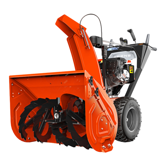
- Page 1 Service Manual ® Professional Series Sno-Thro Models 926076 – Professional 32 (SN 005000 +) 926077 – Professional 28 (SN 005000 +) 926339– Professional 28 CE (SN 005000 +) ENGLISH 05136230 • 11/19...
-
Page 2: Table Of Contents
TABLE OF CONTENTS PRACTICES & LAWS ......2 AUGER GEARCASE REPLACEMENT... . . 29 Remove Gearcase Assembly . - Page 3 A parts manual and an operator’s manual for your unit are available for free download or purchase at www.ariens.com. AriensCo recommends using only genuine Ariens replacement parts on this unit. Using unauthorized parts may adversely affect the performance, durability or safety of this unit and may void the warranty.
-
Page 4: Practices & Laws
Emission controls and 2. Warning components can only be adjusted by an Ariens dealer or an WARNING: Indicates a POTENTIALLY authorized engine manufacturer's service center. Contact HAZARDOUS SITUATION! If not avoided, your Ariens Retailer concerning emission controls and COULD RESULT in death or serious injury. -
Page 5: Safety Decals
SAFETY DECALS Stop engine, remove key, and read manual The safety decals on your machine are visual reminders of before making any repairs or adjustments. the important safety information in this manual. All messages on your unit must be fully understood and carefully followed. -
Page 6: Safety Rules
SAFETY RULES Handle fuel with care; it is highly flammable. • Use an approved fuel container. The following safety instructions are based on the B71.3 specifications of the American National Standards Institute • Never add fuel to a running engine or hot engine. in effect at the time of production. - Page 7 After striking a foreign object, stop the engine, remove the Never operate the snow thrower without good visibility or wire from the spark plug, disconnect the cord on electric light. Always be sure of your footing, and keep a firm hold motors, thoroughly inspect the snow thrower for any on the handles.
- Page 8 Maintain or replace safety and instruction labels as When practical, remove gas-powered equipment from the necessary. truck or trailer and refuel it on the ground. If this is not possible, then refuel on a trailer with a portable container, Run the machine a few minutes after throwing snow to rather than from a gasoline dispenser nozzle.
-
Page 9: Draining Fuel System
DRAINING FUEL SYSTEM SEPARATE HOUSING FROM FRAME Remove Auger Housing Move unit to an open, well-ventilated area with no flames or sparks. IMPORTANT: Save all hardware for reinstallation. Remove fuel tank cap and siphon fuel into a clean Stop engine, remove key and wait for moving parts to gasoline container. - Page 10 See Figure 4. See Figure 5. Remove hairpin from clevis pin and partially remove 10. Remove hairpin, sleeve bushing and cable eyelet from clevis pin from chute control assembly. deflector arm under control panel. Using pliers, compress cable anchor tabs and remove 11.
- Page 11 12. Remove chute deflector cable from J-clamp on engine 15. Remove hardware retaining belt finger to engine and mount. See Figure 6. remove belt finger. See Figure 8. Figure 6 See Figure 7. Figure 8 13. Fully loosen tapping screw securing left side of belt cover to frame.
- Page 12 See Figure 9. See Figure 11. 16. Remove attachment drive belts from attachment 19. Remove hardware securing auger housing to frame. sheave. 20. Lift auger housing rear slightly to disengage from To assist belt removal, slowly pull recoil starter handle mount rod and separate from unit.
-
Page 13: Reinstall Auger Housing
Reinstall Auger Housing See Figure 13. See Figure 12. WARNING: AVOID INJURY. Attachment sheave With help from a capable assistant, engage edges are sharp. Wear thick gloves to install attachment clutch lever so attachment brake will not belts onto attachment sheave. obstruct attachment drive pulley in step 2. - Page 14 See Figure 14. See Figure 15. 10. Check belt finger clearance: 17. Remove hairpin from clevis pin, partially remove clevis pin from chute control assembly and reinstall cable • Engage attachment clutch lever and ensure belt eyelet onto clevis pin. finger located opposite belt idler is less than 3.2 mm (1/8") from belt, but not touching the belt.
-
Page 15: Bottom Cover Removal
BOTTOM COVER REMOVAL ATTACHMENT DRIVE BELT REPLACEMENT Remove Bottom Cover Remove Attachment Drive Belts IMPORTANT: Save all hardware for reinstallation. IMPORTANT: Save all hardware for reinstallation. WARNING: AVOID INJURY. Before placing unit Stop engine, remove key and wait for all moving parts in service position, drain fuel from tank and fuel to stop and for hot parts to cool. -
Page 16: Traction Drive Belt Replacement
TRACTION DRIVE BELT See Figure 19. Rotate traction idler arm away from belt and rotate REPLACEMENT swing gate assembly forward. Remove Traction Drive Belt Remove belt. IMPORTANT: Save all hardware for reinstallation. Stop engine, remove key and wait for all moving parts to stop and for hot parts to cool. -
Page 17: Install Traction Drive Belt
Install Traction Drive Belt DRIVE IDLER ASSEMBLY REPLACEMENT See Figure 20. Install belt onto traction sheave and traction drive Remove Attachment Drive Idler Assembly pulley. IMPORTANT: Save all hardware for reinstallation. Return swing gate assembly into upright position and Stop engine, remove key and wait for all moving parts thread stop bolt fully back into tractor frame. -
Page 18: Remove Traction Drive Idler Assembly
See Figure 22. See Figure 23. Disconnect torsion spring from attachment idler arm. Disconnect tension spring from traction drive idler arm. Remove tapping screws retaining attachment idler arm to hub and remove idler assembly. Remove roll pin and attachment idler arm hub from drive idler pivot rod. -
Page 19: Install Traction Drive Idler Assembly
Install Traction Drive Idler Assembly See Figure 26. Align attachment arm idler hub with hole through pivot See Figure 25. rod and reinstall roll pin. If removed, reinstall traction drive belt. Reinstall idler spring onto traction drive idler arm and Reinstall traction drive idler assembly and torsion ensure traction drive belt is aligned in all pulleys. -
Page 20: Install Attachment Drive Idler Assembly
Install Attachment Drive Idler Assembly Reinstall attachment brake spring onto attachment brake arm and frame. See Figure 28. See Figure 27. IMPORTANT: Push attachment brake arm down as idler assembly is reinstalled. Secure attachment idler arm to hub with original tapping screws. -
Page 21: Attachment Brake Replacement
ATTACHMENT BRAKE REPLACEMENT Remove hardware retaining attachment brake arm to brake mount bracket and remove attachment brake Remove Attachment Brake arm. See Figure 30. IMPORTANT: Save all hardware for reinstallation. Stop engine, remove key and wait for all moving parts to stop and for hot parts to cool. -
Page 22: Install Attachment Brake
Install Attachment Brake Attachment Clutch Engaged / Brake Disengaged Position pivoting end of attachment brake arm in brake mount bracket. Secure with hex bolt and top locking flange nut. DO NOT overtighten. IMPORTANT: Brake arm MUST rotate freely after hardware has been tightened. With flathead screwdriver or similar pry bar, reconnect extension spring to attachment brake arm and tractor frame. -
Page 23: Friction Disc Replacement
FRICTION DISC REPLACEMENT See Figure 33. Check attachment brake: Remove Friction Disc • When attachment clutch is disengaged, brake must IMPORTANT: Save all hardware for reinstallation. contact attachment belt or pulley, whichever is closest. WARNING: AVOID INJURY. Before placing unit •... -
Page 24: Install Friction Disc
Install Friction Disc See Figure 35. Remove two spring clips from hex shaft. Align friction disc assembly with shift fork roller bearing and hex shaft. See Figure 37. Remove hardware securing bearing to left side of frame and remove bearing flange. Remove bearing from hex shaft end. -
Page 25: Swing Gate Replacement
SWING GATE REPLACEMENT See Figure 39. Reinstall bearing onto hex shaft end. Remove Swing Gate Reinstall bearing flange over bearing and secure to NOTICE: Save all hardware for reinstallation. frame with three tapping screws. Stop engine, remove key and wait for all moving parts Reinstall spring clips into hex shaft. - Page 26 Remove belt cover. See Figure 7. Place unit in service position. See Service Position on page 7. Disconnect traction drive idler spring. See Figure 41. Remove bottom cover. See Bottom Cover Removal on page 13. 10. Remove snap clip from right-side axle end and remove wheel and axle key.
-
Page 27: Install Swing Gate Assembly
Install Swing Gate Assembly 12. Remove two hair pins retaining swing gate assembly to swing gate pivot pin and remove pin. See Figure 45. WARNING: AVOID INJURY. Wear thick gloves; traction drive pulley and engine sheave edges are sharp. Position swing gate assembly inside frame. Reinstall traction drive belt on traction drive pulley. -
Page 28: Auger Replacement
AUGER REPLACEMENT Secure swing gate assembly to pivot rod with two hairpins inserted curved side up at 90-degree angles Remove Auger to the gate. See Figure 48. IMPORTANT: Save all hardware for reinstallation. Stop engine, remove key and wait for all moving parts to stop and for hot parts to cool. - Page 29 Remove hardware retaining support bushings to auger See Figure 52. housing. See Figure 50. IMPORTANT: Flange bushing remains inside support bushing. Remove support bushing from auger shaft end. Remove shear bolt from auger shaft. 10. Remove auger. Use of penetrating oil or heat may be necessary to remove auger.
-
Page 30: Install Auger
Install Auger Reinstall auger assembly into housing so impeller shaft is seated in ball bearing at housing rear. See See Figure 51. Figure 54. Install auger onto auger shaft with auger kickers facing gearcase. IMPORTANT: Ensure auger helix direction matches original auger orientation. -
Page 31: Auger Gearcase Replacement
AUGER GEARCASE REPLACEMENT See Figure 55. Tighten three hex nuts securing bearing plate to auger Remove Gearcase Assembly housing. IMPORTANT: Save all hardware for reinstallation. 10. Apply a thin layer of anti-seize compound to impeller Stop engine, remove key and wait for all moving parts shaft end. -
Page 32: Impeller Replacement
IMPELLER REPLACEMENT Install Impeller See Figure 58. Remove Impeller Apply a thin layer of anti-seize compound to impeller IMPORTANT: Save all hardware for reinstallation. shaft. Stop engine, remove key and wait for all moving parts Install impeller onto impeller shaft. to stop and for hot parts to cool. -
Page 33: Engine Replacement
ENGINE REPLACEMENT Secure support bushings to auger housing with six tapping screws. See Figure 60. Remove Engine IMPORTANT: Save all hardware for reinstallation. Stop engine, remove key and wait for all moving parts to stop and for hot parts to cool. Disconnect spark plug wire from engine. - Page 34 See Figure 63. See Figure 64. Remove chute deflector cable from J-clamp on engine 11. Remove hardware securing sheaves to crankshaft. mount. 12. Remove attachment and traction sheaves from Remove hardware securing engine mount to frame. crankshaft. Figure 64 Figure 63 WARNING: AVOID INJURY.
-
Page 35: Install Engine
Install Engine WARNING: AVOID INJURY. Attachment sheave edges are sharp. Wear thick gloves to install WARNING: AVOID INJURY. Engine is heavy. belts onto attachment sheave. NEVER lift engine without a suitable lifting device or capable assistant. Reinstall attachment drive belts.To assist belt installation, slowly pull recoil starter handle while Using a suitable lifting device or help from a capable gently guiding belt onto attachment sheave. -
Page 36: Traction Drive Clutch Cable Replacement
TRACTION DRIVE CLUTCH CABLE See Figure 68. Reinstall belt finger and secure with two flat steel REPLACEMENT washers, two locking washers and two hex bolts. Remove Traction Drive Clutch Cable Check belt finger clearance: IMPORTANT: Save all hardware for reinstallation. •... -
Page 37: Install Traction Drive Clutch Cable
Disconnect lower traction drive cable from upper Remove belt cover. See Figure 7. traction drive cable. See Figure 70. Remove lower traction clutch cable hook from swing gate. See Figure 72. Figure 70 Figure 72 Loosen, but DO NOT remove shoulder bolt retaining cable pulley to cable pulley bracket. - Page 38 See Figure 74. Route cable between cable pulley and bracket and tighten shoulder bolt. Reconnect lower traction clutch cable to upper traction clutch cable. Figure 73 Route cable to rear of unit and through access hole in tractor frame. Ensure that cable is routed above hex shaft 1.
-
Page 39: Dual-Handle Interlock Replacement
DUAL-HANDLE INTERLOCK IMPORTANT: Interlock cams will fall from camshafts in next step. REPLACEMENT Remove hardware retaining camshafts to clutch levers Remove Interlock Cam and remove camshafts from interlock bracket. See Figure 76. IMPORTANT: Save all hardware for reinstallation. See Figure 75. Disconnect spring from interlock bracket. -
Page 40: Axle Bearing Replacement
1. Sleeve Spacer 2. Flange Bearing 3. Axle Key 4. Bearing Plate Figure 80 Figure 79 Check dual-handle interlock function. Refer to Operator’s Manual for test procedure. IMPORTANT: If dual-handle interlock continues to malfunction, see your Ariens dealer. EN – 38... -
Page 41: Install Left Axle Bearing
Install Left Axle Bearing See Figure 82. IMPORTANT: Two flat steel washers will fall when short Install flange bearing onto axle and align with bearing axle is removed. plate. Support differential gear and remove sleeve spacer Insert three hex bolts from inside frame through and short axle. -
Page 42: Install Right Axle Bearing
Install Right Axle Bearing See Figure 85. Reinstall long axle into differential gear. Align bearing with bearing plate and position on frame with three hex bolts from inside frame. Retain with Reinstall E-ring onto axle end. three locking nuts. See Figure 84. Reinstall short axle until a small portion of axle is through frame. -
Page 43: Flange Bushing Replacement
FLANGE BUSHING REPLACEMENT See Figure 87. IMPORTANT: Sleeve bushing between pinion gear and Remove Flange Bushing frame will fall when pinion shaft is removed. IMPORTANT: Save all hardware for reinstallation. Remove pinion shaft from pinion gear. Remove pinion gear from chain. WARNING: AVOID INJURY. -
Page 44: Hex Shaft Bearing Replacement
HEX SHAFT BEARING REPLACEMENT See Figure 88. Center pinion shaft and position spacer on left side of Remove Hex Shaft Bearing shaft against frame. IMPORTANT: Save all hardware for reinstallation. Reinstall spring clip into pinion shaft. Stop engine, remove key and wait for all moving parts to stop and for hot parts to cool. -
Page 45: Differential Gear Replacement
DIFFERENTIAL GEAR REPLACEMENT See Figure 91. IMPORTANT: Two flat steel washers will fall when short Remove Differential Gear axle is removed. IMPORTANT: Save all hardware for reinstallation. Support differential gear and remove sleeve spacer and short axle. WARNING: AVOID INJURY. Before placing unit Remove differential gear and flat steel washers. -
Page 46: Chute Gear Replacement
CHUTE GEAR REPLACEMENT Remove Chute Rotation Gear IMPORTANT: Save all hardware for reinstallation Stop engine, remove key and wait for all moving parts to stop and for hot parts to cool. Disconnect spark plug wire from engine. See Figure 94. Position discharge chute facing forward. -
Page 47: Install Chute Rotation Gear
Install Chute Rotation Gear See Figure 95. IMPORTANT: Support discharge chute so it remains IMPORTANT: Ensure discharge chute is positioned facing upright. forward. Remove hardware securing chute rotation gear to See Figure 96. pedestal plate and remove chute gear. Position actuation gear so gear teeth are at lowest position. -
Page 48: Remove Actuation Gear
Remove Actuation Gear SCRAPER BLADE REPLACEMENT IMPORTANT: Save all hardware for reinstallation. Remove Scraper Blade Stop engine, remove key and wait for all moving parts IMPORTANT: Save all hardware for reinstallation. to stop and for hot parts to cool. Disconnect spark plug wire from engine. WARNING: AVOID INJURY. -
Page 49: Install Scraper Blade
HEADLIGHT REPLACEMENT See Figure 99. Slowly tip unit back so it rests on handlebars. Remove Bulb Remove remaining hardware securing scraper blade IMPORTANT: Save all hardware for reinstallation. to auger housing and remove scraper blade. Stop engine, remove key and wait for all moving parts to stop and for hot parts to cool. -
Page 50: Install Bulb
GEARCASE REBUILD Disassemble Gearcase IMPORTANT: Save all parts for reassembly, unless otherwise specified. Remove gearcase. See Remove Gearcase Assembly on page 29. Remove any rust, if present, from auger and impeller shafts with sandpaper. Wipe clean with oil. Remove drain plug and seal washer from gearcase. See Figure 103. - Page 51 See Figure 104. See Figure 106. Remove hardware retaining gearcase cover and Press auger shaft through the right side of gearcase. remove cover. NOTICE: DO NOT strike auger shaft end; use a suitable Remove gasket and drain gearcase. press. Remove seal, bushing and washer from auger shaft. Figure 104 Remove bushing retainer from gearcase.
- Page 52 10. Using snap ring pliers, remove retaining ring. See 14. Remove seals and flange bushings from gearcase. Figure 108. See Figure 110. Figure 108 Figure 110 See Figure 109. 11. Using a suitable bearing press tool, press impeller shaft end until shaft is through front of gearcase. NOTICE: DO NOT strike impeller shaft end.
-
Page 53: Assemble Gearcase
Assemble Gearcase See Figure 113. Reinstall impeller shaft through gearcase front and See Figure 111. reinstall thrust collar onto impeller shaft end. Press rear seal into gearcase until flush with gearcase Wrap a seal protector around impeller shaft end and exterior. - Page 54 See Figure 114. Reinstall flange bushing onto impeller shaft end. With a driver, strike bushing until positioned just below Reinstall pin into impeller shaft and turn shaft so pin is retaining ring groove. See Figure 115. horizontal. Align thrust collar with pin and install thrust collar over pin.
- Page 55 See Figure 117. 15. With a driver, such as a 1 1/4" deep-well socket, drive bushing into gearcase until groove is just beyond 12. Reinstall one flat steel washer into left side of interior gearcase wall. See Figure 119. gearcase. 13.
- Page 56 See Figure 121. (2.4" – 2.6") from the flat surface of the gearcase cover. IMPORTANT: Ariens recommends using only Ariens L3 synthetic sever duty gear lube. Using other lubricants will not automatically void unit warranty, but the warranty will not cover damage caused by using unauthorized lubricants.
- Page 57 SERVICE RECORD DATE SERVICE COMPLETED NOTES EN – 55...
- Page 58 655 West Ryan Street Brillion, WI 54110 www.ariensco.com parts.ariens.com...