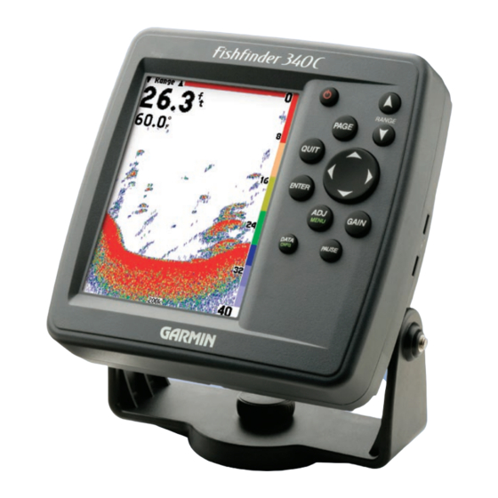
Garmin FishFinder 340C Owner's Manual
Color sonar
Hide thumbs
Also See for FishFinder 340C:
- Owner's manual (56 pages) ,
- Quick reference (2 pages) ,
- Declaration of conformity (1 page)
Table of Contents
Advertisement
Quick Links
Download this manual
See also:
Installation Manual
Advertisement
Table of Contents

Related Manuals for Garmin FishFinder 340C


Summary of Contents for Garmin FishFinder 340C
- Page 1 Fishfinder 340C full-featured color sonar owner’s manual...
- Page 2 Information in this document is subject to change without notice. Garmin reserves the right to change or improve its products and to make changes in the content without obligation to notify any person or organization of such changes or improvements. Visit the Garmin Web site (www.garmin.com) for current updates and supplemental information concerning the use and operation of this and other Garmin products.
-
Page 3: About This Manual
• CANet™ capability, which enables you to connect your unit to CANet-capable Garmin chartplotters, so you can read the Sonar Pages on chartplotters located elsewhere in the boat. • Round flasher, which gives you an option for how to view the sonar. -
Page 4: Product Registration
Serial Number: ___ ___ ___ ___ ___ ___ ___ ___ Contact Garmin If you encounter any difficulty while using your Fishfinder, or if you have any questions, in the U.S.A. contact Garmin Product Support by phone: 913/397.8200 or 800/800.1020, Monday– Friday, 8 AM–5 PM Central Time; or go to www.garmin.com/support/ and click on Product Support. -
Page 5: Table Of Contents
ABLE OF ONTENTS Introduction ...i About This Manual ... i Product Registration ... ii Contact Garmin ... ii Caring for the Fishfinder ... ii Warning ... iv Getting Started ...1 Packing List ... 1 Optional Accessories ... 1 Understanding the Fishfinder and Sonar ... 2 Installing the Fishfinder 340C ...5... -
Page 6: Warning
WARNING: This product, its packaging, and its components contain chemicals known to the State of California to cause cancer, birth defects, or reproductive harm. This Notice is being provided in accordance with California’s Proposition 65. If you have any questions or would like additional information, please refer to our Web site at http://www.garmin.com/prop65. Fishfinder 340C Owner’s Manual... -
Page 7: Getting Started
Before installing and using your Fishfinder 340C, check to see that your package includes the following items. The package number is on the outside of the box. If any parts are missing, contact your Garmin dealer immediately. Packing List Standard Package (010-00505-00) •... -
Page 8: Understanding The Fishfinder And Sonar
ETTING TARTED NDERSTANDING THE ISHFINDER AND Understanding the Fishfinder and Sonar The Fishfinder 340C is a fully automatic, color sonar unit that allows you to go out on the water and find fish without having to configure a lot of settings; or, if from experience you know exactly how you want your Fishfinder screen to look and function, you can customize each setting to your specific needs and wants. -
Page 9: Using Dual Beam
Using Dual Beam Dual beam works best for shallow water (for example, inland) applications. A dual beam transducer can transmit a narrow or a wide beam. The water area covered by the transmitted sound waves is determined by the beam width of the transducer and the water depth. - Page 10 ETTING TARTED NDERSTANDING THE ISHFINDER AND Water depth Bottom The strongest sonar returns appear on your screen as the most intense solid color (depending on your selected color scheme; red is the default). The weakest returns appear as the less intense, less solid colors (blue is the default).
-
Page 11: Installing The Fishfinder 340C
• Verify that all cables can reach the unit mounting location and the transducer. • Wear safety goggles and a dust mask when drilling, cutting, or sanding. If you experience difficulty installing the unit, contact Garmin Product Support or contact a professional installer. ELECTING A OCATION FOR THE... -
Page 12: Mounting The Fishfinder
NSTALLING THE ISHFINDER OUNTING THE Mounting the Fishfinder There are two possible installation methods for your Fishfinder: • You can mount the Fishfinder onto a bracket that attaches to the console or overhead. • You can flush mount the Fishfinder into a flat panel. Surface Mounting the Fishfinder The Fishfinder 340C’s compact, waterproof case is suitable for mounting in exposed locations or at the nav station. - Page 13 4. Place the swivel mount bracket over the swivel base and secure it with the short knob. Installing the Unit on the Mounting Bracket To install the Fishfinder on the mounting bracket: 1. Align the slot on the back of the Fishfinder with the long mounting knob, and slide the Fishfinder into place.
- Page 14 NSTALLING THE ISHFINDER OUNTING THE Included mounting hardware—(4) 3 mm studs, (4) flat washers, and (8) 3 mm hex nuts. Tools (not included)—center punch, drill, 1/8 (6 mm) drill bit, jig saw, 1/16 (2 mm) Allen wrench, and 9/32 " "...
-
Page 15: Mounting The Transducer
DO NOT cut the transducer lead or any part of the transducer cable, because this voids your warranty. The cable cannot be spliced and connected to any existing (Garmin or non-Garmin) transducer cables. Following are some tips and basic installation instructions for some popular transducers. - Page 16 NSTALLING THE ISHFINDER OUNTING THE Mounting the Transducer on a Trolling Motor (Dual Beam Only) To mount the transducer on a trolling motor: 1. Slide the large cable tie through the slot on the transducer mount (see the illustration on page 9) with the ridges of the band facing up until equal lengths extend on both sides of the mount.
- Page 17 Mounting the Transducer on a Transom When selecting a transom mount location, consider the following for optimal performance: • For your sonar to operate properly, the transducer must be located in calm water. DO NOT mount the transducer behind strakes, rivet lines, struts, fittings, water intake, discharge ports, eroding paint, or anything that creates turbulence.
- Page 18 NSTALLING THE ISHFINDER OUNTING THE Tool List (not included)—drill, 3/8" wrench or socket, 5/32" and 1/8" drill bits, masking tape, #2 Phillips screwdriver, and marine sealant. To mount the transducer on a transom: 1. Position the transducer mount at the selected transom location.
- Page 19 340C > NSTALLING THE ISHFINDER OUNTING THE RANSDUCER Shoot-Thru-Hull Installation Drill pilot holes here. To avoid drilling a hole to mount a thru-hull transducer, a Level transducer can be secured with epoxy inside a boat (shoot-thru- hull installation). This type of installation can provide better Align with the transom noise reduction and allow you to use a higher Gain setting.
- Page 20 NSTALLING THE ISHFINDER OUNTING THE Selecting a Location for a Shoot-Thru-Hull Installation When installing a transducer, the installation location must be the following: • Solid fiberglass, without any air bubbles, laminates, fillers, or dead air space. • In an area of clean (non-turbulent) water at all speeds. •...
-
Page 21: Installing The Wiring Harness
Installing the Wiring Harness The Fishfinder comes with a wiring harness that connects the Fishfinder to power and the transducer with one easy-to-remove connection and provides interface capabilities for connecting external devices. The color code in the diagram (see page 18) indicates the appropriate harness connections. - Page 22 1. Follow the voltage source installation steps (see page 15). For Garmin units, the ground (Black) wires serve as data ground and must be attached together or on the same terminal. Refer to the wiring diagram of your GPS unit for wire identification.
- Page 23 Output—SDDBT, SDDPT, SDMTW, SDVHW, SDWPL* (only if a waypoint is marked in Pointer mode). *Garmin GPS units accept an SDWPL (WPL) NMEA sentence and create a waypoint (saved location) at that position (page 41). For compatibility with other brands of GPS or NMEA capable navigation devices, check with those manufacturers to see if their units accept and store NMEA 0183 SDWPL sentences and waypoints.
- Page 24 340C > NSTALLING THE ISHFINDER NSTALLING THE IRING ARNESS (CANet L) Orange (Accessory On) (CANet H) (RX NMEA) (TX NMEA) DC Power Accessory On �������� Source CANet L CANet H Fishfinder 340C Owner’s Manual...
-
Page 25: Testing The Installation
Testing the Installation While it is possible to perform some checks with the boat trailered, the boat should be in the water to properly test the sonar portion of the installation. To test the installation: 1. Press and hold the Power/Backlight key until the Fishfinder beeps. - Page 26 340C > NSTALLING THE ISHFINDER ESTING THE NSTALLATION 4. If the signal does not improve, it might be necessary to move the transducer to a different location. NOTE: When adjusting the depth of the transducer, make the adjustments in small increments. Placing the transducer too deep can adversely affect the boat’s performance and put the transducer at greater risk of striking underwater objects.
-
Page 27: Using The Fishfinder 340C
SING THE ISHFINDER If you are turning on your Fishfinder 340C for the first time, use the following procedure. If you have already turned on your Fishfinder, and you are just familiarizing yourself with the basic functions, please go to “Learning the Basic Functions” on this page. To start your Fishfinder for the first time: 1. -
Page 28: Using Simulator Mode
340C > SING THE ISHFINDER SING IMULATOR Using Simulator Mode You can use Simulator mode to practice and learn the operation of the Fishfinder. If the Fishfinder does not detect a transducer at startup, it automatically starts in Simulator mode. While in Simulator mode, the Fishfinder displays a bottom scene, and you can control the Fishfinder (except the Gain and Auto Gain options). -
Page 29: Using The Fishfinder 340C Keypad
• Press to mark a waypoint at the pointer position when in Pointer mode (when connected to a compatible NMEA GPS. ADJ/MENU Key • Press to open the Adjustment Menu. • Press and hold to open the Main Menu. -
Page 30: Understanding The Main Pages
SING THE ISHFINDER NDERSTANDING THE Understanding the Main Pages The Fishfinder 340C typically offers several main pages for you to use, including the Sonar Page, Flasher Page, and Numbers Page. If you are using a dual frequency transducer, and you have the Frequency set to Dual, the following pages are available instead: Split Sonar (200 kHz and 50 kHz), Sonar (200 kHz), Sonar (50 kHz), and Numbers. - Page 31 If you are using a dual frequency transducer and you set the Frequency to Dual, you can access the Split Sonar Page, the Sonar (220kHz) Page, the Sonar (50kHz) Page, and its related Adjustment Menu. Split Sonar Page with Adjustment Menu For all Sonar Pages, the currently selected adjustment option (page 36) appears in the upper-left corner of the screen.
- Page 32 SING THE ISHFINDER NDERSTANDING THE To split the screen: 1. From a Sonar Page, press ADJ/MENU. The Adjustment Menu appears. 2. Use the Rocker to select Split When Zoomed, and press ENTER. 3. Use the Rocker again to select On, and press ENTER. The current page is now a split screen.
-
Page 33: Using The Main Menu
Using the Numbers Page When you use the Numbers Page, you can view three data fields of your choice. (See “Configuring Advanced Data Fields” on page 39 for more information about the data fields.) To change the data fields on the Numbers Page: 1. -
Page 34: Graph Tab
SING THE ISHFINDER SING THE 3. Use the Rocker to highlight the setting you want to change, and press ENTER. The available settings appear. 4. Use the Rocker to highlight the setting you want, and then press ENTER. The new setting is now active. Your changes to the Main Menu settings are used until you go to the Main Menu and set the System Factory Settings option to Yes. -
Page 35: Sonar Tab
• Scale—controls the depth scale displayed vertically along the right side of the graph. The settings are Overlay (default), in the Corners, Basic scale, or No Scale. • Custom Range—allows you to specify a custom viewing range or scale. When On, this range appears as Custom in the Range setting. - Page 36 1. Use the Rocker to highlight Calibrate Water Speed, and press ENTER. 2. Bring the boat to a cruising speed. Both the top GPS ground speed and uncalibrated water speed appears at the bottom of the calibration window. Note your top speed, then stop the boat, and press ENTER.
- Page 37 NOTE: If the boat is not moving fast enough or the speed sensor is not registering a speed, a “Boat Is Not Moving Fast Enough To Calibrate” message appears at the bottom of the screen. Check that the speed sensor wheel is moving or safely increase boat speed.
-
Page 38: Alarms Tab
SING THE ISHFINDER SING THE Alarms Tab The Alarms tab contains settings for the Fishfinder’s alarms. (For a list of alarms and unit messages, see page 45.) The Alarm tab is divided into two sub tabs: Sonar alarms and System alarms. To set an alarm: 1. -
Page 39: System Tab
System Sub Tab • Battery—sets an alarm to sound when the battery is reaching a critical state of discharge. The settings are Off (default) and a user-defined number of volts remaining. • Timer—allows you to control a timer. This can be useful for tournament fishing. -
Page 40: Units Tab
• NMEA Input/Output—controls the input and output of NMEA 0183 version 3.01 data to and from the Fishfinder. This setting must be On to receive GPS navigational data and send Sonar NMEA data. See page 17 for details on available NMEA sentences. -
Page 41: Time Tab
12 or 24-hour time format, enter a time zone, and adjust for daylight saving time to show correct local time. The time appears only if you are receiving valid NMEA input from a GPS unit (see page 17) or if the Fishfinder is in Simulator mode. -
Page 42: Using The Adjustment Menu
SING THE ISHFINDER SING THE DJUSTMENT Using the Adjustment Menu The Adjustment Menu gives you direct access to the most commonly used settings and features. The Adjustment Menu also provides a quick review of how the sonar is configured. This menu varies, depending on your transducer type, your current page, and your current settings. - Page 43 • Gain—controls the sensitivity of the Fishfinder’s sonar receiver. Auto (default) is the recommended setting. It automatically sets the sonar sensitivity. You can also set the gain manually. To see more detail on the screen, increase the receiver sensitivity by selecting a higher gain. If there is too much detail or if the screen is cluttered, lower the sensitivity (lower the gain) to increase the clarity of the screen.
- Page 44 SING THE ISHFINDER SING THE DJUSTMENT • Depth Line—adds a horizontal depth line across the screen that is used to measure the depth of underwater objects. The depth of the line appears on the right side of the line. Press up or down on the Rocker to control the position of the line on the Sonar Pages.
-
Page 45: Configuring Advanced Data Fields
Configuring Advanced Data Fields The top-left corner of the screen contains configurable data fields for the Sonar Pages. You can display basic or advanced data for these data fields. By default, the Basic configuration shows the depth, water temperature, and speed (depending on the Graph tab settings and the type of transducer or sensors attached). - Page 46 POINTER—an arrow that points toward a destination waypoint from your current position (BRG). This field requires NMEA input. SOG (speed over ground)—the actual speed that the GPS unit is moving over the ground. This field requires NMEA input. STW (speed through water)—the speed as calculated by an optional speed sensor on the transducer.
-
Page 47: Pausing A Sonar Or Flasher Page
You can use Pointer mode to move a cursor around on the paused Sonar Page to reference sonar items and mark waypoints for that location (if your Fishfinder is attached to a Garmin GPS or compatible NMEA navigation device; see page 17). When you use Pointer mode, a data field appears at the top of the graph with... - Page 48 3. Press QUIT to resume normal scrolling. AYPOINT To mark an underwater waypoint: 1. Make sure that your Garmin GPS or compatible NMEA navigation device is properly attached and the NMEA Input/Output is On (see page 41). 2. From a Sonar Page, press and hold PAUSE to enter Pointer mode and pause the screen movement.
- Page 49 finished. 7. Use the Rocker to move the field highlight to OK, and press ENTER. The Fishfinder then sends a NMEA WPL sentence to an attached GPS unit or NMEA navigational device. Fishfinder 340C Owner’s Manual SING THE ISHFINDER...
-
Page 50: Appendix
Press the side clips to release the Fishfinder so you can take it with you. CANet™ connection kit—allows you to connect your Fishfinder 340C to CANet-capable Garmin chartplotters, so you can read sonar displays on chartplotters located elsewhere in the boat. Go to www.garmin.com for the following information: •... -
Page 51: Messages And Alarms
Simulator mode.) Sonar Failed, Unit Needs Repair—there is an internal problem with the Fishfinder. Contact your dealer or Garmin Product Support to have the unit serviced. Timer Alarm—the Timer Alarm value has counted down to 00:00:00. -
Page 52: Limited Warranty
Within this period, Garmin will at its sole option repair or replace any components that fail in normal use. Such repairs or replacement will be made at no charge to the customer for parts or labor, provided that the customer shall be responsible for any transportation cost. -
Page 53: Software License Agreement
United States of America copyright laws and international copyright treaties. You further acknowledge that the structure, organization, and code of the Software are valuable trade secrets of Garmin and that the Software in source code form remains a valuable trade secret of Garmin. You agree not... -
Page 54: Index
4 assembling the transducer 9 color bar 38 automatic scroll speed 30 color scheme 29 auto color gain 29 contact Garmin ii current time and current date 35 custom range 29 backlight key 23 backlight setting 21 basic display 39... - Page 55 immersion, water ii main menu 27 input voltage 15 marking a waypoint 41 installation 19 menu, main 27 installation, shoot-thru-hull 13 menu key 23 installing mounting bracket 7 the unit on the mount bracket 7 mounting the bracket assembly 6 the wiring harness 15 mounting the fishfinder 6 installing the fishfinder 5...
- Page 56 37 wide beam 3, 37 wide data fields 39 wiring harness 15, 16 wiring to an NMEA device 16 wiring to a GPS 16 wtr temp (water temperature) 40 xte (crosstrack error) 40 zoom 38 zoom, split 25 Fishfinder 340C Owner’s Manual...
- Page 58 Visit the Garmin Web site at www.garmin.com. © 2006 Garmin Ltd. or its subsidiaries Garmin International, Inc. 1200 East 151 Street, Olathe, Kansas 66062, U.S.A. Garmin (Europe) Ltd. Unit 5, The Quadrangle, Abbey Park Industrial Estate, Romsey, SO51 9DL, U.K.