Endress+Hauser Levelflex FMP53 Brief Operating Instructions
Guided level-radar
Hide thumbs
Also See for Levelflex FMP53:
- Operating instructions manual (200 pages) ,
- Technical information (96 pages) ,
- Brief operating instructions (56 pages)
Table of Contents
Advertisement
Quick Links
Brief Operating Instructions
Levelflex FMP53
Guided Level-Radar
These Instructions are Brief Operating Instructions; they do not replace the
Operating Instructions included in the scope of supply.
For detailed information, refer to the Operating Instructions and other
documentation on the CD-ROM provided or visit "www.endress.com/
deviceviewer".
KA01108F/00/EN/01.12
71163452
Advertisement
Table of Contents

Related Manuals for Endress+Hauser Levelflex FMP53


Summary of Contents for Endress+Hauser Levelflex FMP53
- Page 1 Brief Operating Instructions Levelflex FMP53 Guided Level-Radar These Instructions are Brief Operating Instructions; they do not replace the Operating Instructions included in the scope of supply. For detailed information, refer to the Operating Instructions and other documentation on the CD-ROM provided or visit "www.endress.com/ deviceviewer".
-
Page 2: Table Of Contents
Table of contents Levelflex FMP53 Table of contents 1 Important document information ....... 3 1.1 Document conventions . -
Page 3: Important Document Information
Levelflex FMP53 Important document information 10.2 Scaling of the measured value in an AI Block ....... . 40 10.3 Language selection . - Page 4 Important document information Levelflex FMP53 1.1.3 Tool symbols A0011222 A0011220 A0011219 A0013442 A0011221 Phillips head Flat blade Torx screwdriver Allen key Hexagon wrench screwdriver screwdriver 1.1.4 Symbols for certain types of information Symbol Meaning Allowed Indicates procedures, processes or actions that are allowed.
-
Page 5: Basic Safety Instructions
The manufacturer is not liable for damage caused by improper or non-designated use. Verification for borderline cases: For special measured materials and cleaning agents, Endress+Hauser is glad to provide ► assistance in verifying the corrosion resistance of wetted materials, but does not accept any warranty or liability. -
Page 6: Workplace Safety
It fulfills general safety requirements and legal requirements. It also conforms to the EC directives listed in the device-specific EC declaration of conformity. Endress+Hauser confirms this fact by applying the CE mark. Endress+Hauser... -
Page 7: Product Description
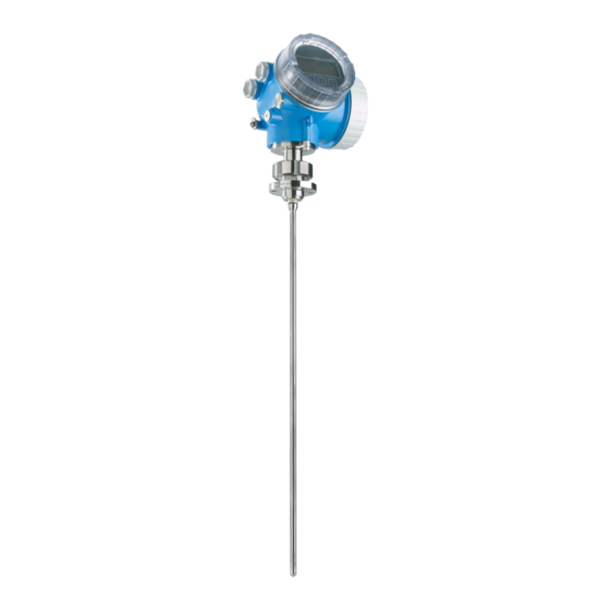
Levelflex FMP53 Product description Product description Compact device Levelflex A0013421 å 1 Design of the Levelflex Electronics housing Process connection Rod probe Endress+Hauser... -
Page 8: Electronics Housing
Product description Levelflex FMP53 Electronics housing A0012422 å 2 Design of the electronics housing Electronics compartment cover Display module Main electronics module Cable glands (1 or 2, depending on instrument version) Nameplate I/O electronics module Terminals (pluggable spring terminals) Connection compartment cover... -
Page 9: Incoming Acceptance And Product Identification
Levelflex FMP53 Incoming acceptance and product identification Incoming acceptance and product identification Incoming acceptance DELIVERY NOTE 1 = 2 A0013696 A0016870 A0013921 A0013922 A0013696 Endress+Hauser... -
Page 10: Product Identification
A0013696 A0014038 A0013696 A0014037 If one of the conditions does not comply, contact your Endress+Hauser distributor. Product identification The following options are available for identification of the measuring device: • Nameplate specifications • Order code with breakdown of the device features on the delivery note •... -
Page 11: Storage, Transport
Levelflex FMP53 Storage, Transport Order code: Ser. no.: Ext. ord. cd.: A0014103 å 3 Example of a nameplate Order code Serial number (Ser. no.) Extended order code (Ext. ord. cd.) Only 33 digits of the extended order code can be indicated on the nameplate. If the extended order code exceeds 33 digits, the rest will not be shown. - Page 12 Storage, Transport Levelflex FMP53 A0014267 Endress+Hauser...
-
Page 13: Mounting
Levelflex FMP53 Mounting Mounting Suitable mounting position A0014130 6.1.1 Mounting distances • Distance (A) between wall and rod probe: – for smooth metallic walls: > 50 mm (2") – for plastic walls: > 300 mm (12") mm to metallic parts outside the vessel •... -
Page 14: Special Mounting Conditions
Mounting Levelflex FMP53 When mounting the electronics housing into a recess (e.g. in a concrete ceiling), observe a minimum distance of 100 mm (4 inch) between the cover of the terminal compartment / electronics compartment and the wall. Otherwise the connection compartment / electronics compartment is not accessible after installation. - Page 15 Levelflex FMP53 Mounting 6.2.2 Plastic or glass tanks: Mounting the probe externally at the wall A0014150 Plastic or glass tank Metall sheet with threaded sleeve No free space between tank wall and probe! Requirements • The dielectric constant of the medium must be at least DC > 7.
-
Page 16: Mounting The Device
Mounting Levelflex FMP53 Compensation with the gas phase compensation factor The effect of the dielectric wall can be compared to the effect of a dielectric gas phase. Thus it can be compensated for in the same manner. The compensation factor if given by the quotient of the actual probe length LN and the probe length meausred when the tank is empty. - Page 17 Levelflex FMP53 Mounting 6.3.2 Preparing the device for mounting When shortening the probe: Enter the new length of probe into the Quick Setup which can be found in the electronics housing behind the display module. A0014241 Shortening rod probes Rod probes must be shortened if the distance to the container floor or outlet cone is less than 10 mm (0.4 in).
-
Page 18: Post-Installation Check
Mounting Levelflex FMP53 3. Firmly tighten the securing screw. (1,5 Nm for plastics housing; 2,5 Nm for aluminium or stainless steel housing). 6.3.4 Turning the display module 3 mm A0013905 1. Loosen the screw of the securing clamp of the electronics compartment cover using an Allen key and turn the clamp 90°... -
Page 19: Electrical Connection
Levelflex FMP53 Electrical connection Electrical connection Connection options 7.1.1 FOUNDATION Fieldbus A0011341 å 4 Terminal assignment FOUNDATION Fieldbus Terminals FOUNDATION Fieldbus Cable screen: Observe cable specifications (® ä 21) Cable entry Potential equalization Endress+Hauser... - Page 20 Electrical connection Levelflex FMP53 7.1.2 Switch output A0013759 Terminals switching output (Open collector) Connection cable switching output Cable entry Switching output Function Open collector switching output Switching behavior Binary (conductive or non-conductive), switches when the programmable switch point is reached...
-
Page 21: Connection Conditions
Connection conditions 7.2.1 Cable specification FOUNDATION Fieldbus • Endress+Hauser recommends using twisted, shielded two-wire cables. • Terminals for wire cross-sections: 0.5 to 2.5 mm (20 to 14 AWG) • Cable outer diameter: 5 to 9 mm (0.2 to 0.35 in) For further information on the cable specifications, see Operating Instructions BA00013S "FOUNDATION Fieldbus Overview", FOUNDATION Fieldbus Guideline and IEC... -
Page 22: Connection Data
• Integrated overvoltage protection (in preparation) Product structure: Feature 610 "Accessory mounted", option NA "Overvoltage protection". • External overvoltage protection, e.g. Endress+Hauser's HAW562 or HAW569. For detailed information please refer to the following documents: • HAW562: TI01012K • HAW569: TI01013K Connection data 7.3.1... - Page 23 Levelflex FMP53 Electrical connection A0012619 1. Loosen the screw of the securing clamp of the connection compartment cover and turn the clamp 90° counterclockwise. 2. Unscrew the connection compartment cover. 3. Push the cable through the cable entry. To ensure tight sealing, do not remove the sealing ring from the cable entry.
-
Page 24: Post-Connection Check
Electrical connection Levelflex FMP53 9. Screw the cover onto the connection compartment. 10. For instruments with safety pin for the lid: Adjust the safety pin so that its edge is over the edge of the display lid. Tighten the safety pin. -
Page 25: Integration Into A Foundation Fieldbus Network
Levelflex FMP53 Integration into a FOUNDATION Fieldbus network Integration into a FOUNDATION Fieldbus network Device Description (DD) You require the following to configure a device and integrate it into an FF network: • An FF configuration program • The Cff file (Common File Format: *.cff) •... - Page 26 Integration into a FOUNDATION Fieldbus network Levelflex FMP53 – EH_Levelflex_xxxxxxxxxx – RESOURCE_xxxxxxxxxxx (RB2) SETUP_ xxxxxxxxxxx (TRDSUP) ADV_SETUP_ xxxxxxxxxxx (TRDASUP) DISPLAY_ xxxxxxxxxxx (TRDDISP) DIAGNOSTIC_ xxxxxxxxxxx (TRDDIAG) EXPERT_CONFIG_ xxxxxxxxxxx (TRDEXP) EXPERT_INFO_ xxxxxxxxxxx (TRDEXPIN) SERVICE_SENSOR_ xxxxxxxxxxx (TRDSRVSB) SERVICE_INFO_ xxxxxxxxxxx (TRDSRVIF) DATA_TRANSFER_ xxxxxxxxxxx (TRDHROM)
-
Page 27: Block Model
Endress+Hauser Guideline BA00062S. The guideline provides an overview of the standard function blocks that are described in FOUNDATION Fieldbus Specifications FF 890 - 894. It is designed to help operators use the blocks implemented in the Endress+Hauser field devices. Endress+Hauser... -
Page 28: Assignment Of The Measured Values (Channel) In An Ai Block
Integration into a FOUNDATION Fieldbus network Levelflex FMP53 8.4.2 Block configuration when device is delivered Device_01 4841.000 DIAGNOSTIC RESOURCE DISPLAY DATA_TRANSFER SETUP ANALOG_INPUT_1 ADV_SETUP ANALOG_INPUT_2 EXPERT_CONFIG EXPERT_INFO SERVICE_SENSOR SERVICE_INFO ARITHMETIC SIGNAL_CHAR INPUT_SELECTOR INTEGRATOR ANALOG_ALARM A0017217 å 8 Block configuration when device is delivered... -
Page 29: Methods
Levelflex FMP53 Integration into a FOUNDATION Fieldbus network Channel Measured value 32785 Absolute EOP amplitude 32786 Absolute echo amplitude 32787 Absolute interface amplitude 32856 Distance 32885 Elektronic temperature 32938 Interface linearized 32949 Level linearized 33044 Relative echo amplitude 33045 Relative interface amplitude... -
Page 30: Commissioning Via Operating Menu (On-Site Display, Fieldcare)
Commissioning via operating menu (On-site display, FieldCare) Levelflex FMP53 Commissioning via operating menu (On-site display, FieldCare) Display and operating module 9.1.1 Display appearance User ABC_ DEFG HIJK LMNO PQRS TUVW A0012635 å 9 Appearance of the display and operation module for on-site operation Measured value display (1 value max. - Page 31 Levelflex FMP53 Commissioning via operating menu (On-site display, FieldCare) 9.1.2 Navigation and selection from a list Use the operating keys to navigate within the operating menu and to select options from a list. Meaning "Minus" key Henceforth represented by S.
-
Page 32: Operating Concept
Commissioning via operating menu (On-site display, FieldCare) Levelflex FMP53 Operating concept 9.2.1 Structure Language Display/operation Parameter 1 Parameter 2 Parameter N Setup Setup parameter 1 Setup parameter 2 Setup parameter N Enter access code Advanced setup Parameter 1 Parameter N... - Page 33 Levelflex FMP53 Commissioning via operating menu (On-site display, FieldCare) 9.2.2 Submenus and user roles The submenus are designed for different user roles. A user role is defined by typical tasks within the lifecycle of the device. User role Typical tasks...
-
Page 34: Adjust The Display Contrast
Commissioning via operating menu (On-site display, FieldCare) Levelflex FMP53 Adjust the display contrast • O + F (pressed simultaneously): increases the contrast. • S + F (pressed simultaneously): decreases the contrast. Unlock the device If the device has been locked, it must be unlocked before the measurement can be configured. - Page 35 Levelflex FMP53 Commissioning via operating menu (On-site display, FieldCare) 1. Unscrew the lid from the compartment for the display and operating module. 2. Slightly turn the display and operating module to remove it from the compartment. 3. Set the locking switch (WP: Write Protection) into the desired position. (A): unlocked; (B): locked.
-
Page 36: Set The Operating Language
Commissioning via operating menu (On-site display, FieldCare) Levelflex FMP53 Set the operating language A0013637 Endress+Hauser... -
Page 37: Configuration Of A Level Measurement
Levelflex FMP53 Commissioning via operating menu (On-site display, FieldCare) Configuration of a level measurement 20 mA 100% 4 mA A0011360 å 13 Configuration parameters for level measurements in liquids LN = Length of probe R = Reference point of the measurement... -
Page 38: User-Specific Applications (Operation)
Commissioning with a FOUNDATION Fieldbus configuration program (block-oriented operation) Levelflex FMP53 Step Parameter Action Setup ® Signal quality Displays the signal quality of the level echo. Setup ® Mapping ® Confirm Compare the displayed distance to the real distance in order to start the distance recording of the mapping curve. - Page 39 Levelflex FMP53 Commissioning with a FOUNDATION Fieldbus configuration program (block-oriented operation) 1. If necessary, change the block name. 2. Set the block mode to OOS by means of the Block Mode/MODE_BLK parameter, TARGET element. 3. Configure the device in accordance with the measuring task (® ä 42) .
-
Page 40: Scaling Of The Measured Value In An Ai Block
Commissioning with a FOUNDATION Fieldbus configuration program (block-oriented operation) Levelflex FMP53 parameters. Reporting to the field host system only takes place with alarms with a priority greater than 2. 8. Set the block mode to Auto using the Block Mode/MODE_BLK parameter, TARGET element. -
Page 41: Language Selection
Levelflex FMP53 Commissioning with a FOUNDATION Fieldbus configuration program (block-oriented operation) 10.3 Language selection Step Block Parameter Action DISPLAY (TRDDISP) Language (language) Select language Selection: • 32805: Arabian • 32824: Chinese simplified • 32842: Czech • 32881: Dutch • 32888: English •... -
Page 42: Configuration Of A Level Measurement
Commissioning with a FOUNDATION Fieldbus configuration program (block-oriented operation) Levelflex FMP53 10.4 Configuration of a level measurement The Setup method can also be used to configure the measurement. It is called up via the SETUP (TRDSUP) transducer block. 20 mA... - Page 43 • 33100: Tank empty only available for coated probes and "Tank type" = "Bypass/pipe" If required, lower DCs can ben entered into the "DC value (dc_value)" parameter. However, for DC<1.6 the measuring range may be reduced; for details please contact Endress+Hauser. Endress+Hauser...
-
Page 44: Configuration Of The On-Site Display
Commissioning with a FOUNDATION Fieldbus configuration program (block-oriented operation) Levelflex FMP53 10.5 Configuration of the on-site display 10.5.1 Factory settings of the on-site display for level measurements Parameter Factory setting for devices with 1 current Factory setting for devices with 2 current... -
Page 45: Protection Of The Settings Against Unauthorized Changes
Levelflex FMP53 Commissioning with a FOUNDATION Fieldbus configuration program (block-oriented operation) While this action is in progress, the configuration cannot be edited via the local display and a message on the processing status appears on the display. For devices with FOUNDATION Fieldbus communication, the PD Tag parameter is also transmitted when duplicating the parameter configuration. - Page 48 *71163452* KA01108F/00/EN/01.12 71163452 71163452 CCS/COSIMA...