
Related Manuals for Toro Spray Master


Summary of Contents for Toro Spray Master
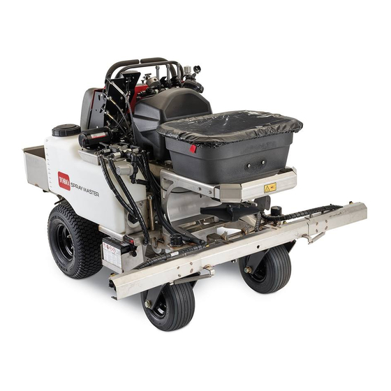
- Page 1 Form No. 3436-986 Rev A 36in Sprayer Spray Master Model No. 34231—Serial No. 400000000 and Up *3436-986* A Register at www.Toro.com. Original Instructions (EN)
- Page 2 Section 4442 or 4443 to use or operate the engine on additional information, contact an Authorized Service any forest-covered, brush-covered, or grass-covered Dealer or Toro Customer Service and have the model land unless the engine is equipped with a spark and serial numbers of your product ready.
-
Page 3: Table Of Contents
Contents Servicing the Battery......... 59 Removing and Installing the Battery....61 Jump-Starting the Machine....... 62 Safety ............... 4 Servicing the Fuses .......... 63 Safety-Alert Symbol..........4 Drive System Maintenance ........64 General Safety ........... 4 Checking the Tire Pressure....... 64 Safety and Instructional Decals ...... -
Page 4: Safety
General Safety This machine is capable of amputating hands and feet and of throwing objects. Toro designed and tested this machine to offer reasonably safe service; however, failure to comply with safety instructions may result in injury or death. -
Page 5: Safety And Instructional Decals
Safety and Instructional Decals • Keep all safety signs legible. Remove all grease, dirt, and debris from safety signs and instructional labels. • Replace all worn, damaged, or missing safety decal126-2055 signs. 126-2055 • When you install replacement components, ensure 1. - Page 6 decal135-6398 135-6398 1. Read the Operator’s 3. Only use blue-colored Manual. 10W-50 engine oil. 2. Only use green-colored 15W-50 hydraulic fluid. decal135-6420 135-6420 decal135-6424 135-6424...
- Page 7 decal135-6430 135-6430 1. Press and hold the foot 2. Release the foot pedal to pedal to lock the caster unlock the caster wheels wheels in the straight to allow turning. position. decal135-6725 135-6725 1. Cutting/dismemberment hazard of hand, spinner—stay away from moving parts. decal135-6728 135-6728 1.
- Page 8 decal135-7811 135-7811 1. Fast 14. Hour meter 2. Slow 15. Spreader speed 3. Neutral 16. Spreader speed—increase 4. Reverse 17. Spreader speed—decrease 5. Warning—read the Operator’s Manual; do not operate this 18. Spray pump—on machine unless you are trained; wear hearing protection. 6.
- Page 9 decal135-7911 135-7911 1. Hydro oil level—Full 2. Hydro oil level—Add 142-3313 Spreader / Sprayer Calibration: Mixing of liquid or dry product should be in accordance to manufacturers labels. Remember this is designed for low volume spraying so the mix will be more concentrated. Remember that your machine is factory set to put down 1/3 gallon of liquid per 1,000 sq.
- Page 10 decal142-3351 142-3351 1. Spread On-Pull handle up. 5. Spread Lock-Rotate counterclockwise to unlock; rotate clockwise to lock. 2. Spread Off-Push handle 6. Deflector-Pull knob up to down open 3. Spread pattern control-Pull 7. Deflector-Push knob down handle up if heavy on left to close side 4.
-
Page 11: Setup
Setup Loose Parts Use the chart below to verify that all parts have been shipped. Procedure Description Qty. – No parts required Connect the battery. Media and Additional Parts Description Qty. Operator's Manual Read before operating the machine. Start the machine. Checking the Tire Air Checking the Pressure... -
Page 12: Connecting The Battery
Connecting the Battery No Parts Required Procedure Install the negative battery cable to the negative (–) battery terminal with a carriage bolt and flanged locknut (Figure g311995 Figure 3 1. Flange locknut 3. Negative battery terminal 2. Negative battery cable 4. -
Page 13: Product Overview
Product Overview g311360 Figure 4 1. Spray wand 7. Motion-control levers 2. Fuel-tank cap 8. Control panel 3. Hopper cover 9. Platform 4. Hopper 10. Sprayer-tank cap 5. Spreader controls 11. Sprayer nozzles 6. Reference bar 12. Battery Controls Motion-Control Levers Use the motion-control levers to drive the machine Machine Controls forward, reverse, and turn either direction... -
Page 14: Engine Controls
Caster Wheel-Lock Pedal Ignition Switch • Press and hold the caster wheel-lock pedal (Figure The ignition switch is located at the left side of the 6) to lock the caster wheels in the straight position. control console (Figure • Release the caster wheel-lock pedal to unlock the Use the ignition switch to start and run, or shut off the caster wheels, and allow the machine to freely engine. -
Page 15: Sprayer Controls
Sprayer Controls Deflector Control The deflector control (Figure 8) pivots the deflector into the spreader pattern. Diffuser Control The diffuser control (Figure 8) shifts the product placement of the impeller either to the edge of the impeller or to the middle of the impeller. Drop-rate Cam and Linkage The drop-rate cam and linkage are located at the front of the machine and below the hopper on the spreader... -
Page 16: Specifications
Specifications Overall width left and right booms 161.2 cm (63-1/2 extended inches) left and right booms 91.4 cm (36 folded inches) Overall length 179.4 cm (70-5/8 inches) Overall height 128.2 cm (50-1/2 inches) Weight sprayer tank and 376 kg (829 lb) g311618 hopper empty Figure 11... -
Page 17: Before Operation
If you are using more than 1 chemical, read the safely perform the job. Use only accessories and information about each chemical. Refuse to attachments approved by Toro. operate or work on the spreader-sprayer if this • Inspect the area where you will use the equipment, information is not available. -
Page 18: Performing Daily Maintenance
Fuel Safety • Gasoline is harmful or fatal if swallowed. Long-term exposure to vapors has caused cancer Use extreme care when handling fuel. in laboratory animals. Failure to use caution may cause serious injury or illness. In certain conditions gasoline is extremely flammable and its vapors are explosive. -
Page 19: Fuel Specification
14). Important: If the engine runs with the lanyard removed from the presence-control switch, shut off the engine with the key and contact your authorized Toro dealer. Rotate the ignition switch to the position. Fuel Specification Petroleum Use unleaded gasoline with an octane rating of 87 fuel or higher ((R+M)/2 rating method). -
Page 20: During Operation
During Operation overturn the machine or cause you to lose your balance or footing. – Do not operate the machine with damaged During Operation Safety guards, shields, or covers. Always have safety shields, guards, switches and other devices in place and working properly. General Safety –... - Page 21 – Keep children out of the working area and – Do not use the spray wand if the trigger lock is under the watchful care of another responsible damaged or missing. adult. – Do not keep the spray wand in the locked-open –...
-
Page 22: Operating The Machine
Operating the Machine Starting the Engine CAUTION The machine produces sound levels in excess of 85 dBA at the operator’s ear, and may cause hearing loss through extended periods of exposure. Wear hearing protection while operating the machine. Move the motion-control levers to the N EUTRAL position and engage the parking brake;... - Page 23 Remove the key; refer to Ignition Switch (page 14). Remove the lanyard clip from yourself. Driving the Machine CAUTION The machine can turn rapidly by moving the steering control to the far right or left. You may lose control of the machine, which may injure you and others, and damage the machine.
-
Page 24: Operating The Spreader
The Display Stopping the Machine Refer to the User’s Manual for the display of the CAUTION following information: Children or bystanders may be injured if they Display Information Types move or attempt to operate the machine while it is unattended. •... - Page 25 Hopper Controls apply the granular materials to the work site, and finish by cleaning the spreader. Important: When you use your spreader, thoroughly clean it at the end of the day. Adjusting the Impeller-Speed Control g312313 Figure 19 g311592 1. Unlock 4.
- Page 26 • Pull the handle to broadcast granular product graduated measuring cylinders. In the example below, from the left side of the impeller. the 15 shallow collection pans approximately 30 cm (12 inches) wide, 91 cm (36 inches) long, and 5 cm •...
- Page 27 Determining the Distribution Pattern Set the diffuser control to the middle of its travel and lock it; refer to Adjusting the Diffuser Control (page 26). Adjust the impeller speed control to set the broadcast pattern width; refer to Adjusting the Impeller-Speed Control (page 25).
- Page 28 Note: amount of the material that you observed in the In this example we added 11.3 kg (25 center graduated cylinder. lb) of material. Go to the two corresponding pans. Starting from Drive the spreader over the calibration course the outer edge, measure the distance between while applying the material.
- Page 29 Filling the Spreader Hopper Maximum hopper weight capacity: 54 kg (120 lb) Drive the machine to the work site. Move the machine to a level surface, move motion-control lever to the N position, EUTRAL shut off the engine, wait for all moving parts to stop, remove key, and engage parking brake.
- Page 30 Using the Spreader Spreading Charts Note: The cam setting tables for granular material and the grass seed are provided with permission from the Brinly-Hardy Company; reference the Brinly-Hardy Company website for more information. Use these charts as an approximate guideline only. Other factors, such as weather conditions, spreader operation, and the condition of material affects spreader performance.
- Page 31 Cam Settings for Grass Seed Application (cont'd.) Type Bag Weight Coverage - m Cam Setting – Cam Setting – Spreader Width Full Rate Half Rate Mixtures Including 0.9 kg (2 lb) 93 (1,000) Coarse Seeds 1.81 kg (4 lb) 93 (1,000) 2.72 kg (6 lb) 93 (1,000) Rye Grasses or Tall...
- Page 32 • If the material is broadcast too heavy at the left side of the machine, push the diffuser control down slightly; refer to 3 of Figure • If the material is broadcast too heavy at the right side of the machine, pull the diffuser control up slightly;...
-
Page 33: Operating The Sprayer
Operating the Sprayer CAUTION Chemicals are hazardous and can cause personal injury. • Read the chemical manufacturer’s directions on the label before handling the chemicals; follow all manufacturer recommendations and precautions. • Keep chemicals away from your skin. Should contact occur, wash the affected area thoroughly with soap and clean water. - Page 34 Extending and Folding the Outer Selecting the Right Spray Tank Spray Booms Rotate the valve handles as shown in Figure g311514 Figure 32 3. Right tank suction valve 1. Left tank return valve position) position) g312788 CLOSE OPEN Figure 30 2.
- Page 35 Transferring Fluid Between Tanks Transferring Fluid from the Left Tank to the Right Tank Ensure that the right tank has capacity to hold fluid from the left tank. Ensure that the handles for the spray-control valves are in the position (Figure 34).
- Page 36 Note: Each sprayer tip shuts off when sprayer pressure is <0.3 bar (5 psi) to prevent dripping. Nozzle Application Rate Table Nozzle Ground speed Sprayer Application tip color pressure rate Yellow 8 kph 5 mph 40 psi 0.27 1.0 L/ 93 m (1/4) gallon/...
- Page 37 Calculating the Amount of Product for a Solution of Chemical Multiply the average product application rate by the 1-gallon nozzle tip factor to determine the 1-gallon application rate. Example: median application rate value—38 ml/93 m (1.3 fl oz per 1,000 ft ) of 1.1 to 1.5) x 3 (lavender nozzle tip—nozzle tip factor) = 3.9 (adjusted application rate)
- Page 38 Using the Sprayer Add 3/4 of the required water to the sprayer tank through the filler neck. Before Operating the Sprayer Important: Always use fresh, clean water in the spray tank. Do not pour chemical Some chemicals are more aggressive than others concentrate into an empty tank.
- Page 39 Note: • Calibrate the sprayer before you start the Watch for plugged sprayer nozzles. spray application; refer to Sprayer Nozzle Application • Move the boom sprayer-control valves to the O Rate (page 36). position to stop the spray flow before stopping the motion of the machine.
-
Page 40: After Operation
Ensure that the 3 boom sprayer-control valves When finished spraying, if you locked the trigger are in the O position. of the spray-wand—unlock it, and release the trigger (Figure Remove the spray wand from the tool clip at the left side of the machine (Figure 45). -
Page 41: Cleaning And Lubricating The Spreader
Cleaning and Lubricating the Spreader Cleaning the Spreader Service Interval: After each use Important: Do not use brackish or reclaimed water to clean the machine. Drive the machine to a designated cleaning area with a level surface. g312831 Move the motion-control levers to the N EUTRAL Figure 48 position, shut off the engine, wait for all moving... -
Page 42: Cleaning The Sprayer
Lubricating the Spreader Fill the sprayer tank with 19 L (5 US gallons) or more of clean water and install the cap; refer to Apply water-displacing lubricant to the control Filling the Tank (page 38). cables and pivot points as shown in Figure Engage the parking brake, move the motion-control levers to the N... - Page 43 Cleaning the External Components Rotate the strainer bowl counterclockwise and remove the bowl and screen from the body of Using a hose to wash off the outside of the the strainer (Figure 52). sprayer tank with clean water. Note: Remove the strainer bowl by hand. Note: Do not use a power washer to clean the machine.
- Page 44 Cleaning the Sprayer Nozzles Service Interval: After each use Rotate the nozzle cap 90° counterclockwise and remove the cap from the nozzle body (Figure 53). g311414 Figure 53 1. Nozzle body 3. Sprayer tip 4. Nozzle cap 2. Strainer g311417 Figure 54 Remove the sprayer tip and strainer from the nozzle body...
-
Page 45: Transporting The Machine
Transporting the Machine If using a trailer, connect it to the towing vehicle and connect the safety chains. Machine weight: 376 kg (829 lb)—both sprayer tank If applicable, connect the trailer brakes. and hopper empty; 521 kg (1150 lb)—both sprayer Lower the ramp. - Page 46 Block the tires. Use the tie-down points on the machine to securely bind the machine to the trailer or truck with straps, chains, cable, or ropes (Figure 56 Figure 57). Refer to local regulations for trailer and tie-down requirements. g313453 Figure 56 1.
-
Page 47: Maintenance
Maintenance Maintenance Safety could be dangerous. The mechanical or hydraulic jacks may not be enough support or may • While performing maintenance on the machine, malfunction, allowing the machine to fall and cause someone could start the engine. Accidental possible injury. Do not rely solely on mechanical starting of the engine could seriously injure you or or hydraulic jacks for support. -
Page 48: Recommended Maintenance Schedule(S)
Recommended Maintenance Schedule(s) Maintenance Service Maintenance Procedure Interval • Change the engine oil. After the first 5 hours • Change the hydraulic fluid and filter. After the first 100 hours • Check the safety-interlock system. • Check the engine-oil level. Before each use or daily •... -
Page 49: Notation For Areas Of Concern
Notation for Areas of Concern Inspection performed by: Item Date Information Important: Refer to your engine owner’s manual for additional maintenance procedures. Pre-Maintenance Procedures Preparing the Machine WARNING While you are maintaining or adjusting the machine, someone could start the engine. g311995 Accidentally starting the engine could Figure 58... - Page 50 Accessing the Engine Opening the Tanks At the spray tank that you need to move, remove the flange-head bolt and flange locknut that secures the tank lock plate to the support (Figure 61). g311625 Figure 59 g311931 Figure 61 Installing the Knee Pad Left shown, the right tank is similar.
-
Page 51: Lubrication
Lubrication Closing the Tanks Rotate the tank closed as shown in Figure Grease Specification Grease type: National Lubricating Grease Institute (NGLI) grade No. 2 multi-purpose gun grease. Greasing the Caster Pivots Service Interval: Every 80 hours/Every 2 weeks (whichever comes first) Prepare the machine for maintenance;... -
Page 52: Lubricating The Caster-Axle Bearings
Lubricating the Caster-Axle Greasing the Belt Tensioner Bearings Service Interval: Monthly Prepare the machine for maintenance; refer to Service Interval: Yearly Preparing the Machine (page 49). Prepare the machine for maintenance; refer to At the bottom of the machine, wipe the grease Preparing the Machine (page 49). -
Page 53: Engine Maintenance
Engine Oil Specification Close the spray tanks; refer to Closing the Tanks (page 51). Oil Type: Toro 4-Cycle Premium Engine Oil or a high-quality detergent oil (including synthetic) API Replacing the Air-Cleaner service SJ or higher Assembly Oil viscosity: Refer to the table below. -
Page 54: Checking The Engine-Oil Level
Checking the Engine-Oil Level Service Interval: Before each use or daily Important: Do not operate the engine with the oil level below the Low (or Add) mark on the dipstick, or over the Full mark. Move the machine to a level surface. Prepare the machine for maintenance;... -
Page 55: Changing The Oil Filter And Engine Oil
Changing the Oil Filter and Engine Oil Service Interval: After the first 5 hours Every 100 hours (more often under severe condition). Draining the Engine Oil g312969 Prepare the machine for maintenance; refer to Figure 74 Preparing the Machine (page 49). -
Page 56: Servicing The Spark Plug
g312874 Figure 76 1. Dipstick and filler neck g312872 Figure 78 1. Maximum oil level 3. Filler neck Slowly pour 1.6 L (56 fl oz) of the specified oil (dipstick) into the filler neck (Figure 77) of the engine; 2. Minimum oil level (dipstick) refer to Engine Oil Specification (page 53). - Page 57 g206628 Figure 80 Installing the Spark Plug Tighten the spark plug as follows: • New spark plug—12 to 15 N∙m (8.7 to 10.8 ft-lb) • In-service spark plug—23 to 27 N∙m (16.6 to 19.5 ft-lb) g312978 g313515 Figure 81 Close and secure the left and right spray tanks; g027478 refer to Closing the Tanks (page...
-
Page 58: Fuel System Maintenance
Fuel System Secure the fuel hoses to the filter with the clamps (Figure 82). Maintenance Close and secure the right spray tank; refer to Closing the Tanks (page 51). Replacing the Fuel Filter Service Interval: Every 400 hours Rotate open the right spray tank; refer to Opening the Tanks (page 50). -
Page 59: Electrical System Maintenance
Checking the Battery Charge Electrical System Maintenance CAUTION If the ignition is in the O position, there is potential for sparks and for engine Servicing the Battery components to move. Sparks could cause an explosion or moving parts could accidentally Service Interval: Monthly engage, causing personal injury. - Page 60 Charging the Battery Battery Charge Table Voltage Percent Maximum Charging WARNING Reading Charge Charger Interval Settings Charging the battery produces gasses that 12.6 or 100% 16 V/ No Charging can explode. greater Required Never smoke near the battery and keep sparks 12.4 to 12.6 30 Minutes 75 to 100%...
-
Page 61: Removing And Installing The Battery
Removing and Installing the Battery Removing the Battery WARNING Battery terminals or metal tools could short against metal machine components, causing sparks. Sparks can cause the battery gasses to explode, resulting in personal injury. • When removing or installing the battery, do not allow the battery terminals to touch g313031 any metal parts of the machine. -
Page 62: Jump-Starting The Machine
Jump-Starting the Machine Note: The positive battery cable is wired to the starter or solenoid. DANGER Jump-starting a battery that is cracked, frozen, has low electrolyte level, or an open/shorted battery cell can cause an explosion, resulting in serious personal injury. Do not jump-start a battery if these conditions exist;... -
Page 63: Servicing The Fuses
Servicing the Fuses Close the cover onto the fuse holder until the cover latches securely (Figure 87). The electrical system is protected by fuses. If a fuse Close and secure the right spray tank; refer to opens, check the component or circuit for a load or Closing the Tanks (page 51). -
Page 64: Drive System Maintenance
Brake Maintenance Drive System Maintenance Adjusting the Parking Checking the Tire Pressure Brake Service Interval: Every 40 hours Prepare the machine for maintenance; refer to Preparing the Machine (page 49). Tire air pressure specification: 124 kPa (18 psi) Check the air pressure in the drive tires; refer to Important: Do not exceed the maximum air Checking the Tire Pressure (page... -
Page 65: Belt Maintenance
Belt Maintenance Checking the Belt for Wear Service Interval: Every 80 hours/Every 2 weeks (whichever comes first) Prepare the machine for maintenance; refer to Preparing the Machine (page 49). Raise the machine and support it with jack stands. Check the belt for wear of damage. g313243 Figure 92 Note:... -
Page 66: Controls System Maintenance
Controls System Maintenance Adjusting the Maximum Forward Speed Prepare the machine for maintenance; refer to Preparing the Machine (page 49). Loosen the 2 knobs that secure the speed bar (Figure 95). g313254 Figure 94 g313377 Figure 95 1. Knobs 3. Increase the maximum forward speed 4. -
Page 67: Adjusting The Motion-Control Linkage
Tighten the 2 knobs that secure the speed bar (Figure 95). Adjusting the Motion-Control Linkage Prepare the machine for maintenance; refer to Preparing the Machine (page 49). Loosen the 2 knobs that secure the speed bar, and push the speed bar forward (Figure 96). -
Page 68: Adjusting The Motion Control Tracking
Loosen the 2 jam nuts that secure the motion-control rod at the upper and lower ball joints (Figure 99). g313362 Figure 98 1. Left motion-control rod 4. Jam nut 2. Right motion-control rod 5. Jam nut (rod adjustment) g313362 Figure 99 3. -
Page 69: Hydraulic System Maintenance
100); refer to Hydraulic Fluid Specification Specification (page 69). Install the cap (Figure 100). Preferred fluid: Toro Hypr-Oil 500 Install the knee pad; refer to Installing the Knee Optional fluid: 15W-50 API rating CI-4/CF hydraulic Pad (page 50). fluid Checking the Hydraulic... -
Page 70: Purging Air From The Hydraulic System
g313257 Figure 102 g313237 1. Hydraulic filter 2. Filter head Remove the filter, and allow the hydraulic fluid to drain (Figure 102). Apply a thin coat of the specified hydraulic fluid to the gasket of the new hydraulic filter; refer to Hydraulic Fluid Specification (page 69). -
Page 71: Maintaining The Chassis
Maintaining the Chassis Maintaining the Sprayer System Checking the Machine for Loose Hardware Checking Sprayer System Service Interval: Before each use or daily Service Interval: Every 50 hours Prepare the machine for maintenance; refer to Prepare the machine for maintenance; refer to Preparing the Machine (page 49). -
Page 72: Cleaning
Cleaning Cleaning the Engine and the Exhaust System Area Service Interval: After each use (clean more often when operating the machine in dry or dirty conditions.) CAUTION Excessive debris around engine-air intake and exhaust system area can cause engine, exhaust area, and hydraulic system to g313101 overheat which can create a fire hazard. -
Page 73: Storage
Storage Federal law states that batteries should not be placed in the garbage. Management and disposal practices for batteries must follow relevant federal, state, or Set sprayer-pump switch to the O position, local laws. stop the machine, move motion-control lever to Take the battery to a local certified-recycling center the N position, shut off the engine, wait... - Page 74 Start the machine and set sprayer-pump switch to the O position Move the 3 boom spray-control valves to the O position. Note: Run the sprayer pump until the spray nozzles is spray air. Shut off the sprayer pump and the engine. Preparing the Sprayer System Antifreeze type: 15 L (4 US gallon) rust inhibiting, non-alcohol based, RV-antifreeze concentrate...
-
Page 75: Troubleshooting
Troubleshooting Important: Ensure that the operator safety mechanisms for the machine are connected and in proper operating condition before you use the machine. When a problem occurs, do not overlook the simple causes. For example, starting problems could be caused by an empty fuel tank. - Page 76 Testing Alternator Output CAUTION Attach meter test leads to the AC output terminals (the yellow wires) in the connector before starting the engine. If the stator is grounded (damaged or worn) and the meter test leads contact the center DC output pin (the red wire) in the connector, arcing could occur, damaging the wiring.
- Page 77 Testing the DC Output Charging Wire Use this test to check the DC output charging wire circuit. If a wiring problem exists, you can correct it before testing regulator/rectifier. Leave stator wire harness disconnected from regulator-rectifier. Ignition switch must be in OFF position. Turn the ignition switch to the position.
- Page 78 4. A fuse is open. 4. Replace the open fuse. 5. A relay or switch is worn or damaged. 5. Contact an authorized Toro service dealer. The engine does not start, it starts hard, or 1. The fuel tank is empty.
- Page 79 Problem Possible Cause Corrective Action The engine overheats. 1. The engine load is excessive. 1. Reduce the ground speed of the machine. 2. The oil level in the engine is low. 2. Add oil into the engine to the proper oil level.
- Page 80 Problem Possible Cause Corrective Action No material dispensed from hopper. 1. Hopper screen is plugged. 1. Clean the hopper screen. 2. Hopper door not adjusted properly. 2. Adjust the hopper door; refer to the Adjusting the Hopper-Door Control procedure. The spray wand does not work. 1.
-
Page 81: Schematics
Schematics g271692 Electrical Schematic 135-6146 (Rev. A) - Page 82 Notes:...
- Page 83 Notes:...